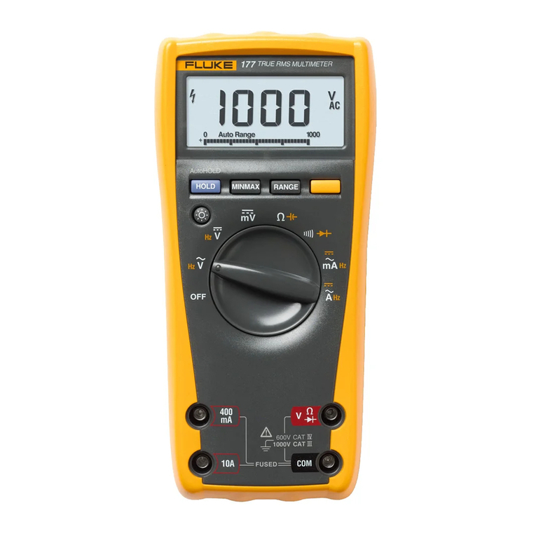
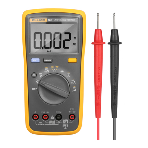
TTI 1604 User manual

THURLBY THANDAR INSTRUMENTS
40,000 COUNT DIGITAL MULTIMETER
1604
INSTRUCTION MANUAL

Table of Contents
Introduction 2
Specifications 3
Safety 7
EMC 8
Installation 9
General Operation 10
Making Measurements 12
Further Functions 14
Maintenance & Calibration 15
Remote Operation 15
Instructions en Francais 16
Bedienungsanleitung auf Deutsch 25
Istruzioni in Italiano 34
Instrucciones en Español 43
1

Introduction
This true RMS multimeter is a low-cost manual/autoranging bench-top instrument with a large,
bright LED display. It offers 4¾ digit (40,000 count) scale length and a resolution of 10µV and
10mΩ.
The key features are:
• 0.56” (14mm) high brightness LED display.
• 0.08% basic accuracy, 40,000 counts.
• Manual or autoranging.
• DC and AC Volts, DC and AC current, Resistance and Frequency measurement; Continuity
and Diode checks.
• True RMS AC measurement, 4,000 counts.
• Display nulling.
• Touch hold mode - holds onto a stable reading until updated.
• Remote control and data-logging to disk using optional Windows software.
• Fully compliant with EN61010-1 Safety and EN61326 EMC standards.
TEST EQUIPMENT RISK ASSESSMENT
Recommendation from the U.K. Health and Safety Executive
Users of this equipment and or their employers are reminded that Health and
Safety Legislation require them to carry out valid risk assessments of all electrical
work so as to identify potential sources of electrical danger and risk of electrical
injury such as from inadvertent short circuits. Where the assessments show that
the risk is significant then the use of fused test leads constructed in accordance
with the HSE guidance note GS38 ‘Electrical Test Equipment’ for use by
electricians’ should be used.
2

Specifications
ACCURACY
Accuracies apply for 1 year 19°C to 25°C. Temperature coefficient outside these limits is
<0.1 x quoted range accuracy per °C.
DC Volts
Range Accuracy Resolution Notes
400mV 0.08% ± 4 dig. 10µV 265V DC/AC rms max Input impedance 10MΩ nominal
4V 0.08% ± 4 dig. 100µV Max in
p
ut 1000V NMR:>60dB @ 50/60Hz †
40V 0.08% ± 4 dig. 1mV DC/AC pk. CMR:>90dB @ DC/50Hz/60Hz†
400V 0.08% ± 4 dig. 10mV
1000V 0.09% ± 4 dig. 100mV
AC Volts (True RMS)
Range Accuracy Resolution
45Hz - 400Hz 400Hz - 4kHz 4kHz - 20kHz
400mV 1% ± 4 dig. 2% ± 4 dig. 100µV
4V 1mV
40V 0.5% ± 4 dig 2% ± 4 dig 5% ± 4 dig. 10mV
400V - - 100mV
750V 1% ± 4 dig. - - 1V
Accuracies apply for readings between 400 and 4,000 counts. Additional error at crest
factor = 3 is typically 1%. Input impedance = 10MΩnominal.
1kΩunbalanced CMR = >60dB at DC/50Hz/60Hz†.
Max. input = 750V rms, 1kV pk. (265Vrms on 400mV range).
Resistance
Range Accuracy Resolution Notes
400Ω0.15% ± 6 dig.∗10mΩ
4kΩ0.1% ± 4 dig. 100mΩ
40kΩ0.1% ± 4 dig. 1ΩMax. input 265V DC or ACrms any range.
400kΩ0.15% ± 4 dig. 10ΩMax. open circuit voltage 4V.
4MΩ0.3% ± 6 dig. 100Ω
40MΩ (up to 20MΩ) 1.0% ± 10 dig. 1kΩ
40MΩ (up to 40MΩ) 2.0% ± 10 dig 1kΩ
∗ after Null
† 60Hz rejection is a factory option.
3

DC Current
Range Accuracy Resolution Notes
4mA 0.1% ± 4 dig. 0.1µA Max. input 1A, 250V, fuse protected
400mA 0.1% ± 4 dig. 10µA Voltage burden <500mV
10A (up to 1A) 0.3% ± 4 dig. 1mA
10A (up to 5A) 1.0% ± 4 dig. 1mA Max. input 10A, 250V, fuse protected
10A (up to 10A) 3% ± 10 dig 1mA Voltage burden <500mV
AC Current (True RMS)
Range Accuracy (45Hz - 10kHz) Resolution Notes
4mA 0.5% ± 4 dig. 1µA Max. input 1A, 250V, fuse protected
400mA 0.5% ± 4 dig. 100µA Voltage burden <500mV
10A (up to 1A) 0.8% ± 4 dig. 10mA
10A (up to 5A) 1.5% ± 4 dig 10mA Max. input 10A, 250V, fuse protected
10A (up to 10A) 3% ± 4 dig. 10mA Voltage burden <500mV
Accuracies apply for readings between 400 and 4,000 counts. Additional error at crest factor = 3
is typically 1%.
Frequency
Range Accuracy Resolution Gate Notes
4kHz 0.01% ± 1 dig. 0.01Hz 1s Sensitivity set by
40kHz 0.01% ± 1 dig. 0.1Hz 10s AC range setting
Continuity and Diode Test
Continuity: 4kΩrange selected; audible tone sounds for impedance <10Ω.
Diode Test: Test current approximately 1mA at 1V; displays voltages up to 3V.
Maximum Open Circuit
Voltage:
4V
Maximum Input: 265V DC or AC rms.
FURTHER FUNCTIONS
Hold: Reading is frozen
T-Hold (Touch & Hold): Reading is frozen when stable.
Min/Max: Minimum and maximum readings stored.
Null (Relative): Stores current reading and subtracts it from future readings. Up to
±1,000 counts can be nulled without restricting the measurement
range. Counts greater than ±1,000 can be nulled to give a Relative
reading but the measurement range is correspondingly reduced; OFL
shows in the display when the measurement range is exceeded.
4

DISPLAY
Display Type: High brightness LED. Height 0.56” (14mm).
Scale Length: 4¾ digits (40,000 counts); AC ranges 4,000 counts.
Annunciators: For all ranges, functions and program modes.
Reading Rate: 2.5 readings/sec.
Overrange: Display shows OFL if input too great for range.
GENERAL
Power: 110V-120V or 220V-240V AC ±10%, 50/60Hz, adjustable internally;
3VA max. Installation Category II. 60Hz operation is a factory option.
RS232 Interface: Baud Rate 9600. Permits remote control and data-logging to disk using
optional Windows software.
Operating Range: +5°C to + 40°C, 20% to 80% RH.
Storage Range: −40°C to + 70°C.
Environmental: Indoor use at altitudes up to 2000m, Pollution Degree 1.
Safety: Complies with EN61010-1.
EMC: Complies with EN61326.
Size: 260(W) x 88(H) x 235(D)mm, excluding handle and feet.
Weight: 2.0kg.
5

EC Declaration of Conformity
We Thurlby Thandar Instruments Ltd
Glebe Road
Huntingdon
Cambridgeshire PE29 7DR
England
declare that the
Model 1604 Digital Multimeter
meet the intent of the EMC Directive 89/336/EEC and the Low Voltage Directive 73/23/EEC.
Compliance was demonstrated by conformance to the following specifications which have been
listed in the Official Journal of the European Communities.
EMC
Emissions: a) EN61326 (1998) Radiated, Class B
b) EN61326 (1998) Conducted, Class B
c) EN61326 (1998) Harmonics, referring to EN61000-3-2 (2000)
Immunity: EN61326 (1998) Immunity Table 1, Performance B, referring to:
a) EN61000-4-2 (1995) Electrostatic Discharge
b) EN61000-4-3 (1997) Electromagnetic Field
c) EN61000-4-11 (1994) Voltage Interrupt
d) EN61000-4-4 (1995) Fast Transient
e) EN61000-4-5 (1995) Surge
f) EN61000-4-6 (1996) Conducted RF
Safety
Multimeter: EN61010-1 (1993)
Installation Category I measurements to 1000V,
Installation Category II measurements to 600V,
Pollution Degree 1.
Probes: IEC1010-2-031 (1993)
Rated to 1000V, Installation Category III.
................................................................
CHRIS WILDING
TECHNICAL DIRECTOR
2 July 2001
6

Safety
This multimeter is a Safety Class I instrument according to IEC classification and has been
designed to meet the requirements of EN61010-1 (Safety Requirements for Electrical Equipment for
Measurement, Control and Laboratory Use). It is an Installation Category II instrument intended for
operation from a normal single phase supply.
WARNING! THIS INSTRUMENT MUST BE EARTHED
Any interruption of the mains earth conductor inside or outside the instrument will make the
instrument dangerous. Intentional interruption is prohibited. The protective action must not be
negated by the use of an extension cord without a protective conductor.
The test leads supplied with this instrument meet the requirements of IEC1010-2-031 and are rated
to 1000V Category III; use only these test leads with the meter or a set of equivalent performance.
This instrument has been tested in accordance with EN61010-1 and has been supplied in a safe
condition. This instruction manual contains some information and warnings which have to be
followed by the user to ensure safe operation and to retain the instrument in a safe condition.
This instrument has been designed for indoor use in a Pollution Degree 1 environment (no pollution,
or only dry non-conductive pollution) in the temperature range 5°C to 40°C, 20% - 80% RH (non-
condensing). It may occasionally be subjected to temperatures between +5° and −10°C without
degradation of its safety. It has been designed for Installation Category II measurement use to
600V DC/rms and Installation Category I measurement use to 1000V DC/rms. The full definitions of
Categories I and II can be found in IEC664, but the following can be taken as a guide:
Installation Category I is signal level e.g. telecommunication, electronic equipment, with smaller
transient overvoltages than Installation Category II.
Installation Category II is local domestic supply level, e.g. portable equipment and appliances. In
particular, Category II does not include distribution level supplies, e.g. three phase installations
which are classified as Installation Category III.
Use of this instrument in a manner not specified by these instructions may impair the safety
protection provided. Do not operate the instrument outside its rated supply voltages or
environmental range. In particular excessive moisture may impair safety.
When the instrument is connected to its supply or its inputs are connected to live voltages, terminals
may be live and opening the covers or removal of parts (except those to which access can be
gained by hand) is likely to expose live parts. The apparatus shall be disconnected from all voltage
sources before it is opened for any adjustment, replacement, maintenance or repair.
Any adjustment, maintenance and repair of the opened instrument under voltage shall be avoided
as far as possible and, if inevitable, shall be carried out only by a skilled person who is aware of the
hazard involved.
If the instrument is clearly defective, has been subject to mechanical damage, excessive moisture
or chemical corrosion the safety protection may be impaired and the apparatus should be withdrawn
from use and returned for checking and repair.
Make sure that only fuses with the required rated current and of the specified type are used for
replacement. The use of makeshift fuses and the short-circuiting of fuse holders is prohibited.
Do not wet the instrument when cleaning it and in particular use only a soft dry cloth to clean the
display window. The following symbols are used on the instrument and in this manual:
WARNING - risk of electric shock.
mains earth (ground)
CAUTION - refer to accompanying documentation;
incorrect operation may damage the meter.
direct current
alternating current
7

EMC
This instrument has been designed to meet the requirements of the EMC Directive 89/336/EEC.
Compliance was demonstrated by meeting the test limits of the following standards:
Emissions
EN61326 (1998) EMC product standard for Electrical Equipment for Measurement, Control and
Laboratory Use. Test limits used were:
a) Radiated: Class B
b) Conducted: Class B
c) Harmonics: EN61000-3-2 (2000) Class A; the instrument is Class A by product category.
Immunity
EN61326 (1998) EMC product standard for Electrical Equipment for Measurement, Control and
Laboratory Use.
Test methods, limits and performance achieved were:
a) EN61000-4-2 (1995) Electrostatic Discharge: 4kV air, 4kV contact, Performance B.
b) EN61000-4-3 (1997) Electromagnetic Field, 3V/m, 80% AM at 1kHz, Performance B.
c) EN61000-4-11 (1994) Voltage Interrupt, 1 cycle, 100%, Performance B.
d) EN61000-4-4 (1995) Fast Transient, 1kV peak (AC line), 0.5kV peak (DC Outputs),
Performance B.
e) EN61000-4-5 (1995) Surge, 0.5kV (line to line), 1kV (line to ground), Performance A.
f) EN61000-4-6 (1996) Conducted RF, 3V, 80% AM at 1kHz (AC line only; DC Output
connections <3m not tested), Performance A.
According to EN61326 the definitions of performance criteria are:
Performance criterion A: ‘During test normal performance within the specification limits.’
Performance criterion B: ‘During test, temporary degradation, or loss of function or
performance which is self-recovering’.
Performance criterion C: ‘During test, temporary degradation, or loss of function or
performance which requires operator intervention or system reset occurs.’
Where Performance B is stated the multimeter will continue to function but accuracy may deviate
from Specification under the test conditions. However, the possible deviations are small and
infrequent and are unlikely to be a problem in practice.
Cautions
To ensure continued compliance with the EMC directive the following precautions should be
observed:
a) only use screened cables and connectors to connect between the multimeter’s RS232
interface and other equipment.
b) after opening the case for any reason ensure that all signal and ground connections are
remade correctly before replacing the cover. Always ensure all case screws are correctly
refitted and tightened.
c) In the event of part replacement becoming necessary, only use components of an identical
type, see the service manual.
8

Installation
Mains Operating Voltage
Check that the instrument operating voltage marked on the rear panel is suitable for the local
supply. Should it be necessary to change the operating voltage, proceed as follows:
1) Disconnect the instrument from all voltage sources.
2) Remove the 4 screws from the underside and lift off the case upper.
3) Remove the 3 screws securing the pcb to the case lower and lift out the pcb with front and rear
panels attached.
4) Change the voltage settings by changing the soldered links as shown below:
5) Reassemble in the reverse order.
6) To comply with safety standard requirements the operating voltage marked on the rear panel
must be changed to clearly show the new voltage setting.
Note: The transformer primary is protected by an integral thermal fuse which remains unchanged
when the operating voltage is altered.
Mains Lead
When a three core mains lead with bare ends is provided it should be connected as follows:-
Brown - Mains Live
Blue - Mains Neutral
Green / Yellow - Mains Earth
WARNING! THIS INSTRUMENT MUST BE EARTHED WHEN OPERATED FROM AN AC LINE SUPPLY
Any interruption of the mains earth conductor inside or outside the instrument will make the
instrument dangerous. Intentional interruption is prohibited. The protective action must not be
negated by the use of an extension cord without a protective conductor.
Handle
Adjust the handle position by pulling out the ends and rotating the handle to the desired position.
There are sixteen possible positions including five facing forward which provide upward tilts for
the most convenient bench operation. The handle may be swung out of the way to the back or
front of the instrument if no tilt is required. The natural spring in the handle will lock it into position
when the handle is released.
9

General Operation
This section is a general introduction to the features and organisation of the multimeter intended
to be read before using the instrument for the first time. Detailed operation is covered in the
Making Measurements section.
Connections
Input Sockets
The input sockets are 4mm safety sockets on a 19mm pitch designed to accept 4mm safety plugs
with fixed or retractable shrouds. The sockets are all rated to 1000V (Category I)/600V (Category
II) with respect to earth ground.
The input impedance between V/Ωand COM is nominally 10MΩ. The black COM socket is
considered less positive than the red socket.
The mA/10A current sockets are low impedance; the voltage burden between mA/10A and COM
at full scale is <500mV. The black COM socket is considered less positive than the white mA/10A
sockets.
Multimeter Test Leads
The test leads supplied meet the requirements of IEC1010-2-031 and are rated to 1000V
Category III. Use only the test leads provided, or a set of similar performance, to ensure safe
operation. Alternative test leads should be rated to at least 1000V (Category I),
600V (Category II) and 10A current capability.
RS232
The RS232 interface permits remote control and data-logging to disk using optional Windows
software. The interface is fully opto-isolated from the measurement system; the host computer
provides power (via the DTR and RTS lines) to the TXD opto output and drives the RXD opto
input directly. The 9-way D-type on the meter must be connected to the 9-way D-type of the PC’s
serial port via a 9-way cable (all connections made); the PC is nulled out at the multimeter
interface as shown below:
Pin Name Description
1 DCD Linked to DTR
2 TXD Transmitted data from instrument
3 RXD Received data to instrument
4 DTR DTR from host PC must be set to +9V (logic 0)
5 GND Signal ground
6 DSR Linked to DTR
7 RTS RTS from host PC must be set to -9V (logic 1)
8 CTS Linked to RTS
9 GND Signal ground
Signal grounds are connected to instrument safety ground.
To ensure compliance with EMC legislation use only screened cable assemblies with screened
connectors when connecting to other equipment.
10

Switching On
Power Switch
The multimeter is switched on and off with alternate presses of the Operate key. This key only
switches the DC power to the measurement circuits; it does not switch the AC power which
means that the isolated RS232 circuit continues to be powered. Disconnect from the AC supply
by unplugging the mains cord from the back of the instrument or by switching off at the AC supply
outlet; make sure that the means of disconnection is readily accessible. Disconnect from the AC
supply when not in use.
Power-up Settings
At power-up using the Operate key the default action is to restore power-down settings; the
power-down settings are not retained if AC power is removed.
To restore the default settings (Volts, DC, Autorange) press SHIFT then Reset.
Turning the meter on at the AC supply whilst any key is held down initiates a buzzer and display
test (all segments and annunciators should be lit); when the key is released the revision of the
installed firmware is shown in the display as x.x. Pressing the Operate key switches on the meter
as normal.
Buzzer
A short beep is sounded whenever an invalid key is pressed, e.g. pressing Hz when an AC range
is not selected; such keystrokes are not accepted. The buzzer is also used to indicate a
resistance <10Ωin Continuity mode.
Keyboard
Selection of the primary function is made directly by pressing the appropriate keys e.g. V and DC
for DC Volts; the primary function is showing beside the key. The meter is switched between
autoranging and manual with alternate presses of the Auto/Man key; alternatively using the
arrowed up and down keys changes the range and sets manual ranging.
The further functions (Null, Hold, Min-Max etc.) are all selected by pressing SHIFT followed by
the appropriate key; the shifted function is shown in blue above the key. When SHIFT is pressed
the annunciators for all the shifted functions are lit; when the function is selected with the
appropriate key only the associated annunciator remains lit.
11

Making Measurements
Scale Length
The scale length is always ± 40,000 counts, except AC ranges which are ± 4,000.
Function Selection
All functions are directly selected by pressing the appropriate function keys (e.g. V followed by
DC to set DC Volts). Changing function sets autorange when there is more than one range;
providing the appropriate function has been selected (e.g. Ωfor resistance measurement) and the
parameter to be measured is within the range of the meter, a valid reading should always be
shown.
The units and function are shown in the display (e.g. and V for DC Volts) together with Auto
to indicate autorange.
Continuity and Diode Test and selected by pressing SHIFT followed by the appropriate key. The
associated annunciator confirms the selection. Continuity sets the meter to the 4kΩrange and
buzzes for values below approximately 10Ω.
Range Selection
Selecting a new function always sets autorange to ensure an in-range reading is made with
maximum resolution whenever possible; the meter ranges up at 40,000 counts (4,000 on AC
ranges) and ranges down at 3,840 counts (V and Ω) or 255 counts (mA); AC ranges range down
at 384 counts and 25 counts respectively.
There are, however, situations when it is desirable to lock the range; for example, to stop the
meter autoranging to the 40MΩrange and back between successive resistance measurements of
lower resistance values, or to set a lower resolution range when an unstable parameter is being
monitored. To lock the range, change from auto to manual ranging, see below.
Manual range changing is selected either by alternate presses of the Auto/Man key, which locks
the meter in its present range, or by using the arrowed up/down keys which both change the
range and lock the meter in that new range. The Auto annunciator is off in Manual mode.
Overrange is indicated by OFL in the display; overrange is shown when the count exceeds
40,000 in a manually locked range (1024V/768V on the 1000VDC/750VAC ranges respectively).
Autoranging can be restored by pressing the Auto/Man key again.
Making Voltage Measurements
Voltage measurements are made using the red V/Ωsocket and the black COM socket having
selected the appropriate function and range as described above.
The meter will show a minus sign (on dc measurements) when the voltage applied to the red
socket is more negative than that applied to the black socket.
Note that when AC voltage ranges are selected with the meter inputs open circuit a non-zero
reading will usually show because stray AC signals couple into the meter’s high impedance input.
This is perfectly normal and will not affect the accuracy of practical voltage measurements where
source impedance is generally low.
The maximum voltage that can be applied between V/Ωand COM is 1000V DC or 750V AC
(265V DC/AC rms on 400mV range), Category I; damage to the instrument may result if this limit
is exceeded.
WARNING! The maximum input voltage to ground must not exceed 1000V (Category I) or 600V
(Category II) dc or ac rms. Safety will be impaired if these ratings are exceeded, see Safety
section at the beginning of the manual.
12

Making Current Measurements
Having selected the appropriate current function (mA for 4mA and 400mA range, A for 10A
range), current measurements up to 400mA are made using the white mA socket and the black
COM socket; current measurements up to 10A are made using the 10A and COM socket. The
meter will show a minus sign (on dc measurements) when the polarity of the current is out of the
mA or 10A sockets.
Current measurements using the mA socket can be autoranged between the 4mA and 400mA
ranges; measurements up to 10A can be made using the 10A socket having selected the 10A
range with the A key.
The 4mA and 400mA ranges, using the mA socket, are protected by a 1A (F) HBC fuse and the
10A range, using the 10A socket, is protected by a 10A (F) HBC fuse. Both fuses are fitted inside
the instrument and replacement is described in the Maintenance section later in the manual.
Note: After measuring high current using the 10A input, thermal voltages are generated that may
create errors when making measurements on the most sensitive dc voltage, current or Ohms
ranges immediately afterwards. To ensure that the specified accuracy is maintained, allow 10
minutes for the thermal effects to fade before making sensitive measurements.
Making Resistance Measurements
Resistance measurements are made using the V/Ωand COM sockets.
Null can be used to null out residual test lead resistance, see Further Functions section.
Making Continuity and Diode Checks
Continuity and diode checks are made using the V/Ωand COM sockets.
Select Continuity mode by pressing SHIFT followed by Continuity; the continuity indicator is
shown in the display. The 4kΩrange is selected and readings below approximately 10Ωsound
the continuity buzzer.
Select Diode Test by pressing SHIFT followed by Diode Test; the diode annunciator is shown in
the display. The 4V range is selected and the diode voltage at approximately 1mA is shown
(3V maximum). Reverse diode connection will show overload (OFL).
Making Frequency Measurements
Frequency measurements are made using either the V/Ωand COM sockets (for AC voltages) or
mA/10A and COM (for AC currents).
First set the input sensitivity by selecting the appropriate AC volts or current range to give an in-
range measurement of at least 2,000 counts; then press the Hz key to select frequency mode.
Two ranges (4kHz and 40kHz) are available giving resolutions of .1Hz and 1Hz respectively over
an operating frequency range of 10Hz to 40kHz.
The default frequency range is 40kHz which has a 1s gate time. To select the 4kHz range (10s
gate time) use the arrowed down key; the Hz annunciator flashes slowly to indicate that the 4kHz
range has been selected. The 40kHz range can be reselected with the arrowed up key.
At low signal levels use a screened lead and an adaptor (BNC to 4mm plugs, 19mm pitch) to
preserve signal quality and avoid spurious readings from stray pick-up.
Note that the further functions of Null, Hold, T-Hold and Min-Max (next section) do not operate
with frequency measurement.
13

Further Functions
The further functions of Null, Hold, T-Hold and Min-Max are all selected by pressing SHIFT
followed by the appropriate key; the shifted function is shown in blue above the key.
Null
Selecting Null stores the current reading and subtracts it from all the following readings. The
meter range is locked and Null shows in the display. Hold, T-Hold and Min-Max can all be
subsequently selected but changing function or range (or selecting Auto) will automatically cancel
Null. Null can also be cancelled by pressing SHIFT followed by Null.
Null can be used to null out the effect of residual test lead resistance on the lower Ohms ranges.
Select the appropriate Ohms range using the arrowed up/down keys. Connect the test leads
together, wait for the reading to settle and select Null. Make the Ohms measurements in the usual
way but note that if Auto is reselected or if the range is changed then Null will be cancelled. Null
cannot be used with Hz.
Hold
Selecting Hold freezes the reading in the display and flashes the Hold annunciator. Hold can be
used with the Null already selected but Null and Min-Max cannot be selected once Hold is set.
Selecting any other function (including range change, Auto/Man and T-Hold) will set that function
and cancel Hold. Hold cannot be used with Hz.
T-Hold
In T-Hold (Touch and Hold) mode the meter will hold a reading until a new non-zero
measurement has been detected; this allows the user to touch-probe the measurement point,
remove the probes and read the meter afterwards. Care should be taken, however, when using T-
Hold with the most sensitive voltage ranges; when the probes are lifted from the circuit being
measured their high impedance means that stray pick-up might generate another ‘valid’ reading
and the true T-Hold reading may be lost. Selecting T-Hold locks the meter range and shows the
T-Hold annunciator in the display. When T-Hold is initially selected it is automatically ‘armed’ and
the first valid (non-zero) reading will cause the display to update with a beep and the T-Hold
annunciator to flash.
The meter will re-arm (2 beeps) when it subsequently sees a near-zero reading (because, for
example, the probes have been removed from the measurement) but the original reading is held
in the display. After the 2 beeps the T-Hold annunciator stops flashing to confirm that the meter is
armed and a new reading is taken when the probes next make a non-zero measurement. With
Ohms and continuity measurements, overflow, associated with the probes being open-circuit, re-
arms the meter. For all functions a measurement change of more than 1000 counts will also
initiate a re-arm/new measurement cycle. T-Hold can be used with Null already selected but Null
and Min-Max cannot be selected once T-Hold is set. Selecting any other function (including range
change, Auto and Hold) will set that function and cancel T-Hold.
T-Hold cannot be used with Hz.
Min-Max
While Min-Max is selected the minimum (most negative) and maximum (most positive) readings
are stored. The Min and Max readings can be displayed, while Min-Max is running, by using the
Review function (SHIFT followed by Review). The first SHIFT/Review displays the Minimum,
indicated by flashing the Min annunciator; the second SHIFT/Review displays the Maximum (Max
flashes); the third SHIFT/Review returns the display to normal with Min-Max still running.
Min-Max can be turned off by pressing SHIFT/Min-Max again. Selecting another function or range
or Auto also cancels Min-Max. Null, Hold and T-Hold cannot be selected with Min-Max running.
Min-max cannot be used with Hz. Review cannot be used with Min-Max turned off.
14

Maintenance & Calibration
Routine maintenance is limited to re-calibration and cleaning. The only repair maintenance that
can be carried out by the user is current range fuse replacement.
Calibration
Calibration is guaranteed as in the specification. The manufacturers provide a re-calibration
service, as do most of their agents overseas. Where owners wish to carry out re-calibration
themselves, this should only be done by skilled personnel with access to precision equipment
working in conjunction with the service manual which may be purchased directly from the
manufacturers or their agents overseas.
Current Range Fuses
The mA socket is protected by a 1A (F) HBC fuse and the 10A socket by a 10A (F) HBC fuse,
both mounted internally. To replace a fuse, proceed as follows:
1. Disconnect the instrument from all voltage sources.
2. Remove the 4 screws from the underside and lift off the case upper.
3. Replace the fuse with one of an identical rating using the diagram below as a guide.
4. Reassemble in the reverse order.
Mains Fuse
The transformer primary is protected by an integral thermal fuse which is not user replaceable.
Should a fault develop which causes the thermal fuse to blow, the meter must be returned to the
manufacturer or agent for service.
Remote Operation
The RS232 interface permits remote control and data-logging to disk using optional Windows
software; operation is controlled by clicking with the mouse on the keys of the virtual front panel
displayed on the PC.
Connection between the RS232 port and the PC’s serial port is made using a 9-way D-type to
D-type cable with all connections made, see Connections section under General Operation.
15

Sécurité
Ce multimètre est un appareil de sécurité Classe I selon la classification de la CEI. Sa conception
est conforme aux normes EN61010-1 (Règles de sécurité pour les appareils électriques de
mesurage, de régulation ou de laboratoire). Cet appareil à installation Catégorie II est conçu pour
courant normal monophasé.
ATTENTION ! CET APPAREIL DOIT ETRE RELIE A LA TERRE
Toute interruption du conducteur à la terre à l’intérieur ou à l’extérieur de l’appareil rendra
l’appareil dangereux. Toute interruption intentionnelle est interdite. Ne pas utiliser de rallonge
sans fil neutre qui annulerait la protection de l’appareil.
Les fils d’essai fournis avec cet appareil sont conformes aux exigences IEC1010-2-031 et leur
tension assignée est de 1000V Catégorie III. Seuls ces fils d’essai ou des fils de performance
identique doivent être utilisés avec ce multimètre.
Cet instrusment a été testé selon EN61010-1 et a été fourni en bon état. Ce manuel fournit des
informations et des notices de sécurité que l’utilisateur devra suivre pour garantir le
fonctionnement en toute sécurité de l’appareil et le conserver en bon état.
Cet appareil doit être utilisé à l’intérieur dans un milieu de Pollution Degré 1 (aucune pollution ou
pollution sèche non-conductrice) entre une température de 5°C à 40°C, 20% - 80% d’Humidité
Relative (sans condensation). Il peut de temps en temps être soumis à des températures entre
+5° et -10°C sans être endommagé.
Cet appareil a été conçu pour un mesurage d’installation Catégorie II jusqu’à 600V CC/rms et un
mesurage d’Installation Catégorie I jusqu’à 1000V CC/rms. Les définitions complètes des
Catégories I et II se trouvent dans IEC664. Les informations suivantes peuvent cependant servir
de guide :
L’installation Catégorie I s’applique aux appareils de niveau de signal comme par exemple les
appareils de télécommunication et les appareils électroniques avec des surtensions transitoires
plus petites que pour l’Installation Catégorie II.
L’installation Catégorie II s’applique aux appareils de niveau de courant domestique local tels que
les appareils et équipement portables. Catégorie II n’inclut pas les installations tels que les
installations à trois phases, classées sous les Installations Catégorie III.
Une utilisation non conforme aux instructions fournies pourra entraîner l’endommagement du
dispositif de sécurité. Ne pas faire fonctionner cet appareil au-delà de ses voltages assignés ou
dand un environnement autre que l’environnement spécifié. Un excès d’humidité pourra
endommager la sécurité de l’appareil.
Lorsque l’appareil est connecté à son courant ou que ses connexions sont sous tension, il se
peut que les bornes soient également sous tension ; l’ouverture du boîtier ou le retrait des pièces
(sauf celles pouvant être accédées à la main) mettra à nu des pièces sous tension. Avant de
l’ouvrir pour effectuer tout travail de réglage, de remplacement, d’entretien ou de réparation,
l’appareil doit être déconnecté de toutes les sources de tension.
Il est recommandé, dans la mesure du possible, d’éviter d’entreprendre tout réglage, travail
d’entretien et de réparation de l’appareil lorsq’u’il est ouvert et sous tension. Si ces travaux sont
inévitables, ils doivent être effectués par une personne compétente connaissant les risques.
Si l’appareil est défectueux, a subi des dommages mécaniques ou a été exposé à une humidité
excessive ou à une corrosion chimique, il se peut que la protection de sécurité soit endommagée
; l’appareil devra être mis hors service et renvoyé afin être vérifié et réparé.
Pour le remplacement des fusibles, vérifier que seuls des fusibles du type spécifié et
correspondant au courant assigné sont utilisés. L’utilisation d’autre fusibles et la mise en court-
circuit des douilles des fusibles est interdite.
Ne pas mouiller l’appareil lors de son nettoyage ; utiliser un chiffon doux pour nettoyer l’écran
d’affichage.
16

Les symboles suivants figurent sur l’appareil et dans ce manuel :
ATTENTION - risque d’électrocution.
AVERTISSEMENT - se rapporte à la documentation; l’appareil sera endommagé s’il
n’est pas utilisé correctement.
- terre
- courant continu
- courant alternatif
EMC
Ce multimètre est conforme aux exigences de la Directive EMC 89/336/EEC.
La conformité de l’appareil a été démontrée par les tests suivants :
Emissions
EN50081-1 (1992) Norme générique d’émission pour les industries domestiques, commerciales
et légères. Les méthodes et limites utilisées sont les suivantes :
a) EN55022 Conduit, Classe B
b) EN55022 Rayonné, Classe B
Immunité
EN50082-1 (1992) Norme d’immunité générique pour les industries domestiques,
commerciales et légères. Les méthodes et limites utilisées sont les suivantes :
a) EN60801-2 (1993) Décharge Electrostatique, décharge d’air 8 kV.
b) CIE801-3 (1984) Champ RF, 3 V/m; voir note.
c) CIE801-4 (1988) Transitoire rapide, 1 kV maximum (CA), 0.5kV maximum
(injections d’un signal et ports RS232/GPIB).
A Noter : Ce multimètre ne présente aucune défaillance dans le champs spécifié RF 3V/m.
Cependant les circuits de mesure sont à haute impédance et sensibles. Il se peut donc que
des mesures fictives s’affichent lorsque le champ RF interférent est à certaines fréquences;
ces fréquences dépendent en grande partie de la longueur et de la position des fils
connecteurs, etc., dans l’installation. Les forces de champ de 3V/m ne se trouvent
généralement qu’à proximité de transmetteurs dits “intentionnels” comme par exemple à 1
mètre d’un téléphone portable ; les émissions de radiodiffusion ont des forces de champs
comprises entre quelques µV/m et quelques mV/m.
Précautions
Pour garantir la conformité continue à la directive EMC, les précautions suivantes doivent être
prises :
a) Seuls des câbles et des connecteurs déparasités doivent être utilisés pour la connexion entre
l’interface RS232 du multimètre et tout autre appareil.
b) Si pour une raison quelconque le boîtier a été ouvert, vérifier, lors de sa ferneture que toutes
les connexions de signaux et à la terre sont correctement rétablies. Toujours s’assurer que les
vis du boîtier sont correctement replacées et resserrées.
c) Pour le remplacement des pièces, seuls des composants de type identique doivent être
utilisés ; voir le manuel d’entretien.
17

Installation
Tension secteur assignée
Vérifier que la tension assignée indiquée à l’arrière du paneau correspond au courant local. Si la
tension assignée doit être modifiée, respecter les instructions suivantes :
1) Déconnecter l’appareil de toutes les sources de voltage.
2) Enlever les 4 vis de la partie inférieure et soulever le dessus du boîtier.
3) Enlever les 3 vis fixant la carte à circuits imprimés au bas du boîtier et soulever la carte à
circuits imprimés avec les panneaux avant et arrière.
4) Changer le voltage en changeant les liens brasés comme montré ci-dessous :
5) Assembler de nouveau en utilisant la procédure inverse.
6) Pour rester conforme aux normes de sécurité, la tension assignée indiquée à l’arrière du
panneau doit être modifiée pour indiquer clairement le nouveau voltage.
A Noter : Le côté primaire du transformateur est protégé par un fusible thermique intégral qui
reste inchangé lorsque la tension assignée est modifiée.
Fil de secteur
Lorsqu’un fil secteur à trois brins est fourni il doit être connecté de la façon suivante :
Brun - Sous tension
Bleu - Neutre
Vert / Jaune - Terre
ATTENTION ! CET APPAREIL DOIT ETRE RELIE A LA TERRE LORSQU’IL EST UTILISE
EN COURANT ALTERNATIF
Toute interruption du conducteur à la terre à l’intérieur ou à l’extérieur de l’appareil rendra
l’appareil dangereux. Toute interruption intentionnelle est interdite. Ne pas utiliser de rallonge
sans fil neutre qui annulerait la protection de l’appareil.
Poignée
Régler la position de la poignée en tirant sur les extrémités et en tournant la poignée jusqu’à la
position désirée. Seize positions sont possibles dont cinq vers l’avant, permettant ainsi d’ incliner
l’appareil vers le haut pour faciliter son maniement. S’il n’est pas nécessaire d’incliner l’appareil,
la poignée peut être dégagée vers l’arrière ou vers l’avant. Le ressort naturel de la poignée la
verrouille dans la position souhaitée lorsqu’elle est lachée.
18

Fonctionnement Général
Ce chapitre est une introduction générale sur les caractérisitiques et les fonctions du multimètre
et doit être lue attentivement avant d’utiliser l’appareil pour la première fois. De plus amples
informations sur le fonctionnement de l’appareil se trouvent dans le chapitre Prise de Mesures
Connexions
Prises d’entrée
Les prises d’entrée sont des prises de sécurité de 4mm sur un pas de 19mm conçu pour les
prises de sécurité de 4mm avec des protecteurs de contact coquille fixes ou rétractables. Leur
tension assignée est de 1000V (Catégorie I) /600V (Catégorie II).
L’impédance d’entrée entre V/Ωet COM est 10MΩ. La borne noire COM est moins positive que
la rouge.
Les bornes mA/10A ont une impédance basse; La charge de tension entre mA/10A et COM à
échelle véritable est <500mV. La borne noire COM est moins positive que les blanches mA/10A.
Fils d’essai du multimètre
Les fils d’essai fournis sont conformes aux exigences IEC1010-2-031 et leur tension assignée
est de 1000V Catégorie III. Pour un fonctionnement en toute sécurité, n’utiliser que les fils
d’essais fournis ou un jeu de performance identique. La tension assignée des fils d’essai de
rechange doivent être d’au moins 1000V (Catégorie I), 600V (Catégorie II) et avoir un potentiel
de courant de 10A.
RS232
L’interface RS232 permet le contrôle à distance de l’appareil et la saisie des données sur
disquette en utilisant un logiciel optionnel pour Windows. L’interface est totalement opto-isolée du
système de mesure, le serveur alimente (par l’intermédiaire des lignes DTR et RTS ) le débit final
opto TXD et conduit le débit d’entrée opto du RXD directement. Le D-type à 9 voies doit être
connecté au D-type à 9 voies du port de série du PC par un câble à 9 voies (toutes autres
connexions faites); le PC passe par zéro à l’interface du multimètre comme montré ci-dessous :
Broche Nom Description
1 DCD Relié au DTR
2 TXD Données transmises par l’appareil
3 RXD Donnée reçues par l’appareil
4 DTR DTR du serveur doit être sur +9V (logique 0)
5 GND Prise de terre
6 DSR Relié au DTR
7 RTS RTS du serveur doit être sur -9V (logique 1)
8 CTS Relié au RTS
9 GND Prise de terre
Les prises de terre sont connectées à la terre de sécurité de l’appareil.
Pour que l’appareil soit conforme à la législation EMC, n’utiliser, lors de la connexion à d’autres
appareil, que des câbles déparasités avec des connecteurs déparasités.
19
Other manuals for 1604
1
Table of contents
Languages:
Other TTI Multimeter manuals
