Tucker Barbecues Charcoal Deluxe Built In Assembly instructions

V29.04.2021
ASSEMBLY, INSTALLATION
AND OPERATING INSTRUCTIONS
CHARCOAL DELUXE BARBECUE
INSULATION JACKET
IMPORTANT – PLEASE READ ALL INSTRUCTIONS
BEFORE YOU ASSEMBLE, INSTALL OR
OPERATE THIS APPLIANCE.

1
IMPORTANT SAFETY INSTRUCTIONS
INSULATION JACKET ASSEMBLY INSTRUCTIONS
INSTALLATION INSTRUCTIONS & WARNINGS
DIMENSIONS
WARRANTY
2
3
10
12
14
CONTENTS

2
IMPORTANT SAFETY
INSTRUCTIONS
• Tucker Charcoal Deluxe Barbecues are
approved for outdoor use only.
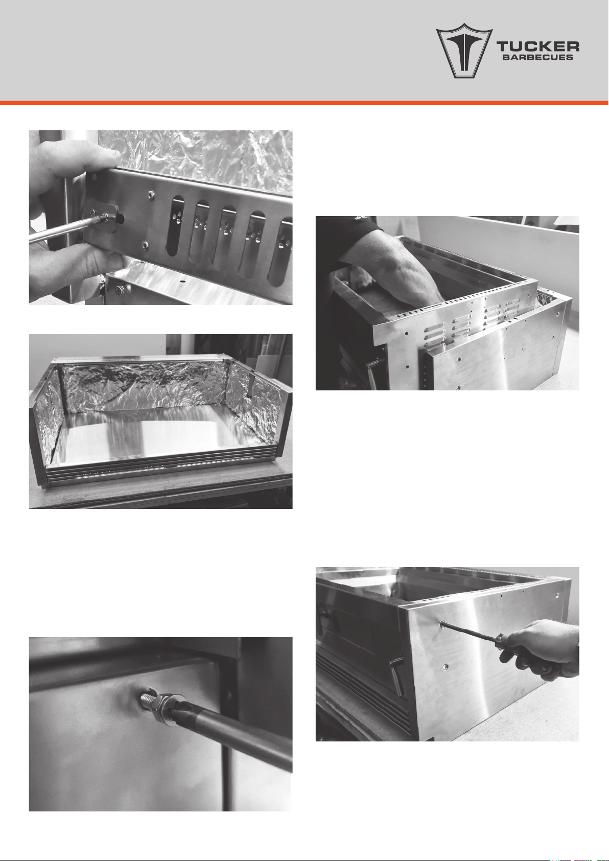
• Remove all plastic protection lm from
stainless steel components before assembly.
• Keep this manual for future reference.
• Read all instructions carefully before
assembly and usage of barbecue/insulation
jacket.
• Clean your barbecue regularly; check the
grease trays for excess grease build up as
damage by grease or fat re is not covered
by warranty.
• Always check that the re has died off when
nishing barbecuing.
• A canvas cover for this barbecue will extend
its life and ensure trouble free operation.
• Attend an operating barbecue at all times.
• Do not use this appliance indoors or in any
enclosed area.
• Do not spray aerosols in the vicinity of this
appliance while it is in operation.
• Do not place articles on or against this
appliance.
WARNING FOR
YOUR SAFETY
• Placing to much charcoal in the barbecue
can result in a huge re that can damage
the BBQ and cause danger.
• Charcoal BBQs burn oxygen and release
carbon monoxide along with other harmful
gases that can kill or make you very sick, it
only takes a couple of hand lls of charcoal
burning in a small room to kill, make sure
you never use the BBQ indoors.
• The BBQ is very hot when it is in use, do not
use the BBQ up against or closer than 1m to
any combustible surfaces.
• It is advisable to place something non-
combustible such as pavers or tiles in front
of the BBQ just in case hot coals roll out by
accident when relling the re box.
• When looking for a place to set up your
Charcoal BBQ outside think about the
surroundings around it.
• Look for a safe place away from bushes
or overhanging trees or other possible re
hazards.
• Do not use or store ammable materials in or
near this appliance.
• Do not modify this appliance in any way.
• Do not allow children to operate the
barbecue.
• Always open the Lid or Roasting Hood before
lighting.
• Do not stack the charcoal up; a single layer
of charcoal will provide plenty of heat to
cook enough food for a standard family
meal.
HAZARDOUS FIRE OR EXPLOSION MAY
RESULT IF INSTRUCTIONS ARE IGNORED.
It is the consumer’s responsibility to see that the
barbecue is properly assembled, installed and
taken care of. Failure to follow the instructions in
this manual could result in serious bodily injury
and /or property damage.

3
INSULATION JACKET
ASSEMBLY INSTRUCTIONS
• Remove the pallet and any plastic lm protecting
or covering any parts of the Insulation Jacket.
• Cut away any packaging or cable ties that may
be holding components in place.
• Check you have all the correct components as
listed in this Page.
10mm spanner
Phillips head screwdriver
TOOLS REQUIRED FOR ASSEMBLY
INSULATION JACKET PARTS
1x Rear Back Panel Filler
1x Base Panel
1x Grease/Ash Tray Louvered Fascia
8x
65mm x M6
Phillips Head Bolts
4x
15mm x M6
Round Head Bolts
7x
M6 Nuts
9x
7mm Spacer
Washers
2x
M4 Nuts
2x
20mm x M4
Round Head Bolts
14x
15mm x M6
Phillips Head Bolts
1x
Left Side
Panel
1x
Left Rotisserie
Arm Hole Cover
1x
Right Rotisserie
Arm Hole Cover
1x
Right Side
Panel
1x Back Panel

4
Charcoal Deluxe Insulation Jacket
Assembly
1. Place the base panel onto your work surface with
the stainless steel side face down and remove
the foil insulation from the base panel.
2. Once the insulation is removed you can see
and access the 6 x holes that you need to use
to screw the 15mm phillips head bolts through to
attach the side panels to the base panel.
3. The next step is to attach the back panel to the
ends of the side panels, you will need to screw 2
x 15mm phillips head bolts with a 7mm spacer on
each bolt into the two holes in the back vertical
ends of each side panel.
The side panels have a small square notch
cut out which signies the front of the side
panels, the front of the base panel has 2 small
holes on the front edge which also signies the
front. When you attach the base panel to the
side panels, the base panel needs to have
the stainless steel side facing up and the side
panels have the insulation facing inward.

5
4. Now you can attach the back panel to the side
panels. Line up the bolt heads on the back of the
side panels with the key holes in each corner of
the back panel and push the back panel down
over the bolt heads which will locate the back
panel into position.
The top of the back panel should be ush with
the top of the side panels when it is in position
correctly.
5. The next step is to secure the back panel to
the base panel using a 15mm phillips head bolt
xed through the middle of the base panel and
through into the bottom of the back panel.
6. Now you can replace the insulation back into the
base panel.
7. The next step is to attach the rear ller panel
to the top of the back panel. You will need to
attach 3 x phillips head bolts and nuts with a
small 7mm spacer/ washer under the head of
the bolts to the rear ller panel as per the photo.

6
8. Now you are ready to attach the rear ller panel.
Line up the key hole slots on the rear panel with
the bolt heads on the back panel, now locate
them over the bolt heads and push the rear ller
panel down locking it into position.

7
10. Next take the ash/grease tray fascia and remove
the protective cover from the pins on each end
of it. Be careful not to lose the small spacer sitting
on the end of each pin.
11. Now locate the right hand side pin into the hole
in the front of the right hand side panel.
12. Now using a phillips head screwdriver loosen the
two phillips head bolts on the back side of the
left hand side of the fascia panel.
By loosening these two bolts it allows the locating
pin on the left hand side of the fascia panel to
slide backwards enough so that you can easily
slide the fascia panel into position and then slide
it back again locating the pin into the hole on
the left hand side panel and then tighten it back
up to lock it in position.
9. Next is the attachment of the grease / ash tray
fascia to the front of the insulation jacket, before
you do this, using the 2 x 20mm bolts and nuts ,
screw one into each side of the base panel at
the front of the jacket.
These bolts are used for adjusting the position the
fascia panel stops at, screwing them in or out will
change the position the fascia sits vertically.

8
13. Now behind the grease /ash tray fascia you can
adjust the position the fascia sits into the jacket
vertically by using the two bolts and nuts you
installed earlier. Simply screw the bolts in or out
and once you are happy with the position the
fascia sits, simply tighten the nut.
15. Remove the grease /ash tray from the BBQ and
lower the BBQ into the jacket.
To secure the BBQ into the Insulation Jacket use
the 8 x 65mm bolts and push them through the
four holes on either side of the Insulation Jacket
side panels.
You need to line the ends of the bolts up to the
nuts that are welded into the side panels of the
BBQ. Once you have them all lined up start to
tighten the bolts rotating the tightening around
the sides of the jacket a little bit on each bolt at
a time.
14. The Insulation Jacket is now complete and ready
for the charcoal deluxe BBQ to be inserted into.

9
16. The last thing to do is to slide the grease/ash tray
back into the BBQ.
The grease / ash tray has an adjustable height
front fascia on it, which is helpful over time as
the heat from the ash will cause the tray to
expand and contract.
The adjustment bolts allow you change the
height of the fascia so as to help make sliding
the tray in and out easier.
To adjust the height simply loosen the bolts
move the fascia by hand and then tighten the
bolts back up again.
Do not use a drill to tighten any nuts and bolts
together in the Insulation Jacket assembly.
Using a drill to tighten them together makes
them hot and will cause them to bind on
each other and get stuck.

10
INSTALLATION INSTRUCTIONS
& WARNINGS
INSTALLATION INSTRUCTIONS
INSTALLATION WARNINGS
READ THE IMPORTANT INFORMATION
ON THE FRONT OF THE BARBECUE
This barbecue and Insulation Jacket are designed
and approved for outdoor use only.
Be mindful of the location of the installation of the
barbecue.
If you are using the roasting hood it is better that the
prevailing wind blows into the front of the BBQ during
cooking.
Do not use this appliance indoors or on marine craft.
This appliance shall only be used in an above
ground, open-air situation with natural ventilation,
without stagnant areas where gas leakage and
products of combustion are rapidly dispersed by
wind and natural convection.
Any enclosure in which the appliance is used shall
comply with one of the following:
• An enclosure with walls on all sides, but at least
one permanent opening at ground level and no
overhead cover. (gure 1)
• Within a partial enclosure that includes an
overhead enclosure and no more than two walls.
(gure 2 and 3)
• Within a partial enclosure that includes an
overhead cover and more than two walls, the
following shall apply. (gures 4 and 5)
• At least 25% of the total wall area is completely
open.
• At least 30% of the remaining wall area is open
and unrestricted.
• In the case of balconies, at least 20% of the total
of the side, back and front wall areas shall be
and remain open and unrestricted.
Strong winds blowing into the back or across the
back of the hood whilst cooking with the hood
closed can cause overheating of the BBQ.
Hot air retained in the hood during cooking may
not be able to be released naturally from the
rear vent of the hood in strong winds.
DIAGRAMMATICAL REPRESENTATIONS OF
OUTDOOR AREAS
FIGURE F1 – OUTDOOR AREA – EXAMPLE 1
FIGURE F2 – OUTDOOR AREA – EXAMPLE 2
FIGURE F3 – OUTDOOR AREA – EXAMPLE 3
The following gures are diagrammatical
representations of outdoor areas. The areas
used in the gures below are examples – the
same principles apply to any other shaped
area.
Both ends open

11
FIGURE 4 OUTDOOR AREA –EXAMPLE 4
FIGURE F5 – OUTDOOR AREA – EXAMPLE 5
Open side at least 25%
of total wall area
30% or more in total of
the remaining wall
area is open and
unrestricted.
OPEN AT SIDE AT LEAST 25% OF TOTAL WALL AREA. 30% OR
MORE IN TOTAL OF THE REMAINING WALL AREA IS OPEN
AND UNRESTRICTED
OPEN SIDE AT LEAST 25% OF TOTAL WALL AREA. 30% OR
MORE IN TOTAL OF THE REMAINING WALL AREA IS OPEN
AND UNRESTRICTED.
Open side at least 25%
of total wall area
30% or more in total of
the remaining wall area
is open and unrestrict-
ed.

Insulation Jacket Fit
12
CHARCOAL DELUXE INSULATION JACKET
DIMENSIONS
DIMENSIONS
Charcoal Deluxe Insulation Jackets are made to reduce the temperature surrounding the barbecue, this enables
the barbecue to be built into an outdoor kitchen using standard building materials.
The Jacket has been designed, so that the base of the insulation jacket can be hidden behind the cabinet doors.
The base panel is thicker to reduce the massive heat radiating from the coals. The insulation base panel is hidden
when the doors are closed.
920mm
30mm
920mm
80mm
40mm
600mm
680mm
600mm
320mm
320mm
280mm
280mm
280mm
600mm
560mm
525mm
540mm
670mm
40mm
80mm
NOTE
When Roasting hood is shut handle will
pass front panel by 15mm this makes the
hood to be 570mm deep.
2
2
- Height of Lid when closed is 40mm
- Height of lid when open is 670mm
- Flat roll down Lid can drop below
the base of the BBQ body by 190mm
when opened and lowered down to its
maximum roll down depth.
- Height of Lid when closed is 40mm
- Height of lid when open is 540mm
Roll Down Flat Lid Height
Hinge Flat Lid Height

13
CHARCOAL DELUXE INSULATION JACKET
BUILT-IN CUT-OUT DIMENSIONS
Clearances above BBQ cooking surface to
combustible walls are as follows:
925mm
280mm
320mm
600-680mm
40mm
IMPORTANT
Clearance to rear walls 1000mm
Clearance to side walls 1000mm
Clearance above the BBQ cooking surface 1200mm
The insulation jacket is designed to offer zero
clearance to combustible materials that can
withstand continuous temperatures of 100oC for 24
hours continuously.
It is important that you check with your material
supplier if the material used can withstand 100oC for
24 hours continuously.

14
WARRANTY
TUCKER CHARCOAL DELUXE INSULATION
JACKET WARRANTY
WARRANTY PERIOD
NOT COVERED
CONDITIONS OF THIS WARRANTY
Stainless steel body 10 years
The warranty does not cover the purchaser or any
other person for damage malfunction or loss due to
the following:
• Lack of maintenance, abuse, neglect, misuse,
accident, or improper installation of this
appliance.
• Scratches, dents or discoloration caused by heat,
abrasive or chemical cleaners.
• Damage due to grease or fat res.
• Surface rust.
• Cleaning and normal wear and tear.
• Unauthorized repairs during the warranty period.
SERVICE CALLS OF THE ABOVE NATURE ARE
CHARGEABLE
1. The appliance is delivered to TUCKER AUSTRALIA
distributors service department or authorized
service agent and freight charges both ways is to
be paid by the owner. No liability is accepted for
loss or damage during transit.
2. The appliance is installed by a qualied person
and operated and maintained in accordance
with the instructions supplied. Repairs and service
must be carried out by an authorized person.
3. Installation must conform to the standards laid
down by the local codes or, in the absence of
local codes, with AGA code AG:601
AS:5601:2002
4. No alterations or repairs are to be carried out
without obtaining the distributors prior consent.
Such repair or any replacement does not extend
the warranty period.
5. Proof of purchase together with this warranty
must be provided to verify purchase date and
establish the warranty period. Only the original
purchaser is covered under this warranty.
6. Where this warranty is inconsistent with any state
laws, the rights of the purchaser shall prevail.
7. Parts installed from other manufacturer’s
products will nullify this warranty.
FOR YOUR RECORDS
Model:
Serial Number:
Retailer:
Purchase Date:
TUCKER AUSTRALIA PTY LTD.
138 Silverwater Road
Silverwater NSW 2128 AUSTRALIA.
PHONE: (+612) 9748 8368
FAX: (+612) 9748 8138
WEB SITE: www.tuckerbbq.com.au
EMAIL: [email protected]

15
NOTES

16

TUCKER AUSTRALIA PTY LTD.
138 Silverwater Road
Silverwater NSW 2128 AUSTRALIA.
PHONE: (+612) 9748 8368
FAX: (+612) 9748 8138
WEB SITE: www.tuckerbbq.com.au
EMAIL: [email protected]
Table of contents
Other Tucker Barbecues Kitchen Appliance manuals
Popular Kitchen Appliance manuals by other brands

Cuizimate
Cuizimate RBSEGGBOILERWHP instruction manual

KitchenAid
KitchenAid 5SSA Instructions and recipes

Vorwerk
Vorwerk Thermomix TM5 instruction manual

emerio
emerio ST-111153.4 instruction manual

MACAP
MACAP P507 manual

Next Cooking Generation
Next Cooking Generation Waveco USE, MAINTENANCE AND INSTRUCTIONS MANUAL