Tuff TNT-503021E User manual

■TNT-503021E ■TNT-503531E ■TNT-603531E ■TNT-503061E
■TNT-503021E/G ■TNT-503531EG ■TNT-603531E/G ■TNT-503061E/G
TNT
OPERATOR’S MANUAL
TUFF PRESSURE WASHERS ■ 659 Randall Wobbe Ln. ■ Sprindale, AZ 72764 ■ USA
For technical assistance or theTUFF Dealer nearest you, call 1-800-772-8833.

CONTENTS
2
TUFF TNT Manual • Form #XX-XXXX • Revised 7/01
ModelNumber ______________________________
Serial Number______________________________
Date of Purchase ____________________________
The model and serial numbers will be found on a decal attached to
the pressure washer.You should record both serial number and
date of purchase and keep in a safe place for future reference.
Introduction...................................................................................................................................3
Important Safety Information.....................................................................................................3, 5
ComponentIdentification ..............................................................................................................4
Pre-Operation Check ....................................................................................................................5
Set-Up Procedures ....................................................................................................................5-6
Operating Instructions...................................................................................................................6
GeneralWashingTechniques........................................................................................................6
Shut Down Procedures.................................................................................................................6
HowTo Use The Detergent Injector ..............................................................................................7
Preventative Maintenance.............................................................................................................8
Maintenance and Service ..........................................................................................................8-9
ExplodedView, Left Side.............................................................................................................10
ExplodedView, Right Side ..........................................................................................................11
Parts List................................................................................................................................12-14
FloatTank Assembly, Exploded View and Parts List ...................................................................15
Control Panel, ExplodedView .....................................................................................................16
Control Panel, Parts List .............................................................................................................17
Burner Assembly and Parts List..................................................................................................18
Hose and Spray Gun Assembly and Parts List ...........................................................................19
Troubleshooting .....................................................................................................................20-23
Maintenance Chart .....................................................................................................................24
Oil Change Record .....................................................................................................................24
Warranty .....................................................................................................................................25

TNT SERIES PRESSUREWASHER OPERATOR’S MANUAL
3
INTRODUCTION
Thank you for purchasing aTNT Pressure Washer.
This manual covers the operation and maintenance of
theTNT-503021E,TNT-503021E/G,TNT-503531E,TNT-
503531E/G, TNT-603531E, TNT-603531E/G, TNT-
503061E and TNT-503061E/G washers.All information
inthis manualis basedon thelatest product information
available at the time of printing.
Landa, Inc. reserves the right to make changes at any
time without incurring any obligation.
TheTNT Series was designed for maximum
use of 8 hours per day, 5 days per week.
Owner/User Responsibility:
The owner and/or user must have an understanding of
the manufacturer’s operating instructions and warnings
beforeusing thisLanda pressurewasher.Warning infor-
mationshould beemphasizedandunderstood.Ifthe op-
eratoris notfluent inEnglish, themanufacturer’sinstruc-
tions and warnings shall be read to and discussed with
the operator in the operator’s native language by the
purchaser/owner, making sure that the operator com-
prehends its contents.
Owner and/or user must study and maintain for future
reference the manufacturers’instructions.
This manual should be considered a permanent
part of the machine and should remain with it if
machine is resold.
When ordering parts, please specify model and
serial number.
IMPORTANT SAFETY
INFORMATION
WARNING:Whenusingthisproductbasicprecautions
should always be followed,including the following:
CAUTION: To reduce the risk of
injury, read operating instruc-
tions carefully before using.
1. Readthe owner’s manualthor-
oughly. Failuretofollowinstruc-
tionscouldcausea malfunction
of the machine and result in
death,seriousbodily injuryand/
or property damage.
2. Knowhow tostop themachine andbleedpressures
quickly.Be thoroughly familiar with the controls.
3. Stay alert — watch what you are doing.
4. All installations must comply with local codes. Con-
tact your electrician, plumber, utility company or the
selling distributor for specific details.
WARNING: Risk of asphyxiation.
Use this product only in a well
ventilated area.
5. Avoid installing machines in
small areas or near exhaust
fans.Exhaust contains poison-
ous carbon monoxide gas; ex-
posure may cause loss of con-
sciousness and may lead to
death. It also contains chemi-
cals known in certain quantities, to cause cancer,
birth defects, or other reproductive harm.
WARNING:Flammableliquidscan
create fumes which can ignite,
causing property damage or se-
vere injury.
CAUTION:Risk of fire.Do not add
fuelwhentheproductisoperating.
6. Allow engine to cool for 2 min-
utesbeforerefueling.Ifanyfuel
is spilled, make sure the area
is dry before testing the spark plug or starting the en-
gine.(Fireand/orexplosionmayoccurifthisisnotdone.)
Gasoline engines on mobile or portable equipment
shall be refueled:
(a) outdoors;
(b) with the engine on the equipment stopped;
(c) with no source of ignition, within 10 feet of the
dispensingpoint; and
(d) with anallowancemade for expansion ofthefuel
should the equipment be exposed to a higher
ambienttemperature.
In an overfilling situation, additional precautions are
necessary to ensure that the situation is handled in
an safe manner.
WARNING: Risk of explosion –do not spray flam-
mable liquids.
7. Do not place machine near flammable objects as
the engine is hot.
WARNING:Risk ofinjection or se-
vereinjuryto persons - Keepclear
of nozzle - Do not touch or direct
dischargestreamat persons.This
machine is to be used only by
trained operators.
CAUTION: Hotdischargefluid.Do
not touch or direct discharge
stream at persons.
WARNING
RISK OF
ASPHYXIATION.
USE THIS PRODUCT
ONLY IN A WELL
VENTILATED AREA.
WARNING
READ OPERATOR’S
MANUAL
THOROUGHLY
PRIORTO USE.
WARNING
HIGH PRESSURE
STREAM CAN
PIERCE SKIN AND
TISSUES.
CAUTION
RISK OF EXPLOSION:
DO NOT USE WITH
FLAMMABLE
LIQUIDS.
WARNING

4
TNT SERIES PRESSUREWASHER OPERATOR’S MANUAL
COMPONENT IDENTIFICATION

TNT SERIES PRESSUREWASHER OPERATOR’S MANUAL
5
8. Highpressuredevelopedbythesemachineswillcause
personal injury or equipment damage. Use caution
when operating. Do not direct discharge stream at
people, or severe injury or death will result.
WARNING: High pressure spray
can cause paint chips or other
particles to become airborne and
fly at high speeds.
9. Eye safety devices, safety
clothing and foot protection
must be worn when using this
equipment.
10. Never make adjustments on
machinewhile itisin operation.
WARNING: Spray gun kicks back. Hold with both
hands.
11. Grip cleaningwand securelywith bothhands before
starting the cleaner.Failure to do this could result in
injury from a whipping wand.
12. Machineswith spraygun shouldnotbeoperatedwith
the spray gun in the off position for extensive peri-
ods of time as this may cause damage to the pump.
13. The best insurance against an accident is precau-
tion and knowledge of the machine.
14. TUFF will not be liable for any changes made to our
standard machines, or any components not pur-
chased fromTUFF.
WARNING:Keep wand,hose and
water spray away from electrical
wiring or fatal electric shock may
result.
15. Readengine safetyinstructions
provided.
16. Never run pump dry or leave
spray gun closed longer than 5
minutes.
17. Inlet water must be cold and clean fresh water.
18. Use No. 1 or No. 2 Heating Oil (ASTM D306) only.
NEVER use gasoline in your fuel oil tank.Gasoline
is more combustible than fuel oil and could result in
aserious explosion.NEVER usecrankcaseor waste
oil in your burner. Fuel unit malfunction could result
fromcontamination.
19. Do not confuse gasoline and fuel oil tanks. Keep
proper fuel in proper tank.
20. Protect machine from freezing.
21. Be certain all quick coupler fittings are secured be-
fore using pressure washer.
22. Donot allowacids,caustic,or abrasive fluidsto pass
through the pump.
23. To reducethe risk ofinjury,close supervisionis nec-
essarywhen aproduct is usednear children.Do not
allow children to operate the pressure washer.This
machine must be attended during operation.
24. Do not operate this product when fatigued or under
theinfluenceofalcoholor drugs.Keepoperatingarea
clear of all persons.
25. Protectdischarge hosefromvehicletrafficand sharp
objects.Inspect condition of high pressure hose be-
fore using or bodily injury may result.
26. Beforedisconnecting dischargehosefromwaterout-
let, turn burner off and open spray gun to allow wa-
tertocool below100°Fbeforestopping themachine.
Thenopen thespraygunto relievepressure.Failure
to properly cool down or maintain the heating coil
may result in a steam explosion.
27. TUFF will not be liable for any changes made to our
standard machines or any components not pur-
chased fromTUFF.
28. Donot overreach orstandonunstablesupport.Keep
good footing and balance at all times.
29. This machine must be attended during operation.
30.
CAUTION: Risk of injury. Disconnect battery
ground terminal before servicing.
PRE-OPERATION CHECK
❑Pump oil (SAE 30W non-detergent oil, General)
❑Cold water supply (6 gpm • 58" • 20 psi)
❑Hose, wand, nozzle (nozzle size per serial plate)
❑Water filter (intact, non restrictive)
❑Engine fuel (unleaded 86 or higher octane)
❑Engine oil (SAE 10W30)
❑Burner fuel (No.1 home heating fuel or diesel)
SET-UP PROCEDURES
This machine is intended for outdoor use only.
Machine must be stored indoors when not in use.
1. Attach a 5/8" water supply hose to inlet connector.
Minimum flow should be 6 or 10 gpm depending on
model of machine.
2. Attach highpressure hoseto dischargenippleusing
quick coupler. Lock coupler securely into place by
pulling back coupler collar and inserting it into dis-
charge nipple, then pushing collar forward to lock in
place.
3. Attach variable pressure control wand to spray gun
using teflon tape on threads to prevent leakage.
4. Attach swivel connector on discharge hose to spray
gun using teflon tape on threads.
WARNING
USE PROTECTIVE
EYE WEAR
AND CLOTHING
WHEN OPERATING
THIS EQUIPMENT.
WARNING
KEEP WATER
SPRAY AWAY FROM
ELECTRICALWIRING.

6
TNT SERIES PRESSUREWASHER OPERATOR’S MANUAL
5. Check engineandpump oillevel byremovingoil dip-
stick,making sureoil ison properindicator marking.
Oilshouldbevisibleone halfwayupsight glass(SAE
30Wnon-detergent).
6. Fill red gasoline tank.
7. Fill greenfueltank.Donot confusegasoline andfuel
oil (diesel) tanks.Keep proper fuel in proper tank.
8. Install properbattery making sure thatthe red cable
isattached tothepositiveterminal.Use a12VGroup
24 battery.
OPERATING INSTRUCTIONS
1. Read engine warning and operating instructions.
2. Turnonwateratfaucet.Checkforwaterleaks;tighten
as needed.
3. Pull wandcouplercollarbackandinsertdesired pres-
sure nozzle into wand coupler then secure by push-
ing coupler collar forward.
NOTE: Variable pressure control wand handle must
be turned clockwise to enable water to flow out of
the high pressure nozzle.
4. Pull spray gun trigger to relieve pressure.Read en-
gine manual provided and pull choke. Turn engine
switch to the START position and hold it there until
the engine starts. NOTE: Do not engage electric
starter for more than five (5) seconds at a time. If
engine fails to start, release the switch, pull spray
guntriggerto relievepressure and waitten seconds
before operating the start again. When the engine
starts, allow the engine switch to return to the ON
position. If the engine is to be started without the
battery, turn switch to start position and pull starter
grip to start.Turn off choke.
CAUTION:Small engines may kick back.Do not hold
starter grip tightly in hand.
5. With thespray nozzlepointed awayfromyouor any-
body else, press the trigger on the spray gun to ob-
tain pressurized cold water spray.
6. For hot water, turn the burner switch to ON when a
steady stream of water flows out of the spray gun.
Burner will now light automatically.
NOTE: Do not start machine with burner switch on.
7. Toapply detergent,placedetergent pick-uptube into
acontainer ofdetergentand turn thedetergentvalve
counter clockwise (see page 4).
GENERALWASHING
TECHNIQUES
1. Hold spray nozzle approximately one foot from the
surface being cleaned.Spray at an angle to get un-
der the material and lift it off.
2. When detergentis requiredforcleaning, start wash-
ing from the bottom and work up. Better detergent
economy and faster results will be obtained by al-
lowingthechemical toset 5-10minutes.Afterwash-
ing, rinse from the top down.
3. Cleaning heavy dirt or material away with a hard
stream of clear water is recommended before using
a cleaning agent.
SHUT DOWN PROCEDURES
1. Rinse alldetergent lineswith cleanwater, toremove
any soap residue.
2. Turn burner switch off and continue spraying, allow-
ing the water to cool to below 100°F.
3. Turn engine key switch off.
4. Turn off water supply.
5. Squeeze trigger on spray gun to relieve remaining
pressure.
6. Remove water supply hose.
7. In freezing conditions, disconnect water, drain float
tank and add a 50/50 mixture of anti-freeze. Start
the machine and squeeze trigger on spray gun to
allow the mixture to flow out of the wand. Now turn
offtheengine.SeewinterizingprocedureunderMain-
tenance and Service.
CAUTION: Do not allow pump to
run longer than 5 minutes with-
outwater.Disconnect allhoses to
allow water to drain.
With machine off,open spray gun
torelease pressurebeforeremov-
ing discharge hose.
WARNING: Some detergents may
be harmful if inhaled or ingested,
causing severe nausea, fainting or poisoning. The
harmful elements may cause property damage or se-
vere injury.
WARNING
RISK OF
ASPHYXIATION.
USETHIS PRODUCT
ONLY IN AWELL
VENTILATED AREA.

TNT SERIES PRESSUREWASHER OPERATOR’S MANUAL
7
HOWTO USETHE OPTIONAL
DETERGENT INJECTOR
The machine can siphon and mix detergents with the use
of Landa's detergent injector kit.
1. Pullinjector quickcouplercollar backand secureon
discharge nipple. Injector valve body arrow should
point in direction of flow.
2. Connect high pressure hose to injector discharge
nipple securing quick coupler.
3. Start machine as outlined in Operating Instructions.
4. Place detergentpick-uptubeinto containerof deter-
gent.
5. Turn pressure control handle counterclockwise on
the variable pressure wand. This lowers the pres-
sure by directing the water flow through the soap
nozzle and allows the detergent injector to siphon
soap.
6. Open spray gun. Water detergent ratio is approxi-
mately 15 to 1.
7. When you finish washing, rinse by simply turning
thevariablepressure wandcontrol handleclockwise
to increase pressure.
NOTE: The detergent injector will not siphon deter-
gent with the water flowing through the high pres-
sure nozzle at the end of the wand.
8. Forclean up,place detergentc v tubeinto container
of clear water and follow steps 4 and 5 to prevent
detergent deposits from damaging the injector.
Detergent Injector
Discharge
Nipple
Quick
Coupler
High Pressure
Nozzle
Variable Pressure
Control Wand Handle
Spray Gun
Detergent
Bucket (Not
Included)
Detergent
Pickup Tube
Detergent
Bucket (Not
Included)
Soap Nozzle

8
TNT SERIES PRESSUREWASHER OPERATOR’S MANUAL
PREVENTATIVE MAINTENANCE
1. Checkto seethatwater pumpis properly lubricated.
2. Followwinterizinginstructionstopreventfreezedam-
age to pump and coils.
3. Always neutralize and flush detergent from system
after use.
4. If waterisknown tobe highinmineral content,use a
watersoftener onyourwater system,or de-scaleas
needed.
5. Do not allow acidic, caustic or abrasive fluids to be
pumped through system.
6. Always use high grade quality cleaning products.
7. Never run pump dry for extended periods of time.
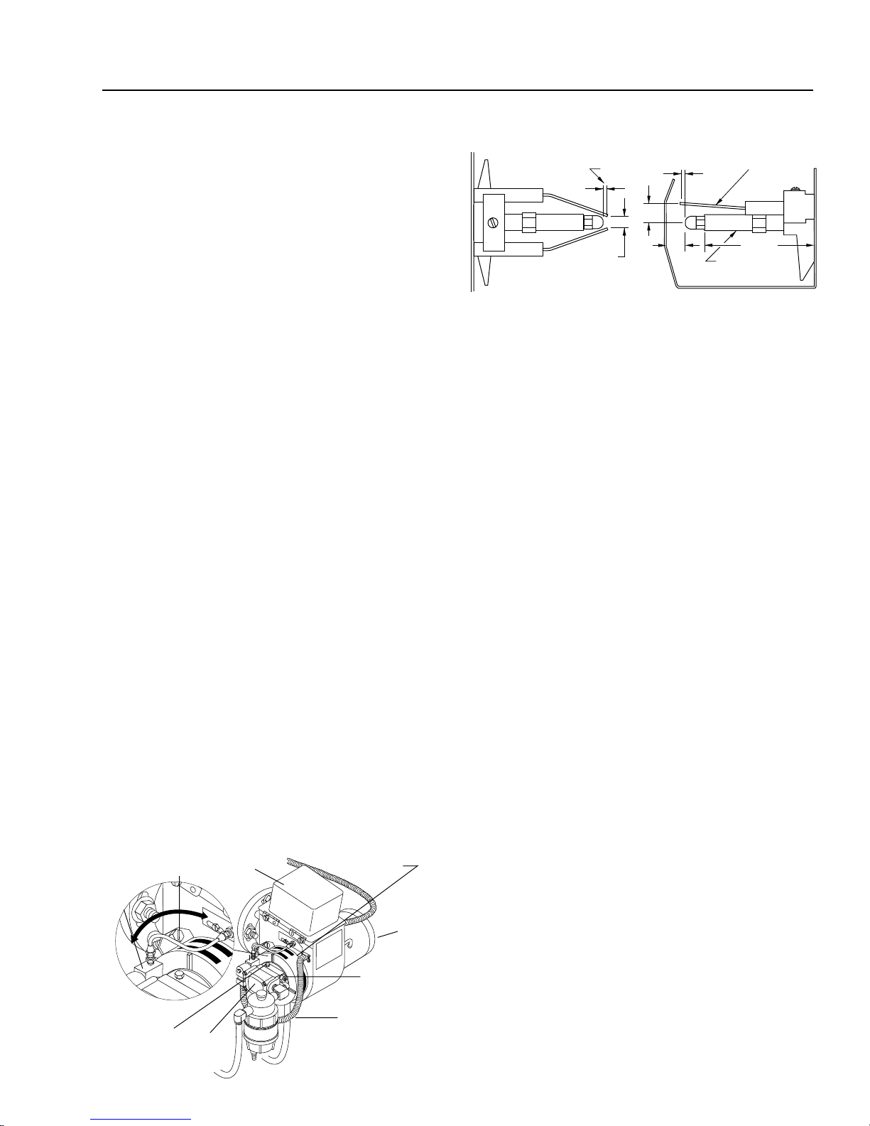
8. Use clean fuel-kerosene, No. 1 fuel oil, or diesel.
Cleanor replacefuel filterevery100 hoursof opera-
tion.Avoidwater contaminatedfuel asitwill damage
the fuel pump.
9. If machine is operated with smoky or eye burning
exhaust, coils will soot up, not letting water reach
maximumoperatingtemperature.
10. Never allowwatertobesprayedonornear theengine
or burner assembly or any electrical component.
11. Periodically delime coils as per instructions.
12. Check to see that engine is properly lubricated.
It is advisable, periodically, to visually inspect the burner.
Check air inlet to make sure it is not clogged or blocked.
Wipe off any oil spills and keep equipment clean and dry.
The flow of combustion and ventilating air to the burner
must not be blocked or obstructed in any manner.
Thearea aroundtheLanda washershould bekeptclean
and free of combustible materials, gasoline and other
flammable vapors and liquids.
MAINTENANCE AND SERVICE
Unloader Valves:
Unloader valves are preset and tested at the factory be-
foreshipping.Occasional adjustmentoftheunloadermay
be necessary to maintain correct pressure.
Winterizing Procedure:
Damage due to freezing is not covered by warranty.Ad-
hereto thefollowingcold weatherprocedures whenever
the washer must be stored or operated outdoors under
freezing conditions.
During winter months, when temperatures drop below
32°F, protecting your machine against freezing is nec-
essary.Store the machine in a heated room.If this is not
possible then mix a 50/50 solution of anti-freeze and
water in the float tank.Turn the engine on to siphon the
anti-freeze mixture through the machine.If compressed
airis available,anair fitting canbe screwed intothe float
tank by removing the float tank strainer and fitting.Then
inject the compressed air.Water will be blown out of the
machine when the trigger on the spray gun is opened.
High Limit Hot WaterThermostat:
For safety, each machine is equipped with a tempera-
ture sensitive high limit control switch. In the event that
the water should exceed its operating temperature, the
high limit control will turn the burner off until the water
coolsthen automaticallyreset itself.Thethermostatsen-
sor is located on the discharge side of the heating coil.
Thethermostatcontroldial islocatedon thecontrol panel.
Pumps:
Use only SAE 30 weight non-detergent oil. Change oil
after first 50 hours of use.Thereafter, change oil every
threemonths orat 500hour intervals.Oil levelshould be
checked through use of dipstick found on top of pump,
or the red dot visible through the oil gauge window. Oil
should be maintained at that level.
Cleaning of Coils:
In alkaline water areas, lime deposits can accumulate
rapidly inside the heating coil.This growth is increased
bytheextremeheat buildup inthe coil.Thebest preven-
tativeforliming conditionsis touse highquality cleaning
detergents.In areas where alkaline water is an extreme
problem,periodicuse ofLandaDelimingPowder(C-Tech
Part #9-028008) will remove lime and other deposits
beforecoil becomesplugged.(See Deliminginstructions
for use of Landa Deliming Powder.)
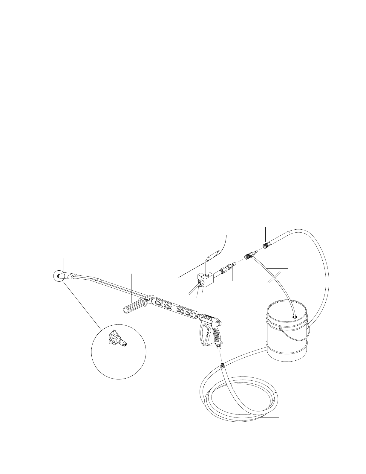
Deliming Coils:
Periodicflushing ofcoilsoroptional floattankisrecommended.
Step 1 Fill a container with 4 gallons of water, then add
1 lb.of deliming powder.Mix thoroughly. Pour
mixture into float tank.
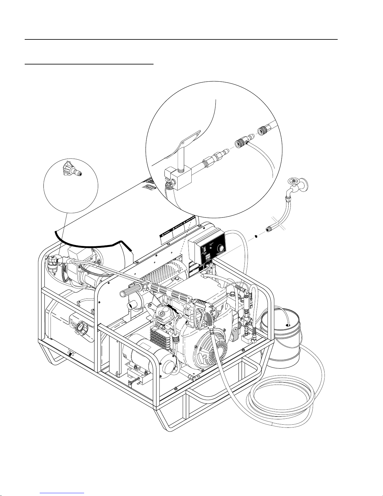
Step 2 Removewandassemblyfromspraygun andput
spray gun into float tank.Secure the trigger on
the spray gun into the open position.
Step 3 Turn engine on, allowing solution to be pumped
through coils back into the float tank.The solu-
tion should be allowed to circulate 2-4 hours or
until the color changes.
Step 4 After circulating solution, flush the entire sys-
tem with fresh water.Clean out float tank and
then reinstall wand assembly to spray gun.
Removal of Soot and Heating Coil:
In the heating process, fuel residue in the form of soot
depositsmaydevelop betweenthe heatingcoil pipeand
block air flow which will affect burner combustion.When
soot has been detected on visual observation, the soot
on the coil must be washed off after following the coil
removal steps (See Coil Removal on page 9).

TNT SERIES PRESSUREWASHER OPERATOR’S MANUAL
9
Rupture Disk:
If pressure from pump or thermal expansion should ex-
ceed safe limits, the rupture disk will burst allowing high
pressuretobe dischargedthroughhoseto ground.When
disk ruptures it will need to be replaced.
Fuel:
Use clean fuel oil that is not contaminated with water
and debris. Replace fuel filter and drain tank every 100
hours of operation.
Use No.1 or No 2 Heating Oil (ASTM D306) only.NEVER
use gasoline in your burner fuel tank. Gasoline is more
combustible than fuel oil and could result in a serious ex-
plosion.NEVER usecrankcaseorwasteoilinyourburner.
Fuel unit malfunction could result from contamination.
Fuel Control System:
This machine utilizes a fuel solenoid valve located on the
fuelpumptocontroltheflowoffueltothecombustioncham-
ber.Thesolenoid, whichisnormallyclosed,isactivatedby
aflowswitchwhenwaterflowsthroughit.Whentheopera-
tor releases the trigger on the spray gun, the flow of water
throughtheflowswitch stops,turningoff theelectricalcur-
rent to the fuel solenoid.
The solenoid then closes, shutting off the supply of fuel to
thecombustionchamber.Controllingtheflowof fuelinthis
way gives an instantaneous burn-or-no-burn situation,
thereby eliminating high and low water temperatures and
thecombustionsmokenormallyassociatedwithmachines
incorporating a spray gun. Periodic inspection, to insure
that the fuel solenoid valve functions properly, is recom-
mended.This can be done by operating the machine and
checkingtoseethatthe burner isnotfiringwhen thespray
gun is in the OFF position.
Fuel Pressure Adjustment:
Tocontrolwatertemperature,adjustfuelpressurebyturn-
ing the regulating pressure adjusting screw clockwise to
increase, counterclockwise to decrease. Do not exceed
200psi. NOTE: Whenchanging fuelpump,abypassplug
mustbe installedinreturnportorfuel pumpwillnot prime.
DC Electrodes Setting
Burner Nozzle:
Keep the tip free of surface deposits by wiping it with a
clean, solvent saturated cloth, being careful not to plug
or enlarge the nozzle.For maximum efficiency, replace
the nozzle each season.
Air Adjustment:
Machines are preset and performance tested at the fac-
tory- elevation100'.A one-timeinitial correctionforyour
location will pay off in economy, performance, and ex-
tended service life.If a smoky or eye-burning exhaust is
being emitted from the stack, two things should be
checked. First, check the fuel to be certain that kero-
sene or No. 1 home heating fuel is being used. Next,
check the air adjustment on the burner.
Coil Removal:
Removal of coil because of freeze breakage, or to clean
soot from it can be done quickly and easily.
1. Disconnect hose from pump to inlet side of the coil.
2. Carefully disconnect the thermostat sensor making
sure you do not crimp the capillary tube.
3. Removeburner assemblyfromcombustionchamber.
4. Remove the 3-3/8 bolts from each side of coil and
tank assembly (these bolts are used to fasten tank
to chassis).
5. Remove fittings connected to the 1/2" pipe nipples
from inlet and discharge sides of coil.
6. Remove top tank wrap, bend back insulation tabs
and fold back blanket.
7. Remove bolts that hold down coil to bottom wrap.
8. Remove coil.
9. Replace or repair any insulation found to be torn or
broken.
10. Remove insulation retainer plates.
Coil Reinstallation:
Reinstall new or cleaned coil reversing Steps 9 through 1.
Gap
1/8" 1/8"
3/8"
1/2"
3/16"
Top View Side View
Nozzle
Adapter
2-7/8"
Periodically CheckWiring Connections. If Necessary
To Adjust Electrodes, Use Diagram.
Air
Adjustment
Screw
#7-0009
Fuel
Pump
#7-3753895
Cord Set
Adjusting
Screw
Pressure
Gauge
Port
Air Band
Motor
#7-0005
Transformer
#7-20358
Electrodes

10
TNT SERIES PRESSUREWASHER OPERATOR’S MANUAL
EXPLODED VIEW
LEFT SIDE

TNT SERIES PRESSUREWASHER OPERATOR’S MANUAL
11
EXPLODED VIEW
RIGHT SIDE

12
TNT SERIES PRESSUREWASHER OPERATOR’S MANUAL
ITEM PART NO. DESCRIPTION QTY
1 95-07200010 Top Wrap, SS, PHW Series II 1
2 2-01104 Trim, 1/16" Black, /ft .6
3 90-1006 Bolt, 5/16" x 3/4" 4
4 2-0031 Elbow, 3/8" Street 1
5 90-1016 Bolt, 3/8" x 1", NC HH 15
6 7-01484 Insulation/Blanket - Die Cut
28" x 24" 1
7 7-01430 Insulation Blanket - No Foil,
24" x 57" 1
8 10-02011 Label, Use only Gasoline 1
9 10-02025A Label, Hot/Caliente 3
10 10-02028 Label, Warning-
Exposed Pulleys 2
11 7-0141 Insulation, Burner Head, w/Hole1
12 95-07121212 Coil Replacement Schedule 80
w/Mild Steel Wrap 1
13 95-07200012 Wrap, Bottom, Stainless Steel 1
14 7-0140 Insulation, Front Head, No Hole1
15 7-12484 Gasket, Standard - Large 1
16 7-0144 Gasket, Burner Plate 2
17 95-07121113 PHW/VNG Insulation
Retainer Plate 2
18 7-00030 Burner Assy, Beckett 12 Volt 1
7-58726 ▲ Electrode Rod & Insulator
Assy 1
7-21441 ▲ Solednoid, Valve, Fuel
12 Volt 1
7-21404 ▲ Wheel, Blower Fan 1
7-21405 ▲ Coupling, Fuel 1
7-0102 ▲ Nozzle, Burner 2.00, 90°, B 1
7-0103 ▲ Nozzle, Burner, 2.25, 90°, B 1
19 2-1022 Elbow, 1/4" Street 1
20 2-1002 Nipple, 1/4" Close 1
21 2-9905 Filter, Fuel/Oil H20 Separator 1
22 90-1019 Bolt, 3/8" x 1-3/4" Tap 3
23 2-9000 Clamp, Screw, #4 7
24 4-02100000 Hose, 1/4", Push-on /ft 14
25 2-1085 Hose Barb, 1/4" Barb x 1/4"
ML Pipe 1
26 2-00120 Nipple, 1/2" x 5" (4-2000, 4-3000,
5-3000, 5-3500) 1
2-00123 Nipple, 1/2"x5" Black Pipe
(4-4000) 2
ITEM PART NO. DESCRIPTION QTY
27 2-00101 Nipple, 1/2" x 3", Galv. 2
28 2-00241 Coupling, 1/2" x 3/8" Reducing 1
29 2-2007 Nipple, 3/8" x 3/8" NPT St Mal 1
2-20022 Nipple, 3/8" Female Fastener 1
30 2-0032 Elbow, 1/2" Street 1
31 2-90041 Clamp Screw #16 1
32 4-05088 Thermostat, General, 302° 1
33 4-02047725 Hose, 25" x 3/8", 100R2,
Pres Loop 1
34 4-02047716 Hose, 16" x 3/8", 100R2
Pres Loop 1
35 90-19959 Screw, 3/8" x 1" HX Wash 6
36 90-2001 Nut, 5/16" ESNA 4
37 90-4001 Washer, 5/16" Flat SAE 8
38 2-1089 Hose Barb, 1/4" Barb x 1/4"
Pipe, 90° 3
39 2-1037 Tee, 1/4" Branch Male 1
40 2-1076 Bushing, 1/2" x 1/4" Pipe 1
41 2-11080 Push-on 3/4" x 1/2" Male 1
42 4-02120000 Hose, 3/4", Push-on /ft. 1.3
43 5-3208 Unloader, AR, AL607 1
44 2-00101 Nipple, 1/2" x 4" Gal Sch 80 1
45 2-1060 Elbow, 1/2" JIC x 3/8" 90° 3
46 95-07101226 Discharge Block, 1/2" 1
47 90-1020 Bolt, 3/8" x 2", NC HH 2
48 95-07101216/B Block, Unloader, 3/8" x 3/8" Brass 1
49 4-02130050 Hose, Conduit 7/8" /ft. 2
50 10-02029 Label, Danger Cool Engine 1
51 2-0079 Swivel, 1/2" JIC x 3/8" Male 1
52 2-0051 Nipple, 1/2" JIC x 3/8" Pipe 1
53 90-1011 Bolt, 5/16" x 2", NC HH 4
54 2-10730 Elbow, 3/4" JIC x 1/2", 90° 1
55 2-1105 Swivel, 1/2" JIC Fem, Push-on 4
56 4-02110000 Hose, 1/2" Push-on /ft. 1.5
57 2-1062 Elbow, 1/2" JIC x 1/2" 90° 1
58 2-0053 Elbow, 1/2" JIC, 3/8" 90° 2
59 2-1035 Cross, 1/2" Female, Pipe 1
60 2-30082 Pump Protector, 1/2" PTP 1
61 2-1007 Nipple, 1/2" Hex 1
62 4-02100030 Inlet Hose, 30" Supply Water 1
63 4-02100013 Inlet Hose, 13" Supply Water 1
EXPLODED VIEW
PARTS LIST

TNT SERIES PRESSUREWASHER OPERATOR’S MANUAL
13
ITEM PART NO. DESCRIPTION QTY
64 2-10712 Tee, 1/2" x 1/2" JIC 51# 1
65 2-1024 Elbow, 1/2" Street, Brass 1
66 6-0601 Generator, Winco (2000 watts) 1
66 6-0107 ▲Cord, Molded, Royal, K1426,
14-3 1
67 2-0006 Nipple, 3/8" Hex 1
68 95-0712112 Rail, Pump or Generator
Combo (PHW/Skid) 2
69 95-07141110
Retainer, PumpTake Up, Plated
2
70 90-10220 Bolt, 3/8" x 3-1/2", Tap 4
90-2020 ▲▲
▲▲
▲Nut, Cage 3/8" x 12 GA 9
90-2007 ▲▲
▲▲
▲Nut, 3/8", HEXNC 4
90-4002 ▲▲
▲▲
▲Washer, 3/8", SAE, Flat 50
71 2-0056 Elbow, 1/2" JIC, 3/8", 90°,
LBG (VAN., 20 HP Honda only) 1
2-1101 ▲▲
▲▲
▲Adaptor, 3/8" x 1/4" (20 HP
Honda only) 1
72 2-1050 Plug, 1/2" JIC, Flare (VAN., 20 HP
Honda only) 1
73 10-99087 Label, Warning 1
74 2-11050 Swivel, 3/4" JIC FEM, Push-on 1
75 5-0107 Engine, Honda, GX340 QAE,
E/S 11 HP (PGHW4-20321E) 1
5-010722 Engine, Honda GX390 KQAE2
13 HP E/S (4-30321E1) 1
5-0309 Engine, Van. 16 HP ES No
Tank (5-30221E) 1
5-0316 Engine, Van. 21 HP E/S
(5-35221E, 4-40221E) 1
5-0105 Engine, Honda, GX340KQAP2
11 HP, Pull Start (4-20321) 1
5-01093 Engine, Honda, GX620K1QB3,
20 HP, 20 Amp E/S (5-35321E) 1
76 76-807964 Muffler, Exhaust Skid,
16 HP Van. 1
76-808597 ▲Muffler, Van. 21 HP 1
77-VHLM4 ▲Muffler, (20 HP Honda) 1
77 95-07101149 Guard, Muffler, Vanguard 1
95-07101153 Guard, Van. 21 HP 1
95-071011491 ▲Brace, Vangrd Muff. Bracket 2
78 5-511063 Bushing, H x 5/8" (Winco only) 1
ITEM PART NO. DESCRIPTION QTY
79 5-40403001 Pulley, BK30H (4-2000) GEN. 1
5-40403201 Pulley BK32H (4-4000, 5-3000,
5-3500) GEN 1
5-40403401 Pulley, BK34H (4-3000) GEN. 1
80 5-604022 Belt, BX 22 (all models) 1
81 5-531112 Bushing, P2, x 1" (all models) 1
82 5-407034 Pulley, 3 TB 34 (all models) 1
83 5-602033 Belt, AX33 (4-2000) 2
5-602035 Belt, AX35 (4-3000) 2
5-604032 Belt, BX32 (4-4000) 2
5-604036 Belt, BX36 (5-3000, 5-3500) 2
84 5-402084 Pulley, 2AK84 Pump (4-3000) 1
5-40509001 Pulley, 2BK90 H Pump
(5-3000, 5-3500) 1
5-402074 Pulley, 2AK74 H Pump (4-2000)1
5-40506701 Pulley, 2BK67H (4-4000) 1
85 5-12024 Bushing, H x 24 mm (all models)1
86 95-071410294 Belt Guard, Cover,
(4-2000, 4-3000) 1
95-071410293 Belt Guard, Cover,
(4-4000, 5-3000, 5-3500) 1
87 2-3408 Rupture Disk Assy, 8000 PSI 1
2-3480 Rupture Disk Replacement Only,
8000 PSI 1
88 95-071410274 Belt Guard, End Support,
Gen End
(16, 20, 21 HP Engines) 1
95-071410230 Belt Guard, End Support,
Gen End (9, 11, 13 HP Engines)1
89 2-10884 Diptube, 17" 2
90 95-071410273 Belt Guard, End Support,
Pump End (all models) 1
91 95-071410292 Face Plate, Belt Guard
(all models) 1
92 5-23042 Pump, General, TS1011L
(4-2000, 4-3000) 1
5-2306 Pump, General TS2021-L
(5-3000, 5-3500) 1
5-2320 Pump, General, T-9281 (4-4000)1
93 90-1996 Bolt, 3/8" x 3/4", NC HH, whiz 5
90-2020 ▲ ▲
▲ ▲
▲ Nut, Cage, 3/8" x 12 GA 9
EXPLODED VIEW
PARTS LIST (continued)

14
TNT SERIES PRESSUREWASHER OPERATOR’S MANUAL
ITEM PART NO. DESCRIPTION QTY
94 90-10343 Bolt, 10 mm x 20 mm, HH 4
95 90-2002 Nut, 3/8" ESNA, NC 4
96 90-4002 Washer, 3/8", SAE, Flat 50
97 2-0115 Box, Battery, M-100 1
2-0117 Battery Box
(5-35321E, 4-40321E Only) 1
2-011500 ▲Plate, Battery Box, Large,
Polypro 1
2-011700 ▲Plate, Battery Box, Small
Polypro (5-35321E Only) 1
98 90-10051 Bolt, 5/16" x 1/2", Button Head 4
99 90-4008 ▲Washer, 5/16", Lock,
Split Ring 4
100 90-4011 Washer, 5/16" Star 4
101 2-01011 Isolator, 5/16", F x F, 1" 4
102 95-07141043 Power Platform, PGHW (All) 1
103 90-4007 Washer, 3/8" x 1-1/2", Fender,
SAE 8
104 2-0108 Bumper Pad, Engine 16
105 95-07141004 Cage, PGHW 1
106 2-0104 Pad, Hard Rubber 8
107 2-10942 Swivel, 1/2" MP x 3/4" GHF
w/Strainer 1
108 95-07164010 Strap, MHP Fuel Tank w/Hole 8
EXPLODED VIEW
PARTS LIST (continued)
ITEM PART NO. DESCRIPTION QTY
109 2-01167 Cap, Fuel Tank, Plastic
(Van., 20 HP Honda only) 2
110 2-011501 Tank, Fuel, 10 Gallon Poly,
Diesel, Green (4-4000, 5-3000,
5-3500) 1
111 2-011502 Tank, Fuel, 5 Gallon Poly,
Gasoline, Red (4-4000, 5-3000,
5-3500) 1
112 2-1088 Hose Barb 1/4" Barb x 1/8"
ML Pipe, 90° 1
114 2-01157 Cap, 14" w/Fuel Gauge,
(4-2000, 4-3000) 1
115 2-1088 Hose Barb 1/4" Barb x 1/8"
ML Pipe 90° 2
116 2-1052 Nipple, 1/2" JIC x 3/8" Pipe 1
117 10-020110 Label, Use only Kerosene 2
118 2-1060 Elbow 1/2" JIC x 3/8", 90° 1
119 95-07141045 Tank, Fuel, PGHW (4-2000,
4-3000) 1
120 2-00602 Adapter, 1/2" MJIC x 1/2"
FWPT, 90° 1
121 6-04174 Switch, Reed 1
122 2-4019 Gasket, Fuel Tank/ in. 24
123 6-021730 Switch, Flow MV60 1
▲ Not Shown

TNT SERIES PRESSUREWASHER OPERATOR’S MANUAL
15
TNT FLOAT TANK ASSEMBLY & PARTS LIST (OPTIONAL)
EXPLODED VIEW
ITEM PART NO. DESCRIPTION QTY
1 2-01164 Tank, Plastic Universal 1
2 2-0147 Plug, Overflow 2
3 2-0151 Plug, Float Tank (Items 3 - 6) 1
4-02100000 1/4", Push-on Hose /inch 1
4 90-4030 Screw, 5/16" - 18 x 1-1/2" SS,
Button Socket 1
5 90-4032 Washer, 5/16", SS 1
6 90-4031 Nut, 5/16" - 18, Wing, SS 1
7 2-1062 Elbow, 1/2" JIC x 1/2", 90° 1
8 2-11041 Connector, 1/2" Anchor 1
9 4-02100013 Inlet Hose, 13" Supply Water 1
10 4-02100030 Inlet Hose, 30" Supply Water 1
ITEM PART NO. DESCRIPTION QTY
11 95-07121207 Lid and Hinges 1
12 2-3014 Valve, Fluidmaster 400A Float 2
13 2-10942 Swivel, 1/2" MP x 3/4" GHF
w/Strainer 1
14 2-1902 Strainer, Inlet Garden Hose 1
15 2-1024 Elbow, 1/2" Street, Brass 1
16 2-10712 Tee, 1/2" x 1/2" JIC #51 1
17 90-300210 Screw, #14 x 1", Tek, Blk 5
18 90-40002 Washer, 1/4", SAE, Blk 3
19 2-11080 Push-on, 3/4" x 1/2" Male 1
20 2-1906 Strainer, 1/2" Basket 1

16
TNT SERIES PRESSUREWASHER OPERATOR’S MANUAL
TNT CONTROL PANEL
EXPLODED VIEW

TNT SERIES PRESSUREWASHER OPERATOR’S MANUAL
17
TNT CONTROL PANEL
EXPLODED VIEW PARTS LIST
ITEM PART NO. DESCRIPTION QTY
1 10-07998 Label, PGHW Control Panel 1
2 2-0103 Grommet, 1/8" Rubber 4
3 2-0133 Screw, 10/32" x 1/2", Knob 2
4 2-10260 Elbow, 1/4" Street, 45° 1
5 2-1089 Hose Barb, 1/4" Barb x
1/4" Pipe 3
6 2-3015 Valve/Control, Metering 2
7 2-9000 Clamp, Screw #4 3
8 2-3028 Valve, Inline Metering MV250 1
9 4-050822 Hour Meter, ENM, 115Vac
50/60 Hz 1
10 4-02021226 Hose, Pressure Loop, 100R2,
26" x 1/4" (PGHW5-30221E,
5-35221E, 4-40221E) 1
4-02021236 Hose, Pressure Loop, 100R2 36"
x 1/4" (PGHW-4-20321E,
4-30321E) 1
11 95-071410460 Control Panel, PGHW 1
12 6-020251 Switch, Curvette 120V and
220V 1
13 2-1022 Elbow, 1/4" Steel 1
14 4-02080000 Tube, 1/4" X 1/2" Clr Vinyl /ft. 8
15 2-00260 Elbow, 1/4", Male, Pipe 1
16 4-02100000 Hose 1/4" /ft. 1
17 4-05088 Thermostat, General 302° 1
ITEM PART NO. DESCRIPTION QTY
18 4-12806000 Nozzle, 0006, Red (4-2000) 1
4-12806015 Nozzle, 1506, Yellow (4-2000) 1
4-12806025 Nozzle, 2506, Green (4-2000) 1
4-12806040 Nozzle, 4006, White (4-2000) 1
4-12804000 Nozzle, 0004, Red (4-3000) 1
4-12804015 Nozzle, 1504, Yellow (4-3000) 1
4-12804025 Nozzle, 2504, Green (4-3000) 1
4-12804040 Nozzle, 4004, White (4-3000) 1
4-12805500 Nozzle, 0005.5, Red (5-3000) 1
4-12805515 Nozzle, 1505.5, Yellow (5-3000)1
4-12805525 Nozzle, 2505.5, Green (5-3000)1
4-12805540 Nozzle, 4005.5, White (5-3000) 1
4-12805000 Nozzle, 0005, Red (5-3500) 1
4-12805015 Nozzle, 1505, Yellow (5-3500) 1
4-12805025 Nozzle, 2505, Green (5-3500) 1
4-12805040 Nozzle, 4005, White (5-3500) 1
4-01404000 Nozzle Only, 1/4" MEG-0004
SS (4-4000) 1
4-01404015 Nozzle Only, 1/4" MEG-1504
SS (4-4000) 1
4-01404025 Nozzle Only, 1/4" MEG-2504
SS (4-4000) 1
4-01404040 Nozzle Only, 1/4" MEG-4004
SS (4-4000) 1
19 2-20024 ▲Nipple, 1/4" Female
(4-4000 only) 4
▲Not Shown

18
TNT SERIES PRESSUREWASHER OPERATOR’S MANUAL
BURNER ASSEMBLY
ALL MODELS
ITEM PART NO. DESCRIPTION QTY
1 7-0005 Motor 1/5 HP 3450 RPM
Cap, 115V/230V 1
2 7-21854001 Fan, Burner 6" 1
3 7-20358 Transformer, Burner 115V 1
4 7-4725 Burner Housing 1
5 7-0020 Fuel Line, Copper 1
6 7-13279 Coupling, Fuel Pump to Motor 1
7 7-0009 Fuel Pump 1
8 7-0009611 Solenoid Kit w/115V Coil 1
9 7-13286 Electrode, Burner 2
10 7-2668-002 Air Adjustment Band, Outer 2
11 7-21526 Cast Flange 1
12 7-12484 Burner Gasket 2
13 7-12945 Buss Bar 2
7-14296 ▲Nut, Gun Assembly 1
7-100418-003 ▲ Screw, Electrode Clamp 1
ITEM PART NO. DESCRIPTION QTY
14 7-1006750-001 Clamp, Electrodes 1
15 7-13392 Adjustment Plate, Gun Assembly 1
16 7-2669-002 Air Band, Inner 1
17 7-13045 Bolt, Transformer Hinge 2
7-13360 ▲ Bolt, Transformer Clip 1
7-1000689-001 ▲Hold Down Clip, Transformer 1
18 7-13494 Brass Elbow, Fuel Pump 1
19 7-30540003 Gun Assembly, Complete 1
20 7-21913-001 Adapter, Nozzle 1
Machine Model Nozzle Fuel Burner 1
21 7-14160 Cone, Air, 4A 1
▲ Not Shown
MACHINE MODEL PART NO.BURNER NOZZLE QTY
PGHW4-2000 7-0126 2.25/80° 1
PGHW5-3000, 5-3500 7-0127 2.50/80° 1
PGHW4-3000, 4-4000 7-0125 2.00/80° 1

TNT SERIES PRESSUREWASHER OPERATOR’S MANUAL
19
ITEM PART NO. DESCRIPTION QTY
1 2-2002 Coupler, 3/8" Female 1
2 4-02083450 Hose, 50' x 3/8", 2 Wire,
8500 PSI 1
3 4-01226 Spray Gun, Shut-Off, 10 GPM @
4000 PSI, AL-A5 1
4 4-011134 Wand, VP, Molded Grip, 1/4"
(X-Series) 1
83-SSVPKIT Repair Kit, AL Stainless Seat 1
TNT HOSE/SPRAY GUN ASSEMBLY & PARTS LIST
ALL MODELS
5
4
3
1
2
ITEM PART NO. DESCRIPTION QTY
5 2-2001 Coupler, 1/4" Male 1
2-20023 Coupler, 1/4" Female
(4-4000 only) 1
2-0003 ▲Nipple, 1/4" Steel
(4-4000 only) 1
2-0119 ▲O-Ring, Replacement Only 1
2-0132 ▲Seal, 1/4" Replacement Only
(4-4000 Only) 1
6 4-06540 ▲ Nozzle, Soap, 1/8" Brass 1
▲ Not Shown
6

20
TNT SERIES PRESSUREWASHER OPERATOR’S MANUAL
TROUBLESHOOTING
PROBLEM POSSIBLE CAUSE SOLUTION
LOW OPERATING
PRESSURE Faulty pressure gauge Install new gauge.
Insufficient water supply Use larger supply hose; clean filter at water
inlet.
Old, worn or incorrect spray nozzle Match nozzle number to machine and/or
replace with new nozzle.
Belt slippage Tighten or replace; use correct belt.
Plumbing or hose leak Check plumbing system for leaks. Retape
leaks with teflon tape.
Faulty or misadjusted unloader valve Adjust unloader for proper pressure. Install
repair kit when needed.
Worn packing in pump Install new packing kit.
Fouled or dirty inlet or discharge
valves in pump Clean inlet and discharge valves.
Worn inlet or discharge valves Replace with valve kit.
Obstruction in spray nozzle Remove obstruction.
Leaking pressure control valve Rebuild or replace as needed.
Slow engine RPM Set engine speed at proper specifications.
Pump sucking air Check water supply and possibility of air
seepage.
Valves sticking Check and clean or replace if necessary.
Unloader valve seat faulty Check and replace if necessary.
BURNER WILL NOT
LIGHT Little or no fuel Fill tank with fuel.
Improper fuel or water in fuel Drain fuel tank and fill with proper fuel.
Clogged fuel line Clean or replace.
Plugged fuel filter Replace as needed.
Misadjusted burner air bands Readjust air bands for clean burn.
Little or no fuel pressure from fuel
pump Increase fuel pressure to specification and/or
replace fuel pump. Test with pressure gauge.
Faulty burner transformer Test transformer for proper arc between
contacts. Replace as needed.
(continued on next
page) Disconnected or short in electrical
wiring All wire contacts should be clean and tight.
No breaks in wire.
This manual suits for next models
7
Table of contents
Popular Pressure Washer manuals by other brands

Rockford Fosgate
Rockford Fosgate CPU0204 Operations & Parts List

Nilfisk-ALTO
Nilfisk-ALTO POSEIDON 2-21 XT Priručnik za korisnike

Menards
Menards Master-force MFX3I2700 Operator's manual

Kärcher
Kärcher G 3600 OHT manual

Parkside
Parkside PFR 28 B2 Translation of the original instructions

Kärcher
Kärcher HDS 9/20-4 M/MXA manual

Orbegozo
Orbegozo HDL 1400 instruction manual

Shark Pressure Washers
Shark Pressure Washers DE-2010 Operating instructions and parts manual

Kärcher
Kärcher G 2650 OH Operator's manual

Campbell Hausfeld
Campbell Hausfeld PW182501 operating instructions

Kärcher
Kärcher K 7 Premium Full Control Plus manual

Kärcher
Kärcher G 2900 R manual