7
USER MANUAL
TUNWAS12-100 v.1.1
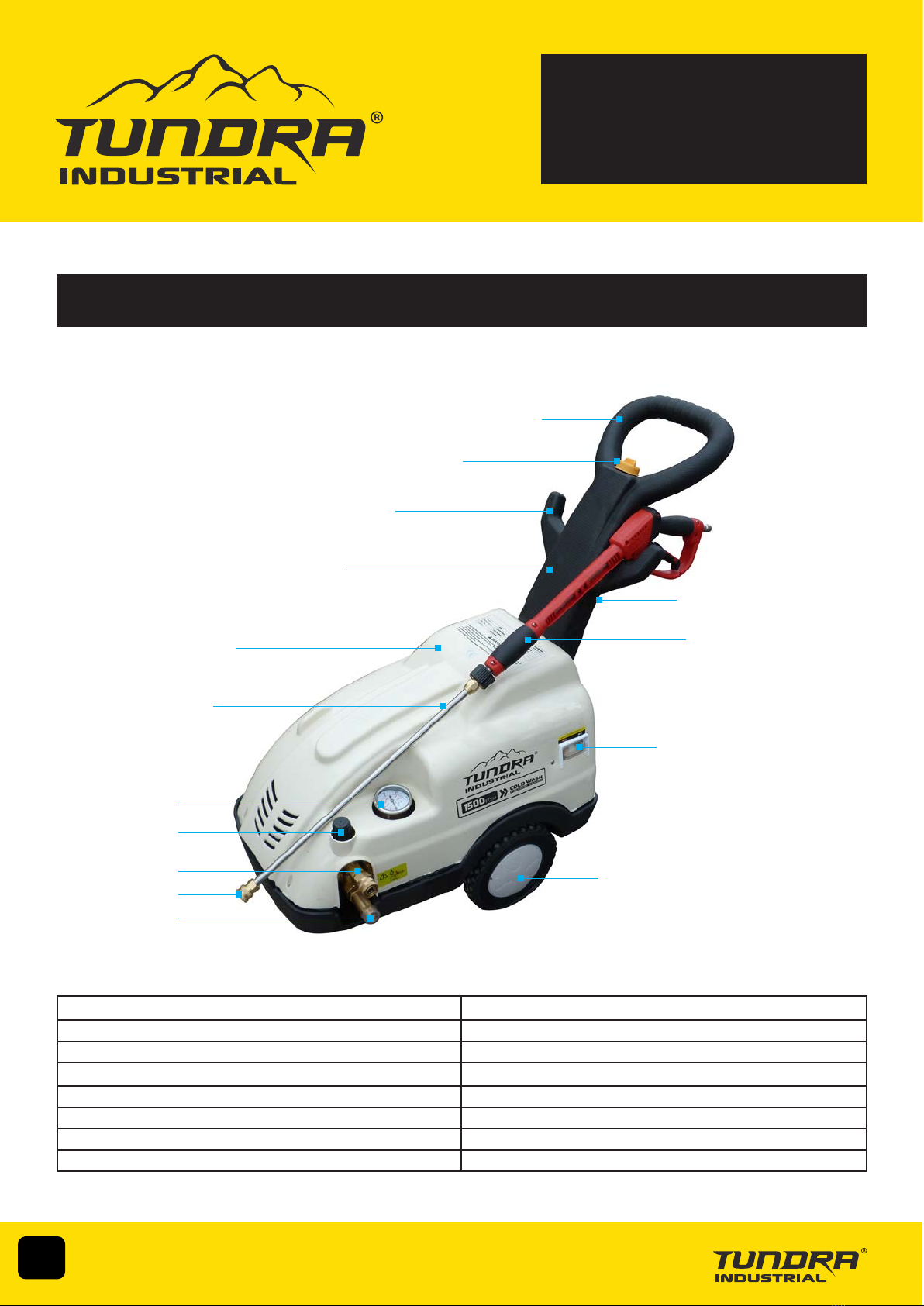
1. Pressure Hose Connection (Outlet) 9. Hose / Gun Retainer
2. Cleaning Nozzle 10. Detergent Filling Cap
3. Water Supply Connection (Inlet) 11. Handle
4. Pressure Regulator 12. Nozzle Holder
5. Pressure Gauge 13. Gun
6. Lance 14. ON (Green) / OFF (Red) Buttons
7. Equipment Housing 15. Wheels
8. Detergent Reservoir
ELECTRICAL SAFETY
Ensure that you check the equipment thoroughly to ensure it is safe and t for purpose before each use. It is important that
you inspect all plugs, sockets, power cables and electrical ttings for wear and damage and repair or replace any defective
components. The risk of electric shock can be minimised by the correct use of the appropriate electrical safety devices.
• We recommend that you t a Residual Current Circuit Breaker (RCCB) in the main distribution
board and that a Residual Current Device (RCD) is used when operating this equipment.
• The Electricity at Work Act 1989 includes legislation that places legal implications on employers
to ensure the safety of electrical devices in the workplace. The regulations dictate that all portable
equipment must be inspected regularly and tested to ensure that it is safe for use. 'Portable
equipment' means any electrical item that can be moved and this is often referred to as Portable
Appliance Testing (PAT). PAT testing should be carried out regularly on this equipment by trained,
authorised personnel, as required by the legislation.
• The Health and Safety at Work Act 1974 states that it is the responsibility of the owner of
electrical appliances to ensure that both the equipment and working environments are maintained to
ensure safe operation at all times.
• Check that all equipment cables are secure, correctly insulated, free from damage, and protected against short circuit and overload before
connecting to the power supply. Do not use worn or damaged cables, plugs, sockets or other ttings.
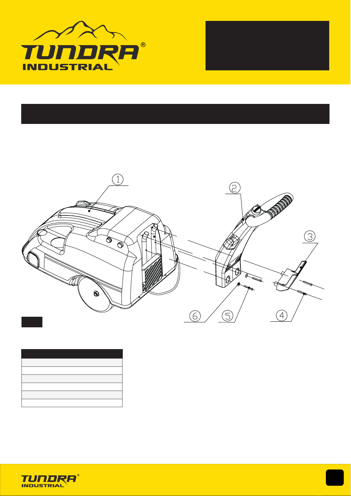
• Ensure that the power supply matches voltage requirements specied on the equipment and that the plug is wired correctly and tted with
the correct fuse (See Fig.3).
• If the electrical fuse blows, ensure it is replaced by an identical type of fuse with the same rating.
• Never pull or manoeuvre this equipment into position using the power cable (move using the handle).
• Ensure the power cable is kept away from heat, oil and sharp edges.
• We recommend that the equipment is connected directly to the power supply without the use of extension leads as the resulting voltage drop
can reduce motor and pump performance.
• All electrical connections should be protected against the water jet and cleaning spray.
• This appliance should always be used with a correctly earthed supply. Contact your electrician for advice if you are unsure.
• Ensure the appliance is disconnected from the power supply before carrying out any maintenance, repairs or adjustments.
SAFETY GUIDELINES
Fig.3
Cable Grip
Neutral
Wire
(Blue)
Earth
Wire
(Brown)
Earth Wire
(Yellow
& Green) 13 Amp
Fuse
Read and ensure that you understand all of the operating instructions, safety precautions and warnings in this Instruction
Manual before operating or maintaining this equipment. Most accidents that result from operation and maintenance are
caused by the failure to observe basic safety rules or precautions. An accident can often be avoided by recognizing
a potentially hazardous situation before it occurs, and by observing appropriate safety procedures. Hazards that
must be avoided to prevent bodily injury or machine damage are identied by warnings on the equipment and in this
Instruction Manual. Never use this equipment or modify it in any way that has not been specically recommended by
the manufacturer. Contact a qualied electrician for advice on any issues relating to electrical safety in your working
environment.