Installation and User Manual D9007050A User Alert Pager System
Press and hold down Reading button for 6 seconds. The “TUNSTALL TELECOM”
message will appear and the vibration alert will activate for several seconds.
To Switch Pager OFF
Repeatedly press Selection button until pager display shows:
Use left and right buttons to choose POWER OFF – text will begin to flash. Press Reading
button to switch pager off
CAUTION – switching pager OFF will mean no pager messages are received.
Receiving a Pager Message
On receipt of a message, the pager will vibrate and the new message will be automatically
displayed on the pager display. Once the message has been read, it can be deleted by
pressing the Selection button twice to enter the following display
Use left and right buttons to choose YES – text will begin to flash. Press Reading button to
delete message
Battery Management
LOW CELL or
If the low battery indicators appear on the pager display the pager battery must be
replaced as soon as possible – the pager will stop working if the battery is too weak.
The battery can be replaced following the procedure below:
1. Switch pager off (see above)
2. Unlock battery cover, slide off the battery compartment cover and remove the old
battery – dispose of the old battery in accordance with local regulations.
3. Put a new alkaline AAA battery into the compartment - ensure correct polarity.
4. Replace the battery compartment cover and lock the battery cover.
5. Switch on the pager (see above)
Service Information
Service of the User Alert Pager system is limited to replacing batteries in Pager
Receivers as necessary (see User Instructions), and replacement of system
components in the event of a fault.
CONTRAST ALERT
MEMORY POWER OFF
DELETE ALL
YES NO
Installation and User Manual D9007050A User Alert Pager System
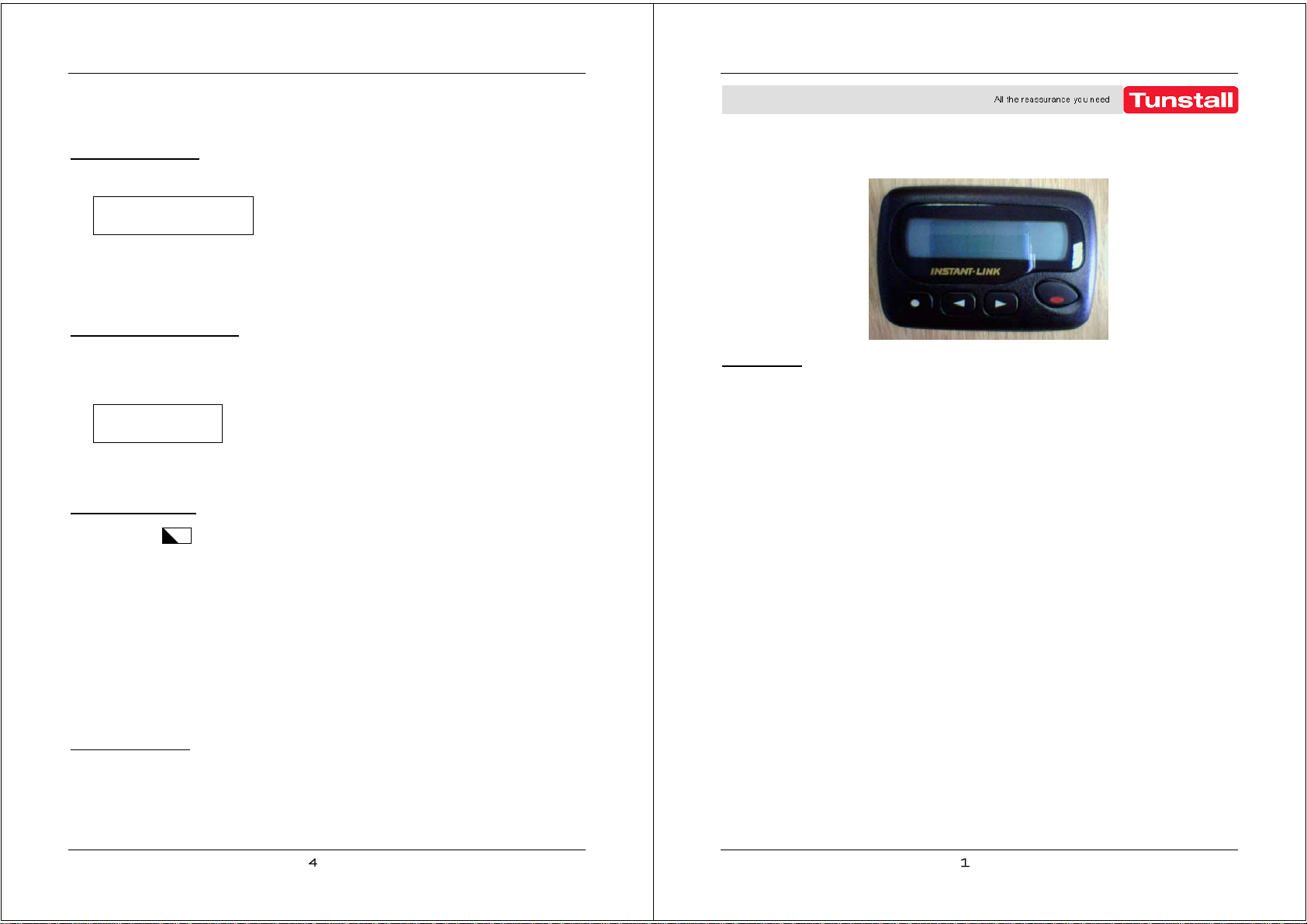
Tunstall User Alert Pager System
Installation and User Manual
Functionality
The Tunstall User Alert Pager System is an optional add-on for Tunstall Haven or
Communicall systems. Its purpose is to provide additional information to hearing impaired
residents of important events within their housing environment, thus ensuring the
requirements of the Disability Discrimination Act are complied with.
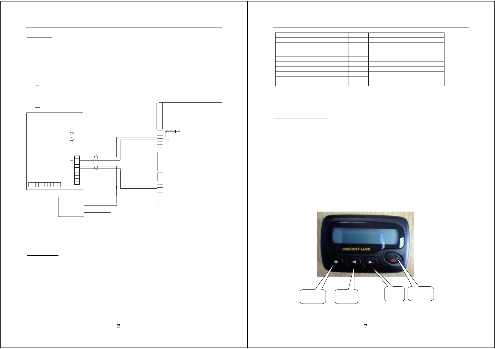
The system comprises a Pager Transmitter (9000/60A), that interfaces to the Haven or
Communicall Control Unit, and a number of Pager Receivers (9000/69A) which are issued
to residents as appropriate.
The Tunstall User Alert Pager System is capable of sending the following text messages
to the resident(s) pager: -
System fire alarm activation - text = FIRE ALARM
Code 3 event (resident’s Tunstall smoke detector) - text = SMOKE DETECTOR
Code 6 event (resident’s Telecare sensors - text = TELECARE SENSOR
Speech module selected for speech - text = Speech Module Selected
Door entry call - text = Door Entry Call
Door open - text = Door Released
The actual messages sent on a given Haven or Communicall system will depend on the
configuration of that system, e.g. door entry messages are dependent on a Haven or
Communicall door entry system being present. The FIRE ALARM message is a group
page and is sent to all pagers, the other messages are resident specific.
On reception of a message, the pager receiver vibrates to attract attention.
IMPORTANT –the Tunstall User Alert Pager should only be used as a secondary means
of alerting residents to safety related events and not relied upon as the primary means of
notification of such events.