Tunstall 77 3410 00 User manual

00 8804 47, 01/21 (Rev. 2.0) - 1 -
© Tunstall GmbH, Orkotten 66, 48291 Telgte, Germany, www.tunstall.de
DE - Installationsanleitung EN - Installation Instructions
Netzgerät 10A, DIN-Schiene,
Bestell-Nr. 77 3410 00
Power supply unit 10A, DIN rail,
Order no. 77 3410 00
Vor Inbetriebnahme lesen!
Bitte lesen Sie diese Warnungen und Hinweise sorgfältig durch, be-
vor Sie das Gerät in Betrieb nehmen. Bewahren Sie die Anleitung
zum Nachlesen auf. Das Gerät darf nur durch fachkundiges und qua-
lifiziertes Personal installiert werden. Bei Funktionsstörungen oder
Beschädigungen schalten Sie sofort die Versorgungsspannung ab
und senden das Gerät zur Überprüfung ins Werk. Das Gerät beinhal-
tet keine Servicebauteile. Die angegebenen Daten dienen allein der
Produktbeschreibung und sind nicht als zugesicherte Eigenschaften
im Rechtssinne aufzufassen. Im Zweifelsfall gilt der englische Text.
Read this first!
Before operating this device, please read this manual thoroughly and
retain this manual for future reference! This device may only be in-
stalled and put into operation by qualified personnel. If damage or
malfunction should occur during operation, immediately turn power
off and send device to the factory for inspection. The device does not
contain serviceable parts. The information presented in this docu-
ment is believed to be accurate and reliable and may change without
notice. For any clarifications the English translation will be used.
WARNUNG! Missachtung nachfolgender Punkte
kann einen elektrischen Schlag, Brände, schwere
Unfälle oder Tod zur Folge haben:
Schalten Sie die Eingangsspannung vor Installations-, Wartungs-
oder Änderungsarbeiten ab und sichern Sie diese gegen unbeab-
sichtigtes Wiedereinschalten.
Führen Sie keine Änderungen oder Reparaturversuche am Gerät
durch. Gerät nicht öffnen!
Verhindern Sie das Eindringen von Fremdkörpern, wie z.B. Büro-
klammern und Metallteilen.
Betreiben Sie das Gerät nicht in feuchter Umgebung oder in ei-
ner Umgebung, bei der mit Betauung oder Kondensation zu
rechnen ist.
Gehäuse nicht während des Betriebes oder kurz nach dem Ab-
schalten berühren. Heiße Oberflächen können Verletzungen
verursachen.
WARNING! Risk of electrical shock, fire, personal
injury, or death:
Turn power off before working on the device. Protect against in-
advertent re-powering.
Do not open, modify or repair the device.
Use caution to prevent any foreign objects from entering the
housing.
Do not use in wet locations or in areas where moisture or con-
densation can be expected.
Do not touch during power-on and immediately after power-off.
Hot surfaces may cause burns.
WARNUNG! Brandgefahr:
Das Netzgerät ist geeignet für Rufanlagen Flamenco, Fla-
mencoSE, EccoLine, NewLine, CONCENTO und VKS 3000.
Das Netzgerät darf in Altsystemen CCS (Krankenhaus, Pflegeheim)
und VKS 2000 (JVA) nicht verwendet werden. Im Fall eines Kurz-
schlusses kann es in diesen Systemen zu einem Brand der Leitungen
kommen.
Wenn das Netzgerät dennoch in einem CCS- oder VKS 2000-System
verwendet werden soll, muss jedes Terminal in jedem Raum wie
unten dargestellt abgesichert werden:
HINWEIS! VKS 2000 Terminals sind zu erkennen an der Typ-Nr.
22.96xx oder 22.98xx auf der Leiterplatte.
WARNING! Risk of fire:
The power supply unit is suitable for Flamenco, Fla-
mencoSE, EccoLine, NewLine, CONCENTO and
VKS 3000 systems.
The power supply unit must not be used in legacy systems CCS
(nurse call system) and VKS 2000 (prison system). In these systems
the cables may burn in case of a short-circuit.
If this power supply needs to be used in CCS or in VKS 2000 system,
each room terminal has to be equipped with a fuse as shown be-
low:
NOTE! VKS 2000 terminals are identified by the type no. 22.96xx or
22.98xx on the printed circuit board.
Produktbeschreibung
Das Netzgerät 10A, DIN-Schiene (77 3410 00) ist ein auf einer DIN-
Schiene montierbares Einphasen-Netzteil für den industriellen Einsatz
und den Einsatz in medizinischen Systemen. Es liefert eine potential-
freie, stabilisierte und galvanisch getrennte SELV/PELV-Ausgangsspan-
nung.
Die Besonderheit dieses Netzteils ist die 2MOPP (two means of patient
protection) Sicherheitszulassung für den medizinischen Gebrauch und
die Erfüllung der erforderlichen EMV-Tests für professionelle Gesund-
heitseinrichtungen und häusliche Gesundheitsversorgung.
Product Description
The 77 3410 00 is a DIN-rail mountable single-phase-input power sup-
ply for industrial use and for use in medical equipment. It provides a
floating, stabilized and galvanically separated SELV/PELV output volt-
age.
The specialty of this power supply is the 2MOPP (two means of patient
protection) safety approval for medical use and the fulfilment of the
required EMC tests for professional healthcare facility and home
healthcare environments.
Anschlüsse
im Terminal
+24V
0V
Stromversorgungsleitung
NYM... vom vorigen Raum
+24V
0V
Stromversorgungsleitung
NYM... zum nächsten Raum
+24V
abgesichert
...
...
...
...
Steck-Schraubklemme mit Sicherungshalter (Best.-Nr. 00 0224 81),
Sicherung 3,15 AT (Best.-Nr. 00 0130 23)
Verbindungsdosenklemme (Best.-Nr. 00 0210 21)
Connecons
in the terminal
+24V
0V
Power supply cable NYM...
from previous room
+24V
0V
Power supply cable NYM...
to next room
+24V
fuse
...
...
...
...
Plug-in screw terminal with fuseholder (order no. 00 0224 81),
fuse 3.15 A, slow blow (order no. 00 0130 23)
Push−wire connector for juncon boxes (order no. 00 0210 21)

00 8804 47, 01/21 (Rev. 2.0) - 2 -
© Tunstall GmbH, Orkotten 66, 48291 Telgte, Germany, www.tunstall.de
Bestimmungsgemäßer Gebrauch
Dieses Gerät ist für den Einbau in ein Gehäuse ausgelegt und ist vorge-
sehen für die Verwendung in medizinischen Systemen.
Verwenden Sie dieses Gerät nicht in Hochfrequenz-Chirurgiegeräten
oder ähnlichen Geräten.
In Anlagen, in denen eine Fehlfunktion oder ein Ausfall dieses Gerätes
zu schweren Verletzungen führen oder Menschenleben gefährden
kann, darf dieses Gerät nur dann verwendet werden, wenn vor Ort
technische und/oder organisatorischeMaßnahmen getroffen werden,
die die Folgen der Fehlfunktion ausgleichen.
Intended Use
This device is designed for installation in an enclosure and is intended
for use in medical equipment.
Do not use this device in HF surgical equipment or similar equipment.
In systems where failure or failure of this equipment may cause seri-
ous injury or endanger human life, this equipment must be used only
if technical and / or organizational measures are taken to correct the
effects of the malfunction.
Funktionsschaltbild Functional Diagram
DE - Installationsanleitung EN - Installation Instructions
Eingangs-
sicherung
Eingangsfilter
Eingangs-
gleichrichter
Einschaltstrom-
begrenzer
PFC-
Konverter Power-
Konverter Ausgangs-
filter
Spannungs-
regler
Tem pe -
ratur-
abschal-
tung
Ausgangs-
leistungs-
manager
Überspan-
nungs-
schutz am
Ausgang
DC-OK
Relais DC-OK
Kontact
DC-OK
LED
Input Fuse
Input Filter
Input Recfier
Inrush Current
Limiter
PFC
Converter Power
Converter Output
Filter
Voltage
Regulator
Temper-
ature
Shut-
down
Output
Power
Manager
Output
Over-
Voltage
Protecon
DC-OK
Relay DC-OK
Contact
DC-OK
LED
Output voltage
Ausgangsstrom
Adjustment range
Output current
Ausgangsspannung
Ausgangscharakterisk / Output characterisc
Einstellbereich Allowed output current at 24V
Zulässiger Ausgangsstrom bei 24V
Umgebungstemperatur
Temperaturbereich / Temperature range
Ambient temperature
15A
24V
12V
0V
3A 6A 9A 12A0A
28V
A: Dauerstrom / Connuous current
B: Unterbrochener Strom / Intermient current
A
B
0A
-25
A: dauerha / connuous
B: kurzzeig /short term (max. 60s)
12A
+250+45+70°C
7,5A
AB
10A
+60

00 8804 47, 01/21 (Rev. 2.0) - 3 -
© Tunstall GmbH, Orkotten 66, 48291 Telgte, Germany, www.tunstall.de
Installationsanleitung
Installieren Sie das Gerät in einem Gehäuse, das vor elektrischen, me-
chanischen und Brandgefahren schützt.
Installieren Sie das Gerät so auf eine DIN-Schiene nach EN 60715, dass
sich die Eingangsklemmen an der Unterseite des Gerätes befinden.
Andere Einbaulagen erfordern eine Reduzierung des Ausgangsstroms.
Verwenden Sie geschirmte oder ungeschirmte Kabel, verdrillte oder
nicht verdrillte Kabel beliebiger Länge. Stellen Sie sicher, dass die Ver-
kabelung korrekt ist, indem Sie alle lokalen und nationalen Vorschrif-
ten befolgen. Verwenden Sie geeignete Kupferkabel, die für eine
Mindestbetriebstemperatur von 90°C bei Umgebungstemperaturen
zwischen +45°C und +60°C und 105°C bei Umgebungstemperaturen
bis +70°C ausgelegt sind. Achten Sie darauf, dass alle Einzeldrähte ei-
ner Litze in den Klemmenanschluss gelangen.
Das Gerät ist für Bereiche des Verschmutzungsgrades 2 in kontrollier-
ten Umgebungen ausgelegt. Kondensation oder Frostbildung sind
nicht erlaubt.
Das Gehäuse des Gerätes bietet eine Schutzart von IP20. Das Gehäuse
bietet keinen Schutz vor verschütteten Flüssigkeiten.
Die Isolierung des Gerätes ist so ausgelegt, dass sie Stoßspannungen
der Überspannungskategorie III nach IEC 60664-1 widersteht.
Das Gerät ist als Gerät der "Schutzklasse I" nach IEC 61140 ausgeführt.
Nicht ohne ordnungsgemäßen PE (Protective Earth)-Anschluss ver-
wenden.
Das Netzgerät kann mit den Netzformen TN, TT oder IT versorgt wer-
den. Die Dauerspannung zwischen der Eingangsklemme und dem PE-
Potential darf 300Vac nicht überschreiten.
Der Eingang kann auch aus Batterien oder ähnlichen Gleichstromquel-
len gespeist werden. Die Dauerspannung zwischen der Versorgungs-
spannung und dem PE/Massepotential darf 375Vdc nicht
überschreiten.
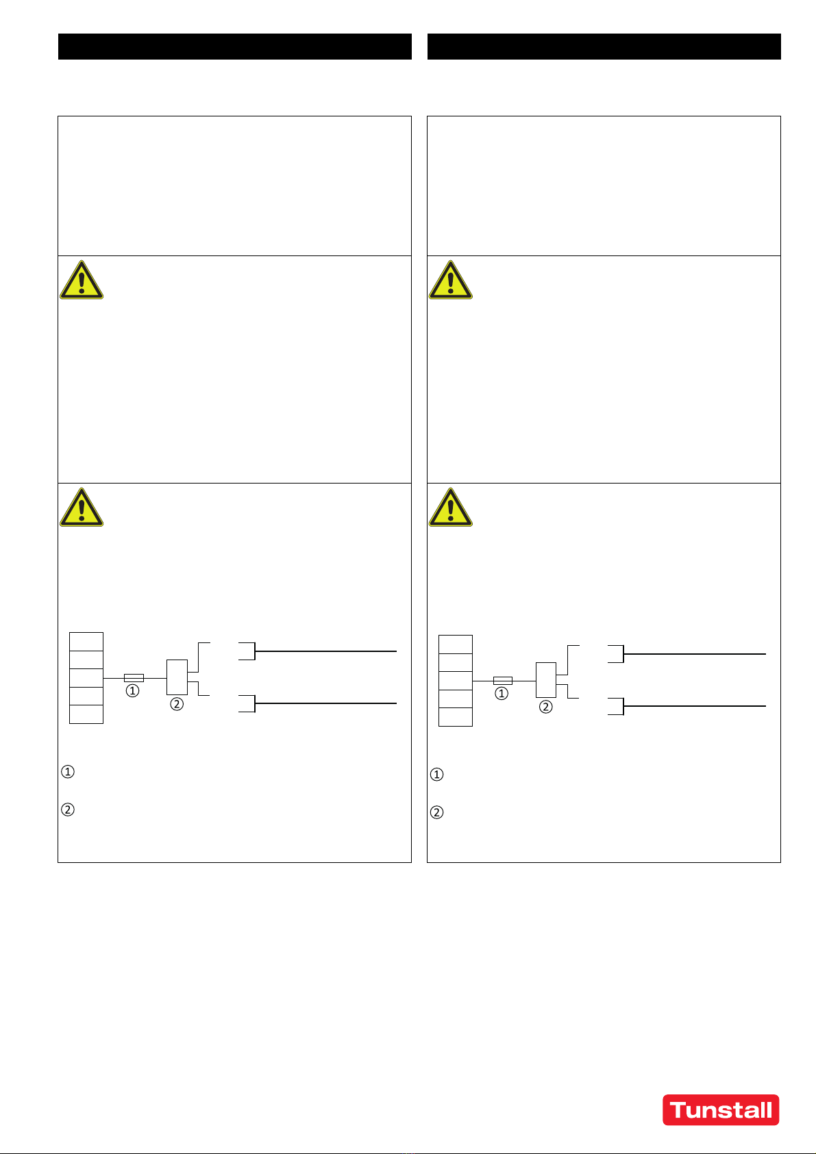
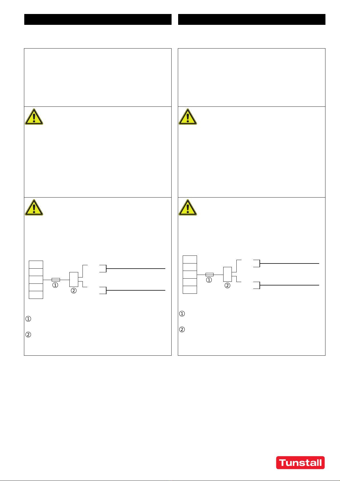
An der Eingangsseite des Gerätes muss eine Trennvorrichtung vorge-
sehen werden.
Das Gerät ist für Konvektionskühlung ausgelegt und benötigt keinen
externen Lüfter. Behindern Sie die Luftzirkulation nicht, und verde-
cken Sie die Lüftungsgitter nicht!
Das Gerät ist für Höhen bis zu 3000m ausgelegt.
Halten Sie die folgenden minimalen Einbauabstände ein: 40mm oben,
20mm unten, 5mm auf der linken und rechten Seite. Erhöhen Sie die-
sen Abstand von 5mm auf 15mm, wenn das benachbarte Gerät eine
Wärmequelle ist. Wenn das Gerät dauerhaft mit weniger als 50% be-
lastet wird, können die 5mm auf Null reduziert werden.
Das Gerät ist für Abzweigstromkreise bis 32A (IEC) und 30A (UL) ohne
zusätzliche Schutzeinrichtung ausgelegt, getestet und zugelassen.
Wenn eine externe Sicherung verwendet wird, verwenden Sie keine
Schutzschalter, die kleiner als 6A B- oder C-Kennlinie sind, um ein stö-
rendes Auslösen des Schutzschalters zu vermeiden.
Die maximale Umgebungslufttemperatur beträgt +70°C. Die Betriebs-
temperatur ist dieselbe wie die Umgebungs- oder Umgebungslufttem-
peratur und ist definiert 2 cm unter dem Gerät.
Das Gerät ist für den Betrieb in Bereichen zwischen 5% und 95% rela-
tiver Luftfeuchtigkeit ausgelegt.
Tragbare Hochfrequenz-Kommunikationsgeräte sollten nicht näher als
30 cm zu dem Netzgerät oder den Anschlusskabeln des Netzgerätes
verwendet werden.
WARNUNG: Die Verwendung dieses Geräts in der Nähe von oder über-
einandergestapelt mit anderen Geräten sollte vermieden werden, da
dies zu unsachgemäßem Betrieb führen kann. Wenn eine solche Ver-
wendung erforderlich ist, sollten dieses und die anderen Geräte beob-
achtet werden, um sicherzustellen, dass sie ordnungsgemäß
funktionieren.
Installation Instructions
Install device in an enclosure providing protection against electrical,
mechanical and fire hazards.
Install the device onto a DIN-rail according to EN 60715 with the input
terminals on the bottom of the device. Other mounting orientations
require a reduction in output current.
Use shielded or unshielded cables, twisted or untwisted cables of any
length. Make sure that the wiring is correct by following all local and
national codes. Use appropriate copper cables that are designed for a
minimum operating temperature of 90°C for ambient temperatures
between +45°C and +60°C and 105°C for ambient temperatures up to
+70°C. Ensure that all strands of a stranded wire enter the terminal
connection.
The device is designed for pollution degree 2 areas in controlled envi-
ronments. No condensation or frost is allowed.
The enclosure of the device provides a degree of protection of IP20.
The enclosure does not provide protection against spilled liquids.
The isolation of the device is designed to withstand impulse voltages
of overvoltage category III according to IEC 60664-1.
The device is designed as “Class of Protection I” equipment according
to IEC 61140. Do not use without a proper PE (Protective Earth) con-
nection.
The device is suitable to be supplied from TN, TT or IT mains networks.
The continuous voltage between the input terminal and the PE poten-
tial must not exceed 300Vac.
The input can also be powered from batteries or similar DC sources.
The continuous voltage between the supply voltage and the PE/
ground potential must not exceed 375Vdc.
A disconnecting means shall be provided for the input of the device.
The device is designed for convection cooling and does not require an
external fan. Do not obstruct airflow and do not cover ventilation grid!
The device is designed for altitudes up to 3000m (9840ft).
Keep the following minimum installation clearances: 40mm on top,
20mm on the bottom, 5mm left and right side. Increase the 5mm to
15mm in case the adjacent device is a heat source. When the device is
permanently loaded with less than 50%, the 5mm can be reduced to
zero.
The device is designed, tested and approved for branch circuits up to
32A (IEC) and 30A (UL) without additional protection device. If an ex-
ternal fuse is utilized, do not use circuit breakers smaller than 6A B- or
C-Characteristic to avoid a nuisance tripping of the circuit breaker.
The maximum surrounding air temperature is +70°C (+158°F). The op-
erational temperature is the same as the ambient or surrounding air
temperature and is defined 2cm below the device.
The device is designed to operate in areas between 5% and 95% rela-
tive humidity.
Portable RF communication equipment should be used no closer than
30cm (12 inch) to the power supply or the power supply connection
cables.
WARNING: Use of this equipment adjacent to or stacked with other
equipment should be avoided because it could result in improper op-
eration. If such use is necessary, this equipment and the other equip-
ment should be observed to verify that they are operating normally.
DE - Installationsanleitung EN - Installation Instructions

00 8804 47, 01/21 (Rev. 2.0) - 4 -
© Tunstall GmbH, Orkotten 66, 48291 Telgte, Germany, www.tunstall.de
Funktionsbeschreibung
Der Ausgang ist elektronisch gegen Leerlauf, Überlast und Kurzschluss
geschützt und kann jede Art von Lasten versorgen, einschließlich un-
begrenzter induktiver und kapazitiver Lasten. Wenn Kondensatoren
mit einer Kapazität >1,5F angeschlossen sind, könnte das Gerät den
Kondensator in einem intermittierenden Modus laden.
Legen Sie keine Rückspannungen vom Verbraucher an die Ausgangs-
klemmen größer als 35V an.
Die Ausgangsspannung kann mit einem kleinen Schlitz-Schraubendre-
her an der Vorderseite eingestellt werden.
Die grüne DC-OK-LED meldet eine Ausgangsspannung über 90% der
eingestellten Spannung eines laufenden Gerätes.
Das DC-OK-Relais überwacht die Ausgangsspannung und der Kontakt
ist geschlossen, wenn die DC-OK-LED leuchtet. Schaltleistungen:
60Vdc 0,3A, 30Vdc 1A, 30Vac 0,5A für ohmsche Lasten.
Das Gerät ist mit einem Übertemperaturschutz ausgestattet. Im Fall
einer hohen Temperatur schaltet sich der Ausgang ab und startet nach
dem Abkühlen automatisch wieder.
Bei starken Überlasten (wenn die Ausgangsspannung unter 13V fällt)
liefert das Gerät einen kontinuierlichen Ausgangsstrom für 2s. Danach
wird der Ausgang für 18s abgeschaltet, bevor automatisch ein neuer
Startversuch durchgeführt wird. Dieser Zyklus wird solange wieder-
holt, wie die Überlast besteht.
Schließen Sie die Ausgänge von Geräten nicht in Parallelschaltung für
höhere Ausgangsströme an.
Schließen Sie die Ausgänge von Geräte nicht in Reihenschaltung für
höhere Ausgangsspannungen an.
Bei einem internen Fehler begrenzt eine redundante Schaltung die
maximale Ausgangsspannung auf 32V. Der Ausgang wird abgeschaltet
und versucht automatisch, neu zu starten.
Functional Description
The output is electronically protected against no-load, overload and
short circuit and can supply any kind of loads, including unlimited in-
ductive and capacitive loads. If capacitors with a capacitance >1.5F are
connected, the unit might charge the capacitor in an intermittent
mode.
Do not apply return voltages from the load to the output higher than
35V.
The output voltage can be adjusted with a small flat-blade screwdriver
on the front of the unit.
The green DC OK LED reports an output voltage above 90% of the ad-
justed voltage of a running device.
The DC OK relay monitors the output voltage and the contact is closed
when the DC OK LED is on. Contact ratings: 60Vdc 0.3A, 30Vdc 1A,
30Vac 0.5A for resistive loads.
The device is equipped with an over-temperature protection. In case
of a high temperature, the output shuts down and starts automatically
again after cooling off.
At heavy overloads (when output voltage falls below 13V), the device
delivers continuous output current for 2s. After this, the output is
switched off for 18s before a new start attempt is automatically per-
formed. This cycle is repeated as long as the overload exists.
Do not connect outputs of devices in a parallel connection for higher
output currents.
Do not connect outputs of devices in a series connection for higher
output voltages.
In case of an internal defect, a redundant circuit limits the maximum
output voltage to 32V. The output shuts down and automatically at-
tempts to restart.
Technische Daten
Alle Werte sind typische Werte, angegeben für 230Vac 50Hz Eingangs-
spannung, 24V 10A Ausgangslast, 25°C Umgebungstemperatur und
nach einer Aufwärmzeit von 5 Minuten, sofern nicht anders angege-
ben.
Technical data
All values are typical figures specified at 230Vac 50Hz input voltage,
24V 10A output load, 25°C ambient temperature and after a 5 minutes
run-in time unless otherwise noted.
DE - Installationsanleitung EN - Installation Instructions
Ausgangsspannung DC 24V Nominal
Einstellbereich 24 – 28Vdc Werkseinstellung 24,1V
Ausgangsstrom
kontinuierlich 12,0 – 10,3A Umgebung unter +45°C
10,0 – 8,6A Bei +60°C Umgebung
7,5 – 6,5A Bei +60°C Umgebung
Lineare Abnahme zwischen +45°C und
+70°C
Eingangsspannung AC AC 100 – 240V -15% / +10%
Netzfrequenz 50 – 60Hz ±6%
Eingangsstrom AC 2,15 / 1,13A Bei 120 / 230Vac
Leistungsfaktor 0,99 / 0,97 Bei 120 / 230Vac
Eingangsspannung DC DC 110 – 150V ±20%
Eingangsstrom DC 2,35A Bei 110Vdc
Eingangseinschaltstrom 6 / 9A Spitze Bei 40°C, 120 / 230Vac
Wirkungsgrad 93,6 / 95,2% Bei 120 / 230Vac
Leistungsverluste 16,4 / 12,1W Bei 120 / 230Vac
Überbrückungszeit 37ms
Temperaturbereich -25 bis +70°C
Max. Drahtquerschnitt
(Litze) 4mm² Klemmen Eingang/Aus-
gang
American Wire Gauge AWG 20-10 Klemmen Eingang/Aus-
gang
Max. Drahtdurchmesser 2,8mm Klemmen Eingang/Aus-
gang
Abisolierlänge 10mm Klemmen Eingang/Aus-
gang
Max. Drahtquerschnitt
(Litze) 1,5mm² DC-OK-Klemmen
American Wire Gauge AWG 24–16 DC-OK-Klemmen
Max. Drahtdurchmesser 1,6 mm DC-OK-Klemmen
Abisolierlänge 7mm DC-OK-Klemmen
Abmessungen (HxBxT) 124x 39x117
mm Ohne DIN-Schiene
Gewicht 620g
Output voltage DC 24V Nominal
Adjustment range 24 – 28Vdc Factory setting 24.1V
Output current
continuous 12.0 – 10.3A Below +45°C ambient
10.0 – 8.6A At +60°C ambient
7.5 – 6.5A At +70°C ambient
Derate linearly between +45°C and +70°C
Input voltage AC AC 100 – 240V -15% / +10%
Mains frequency 50 – 60Hz ±6%
Input current AC 2.15 / 1.13A At 120 / 230Vac
Power factor 0.99 / 0.97 At 120 / 230Vac
Input voltage DC DC 110 – 150V ±20%
Input current DC 2.35A At 110Vdc
Input inrush current 6 / 9A pk At 40°C, 120 / 230Vac
Efficiency 93.6 / 95.2% At 120 / 230Vac
Power losses 16.4 / 12.1W At 120 / 230Vac
Hold-up time 37ms
Temperature range -25 to +70°C
Max. wire size
(litz wire) 4mm² Power terminals
Wire size AWG AWG 20-10 Power terminals
Max. wire diameter 2.8mm Power terminals
Wire stripping length 10mm / 0.4inch Power terminals
Max. wire size
(litz wire) 1.5mm² DC-OK terminals
Wire size AWG AWG 24–16 DC-OK terminals
Max. wire diameter 1.6 mm DC-OK terminals
Wire stripping length 7mm / 0.28inch DC-OK terminals
Size (wxhxd) 39x124x117mm Without DIN-rail
Weight 620g / 1.37lb

00 8804 47, 01/21 (Rev. 2.0) - 5 -
© Tunstall GmbH, Orkotten 66, 48291 Telgte, Germany, www.tunstall.de
FR - Mode d'installation EN - Installation Instructions
Bloc d’alimentation 10A, rail DIN,
référence 77 3410 00
Power supply unit 10A, DIN rail,
Order no. 77 3410 00
A lire avant mise sous tension !
Veuillez lire ces instructions de montage et d'entretien avant de
mettre l'alimentation sous tension. Conservez ce manuel qui vous
sera toujours utile. Cette alimentation ne doit être installée que par
du personnel qualifié et compétent. En cas de dommage ou dysfonc-
tionnement, coupez immédiatement l’alimentation et retournez l’ap-
pareil à l’usine pour vérification ! L’alimentation ne contient pas de
pièces échangeables Les données indiquées dans ce document
servent uniquement à donner une description du produit et n'ont au-
cune valeur juridique. En cas de divergences, le texte anglais fait foi.
Read this first!
Before operating this device, please read this manual thoroughly and
retain this manual for future reference! This device may only be in-
stalled and put into operation by qualified personnel. If damage or
malfunction should occur during operation, immediately turn power
off and send device to the factory for inspection. The device does not
contain serviceable parts. The information presented in this docu-
ment is believed to be accurate and reliable and may change without
notice. For any clarifications the English translation will be used.
AVERTISSEMENT ! Prendre en compte les points sui-
vants, afin d'éviter toute détérioration électrique,
risque d’incendie, dommage corporels ou blessures
mortelles :
Mettre l’alimentation hors tension avant toute intervention sur
celle-ci et s'assurer qu'il n'y a pas risque de redémarrage.
Ne pas ouvrir, modifier ou réparer l'alimentation.
Veiller à ce qu'aucun objet ne rentre en contact avec l'intérieur de
l'alimentation (trombones, pièces métalliques).
Ne pas faire fonctionner l'appareil dans un environnement hu-
mide ou dans un environnement où il peut y avoir de la conden-
sation.
Ne pas toucher le carter pendant le fonctionnement ou directe-
ment après la mise hors tension. Surface chaude risquant d’en-
traîner des blessures.
WARNING! Risk of electrical shock, fire, personal
injury, or death:
Turn power off before working on the device. Protect against in-
advertent re-powering.
Do not open, modify or repair the device.
Use caution to prevent any foreign objects from entering the
housing.
Do not use in wet locations or in areas where moisture or conden-
sation can be expected.
Do not touch during power-on and immediately after power-off.
Hot surfaces may cause burns.
AVERTISSEMENT ! Risque d’incendie :
Le bloc d’alimentation est prévu pour des systèmes
Flamenco, FlamencoSE, EccoLine, NewLine, CONCENTO et
VKS 3000.
Le bloc d'alimentation ne doit pas être utilisé dans les anciens sys-
tèmes CCS (système d'appel malade) et VKS 2000 (système de pri-
son).
Si le bloc d’alimentation doit être utilisé quand même dans un sys-
tème CCS ou VKS 2000, chaque terminal dans chaque chambre doit
être équipé d’un fusible comme montré ci-dessous :
REMARQUE ! Les terminaux VKS 2000 peuvent être identifiés par le
numéro de type 22.96xx ou 22.98xx sur le circuit imprimé.
WARNING! Risk of fire:
The power supply unit is suitable for Flamenco, Fla-
mencoSE, EccoLine, NewLine, CONCENTO and
VKS 3000 systems.
The power supply unit must not be used in legacy systems CCS
(nurse call system) and VKS 2000 (prison system). In these systems
the cables may burn in case of a short-circuit.
If this power supply needs to be used in CCS or in VKS 2000 system,
each room terminal has to be equipped with a fuse as shown below:
NOTE! VKS 2000 terminals are identified by the type no. 22.96xx or
22.98xx on the printed circuit board.
Description du produit
Le 77 3410 00 est un bloc d'alimentation monophasé qui peut être
monté sur rail DIN pour une utilisation industrielle et médicale.
La particularité de ce bloc d’alimentation est l’approbation de sécurité
2MOPP (deux moyens de protection pour les patients) pour une utilisa-
tion médicale et la réalisation des tests CEM requis pour les établisse-
ments de santé professionnels et les soins de santé à domicile.
Product Description
The 77 3410 00 is a DIN-rail mountable single-phase-input power supply
for industrial use and for use in medical equipment. It provides a float-
ing, stabilized and galvanically separated SELV/PELV output voltage.
The specialty of this power supply is the 2MOPP (two means of patient
protection) safety approval for medical use and the fulfilment of the re-
quired EMC tests for professional healthcare facility and home health-
care environments.
Connexions
dans le terminal
+24V
0V
Câble d'alimentaon NYM...
de la chambre précédente
+24V
0V
Câble d'alimentaon NYM...
vers la chambre suivante
+24V
fusible
...
...
...
...
Bornier avec support de fusible (référence 00 0224 81),
fusible 3,15 AT (référence 00 0130 23)
Borne de dérivaon (référence 00 0210 21)
Connecons
in the terminal
+24V
0V
Power supply cable NYM...
from previous room
+24V
0V
Power supply cable NYM...
to next room
+24V
fuse
...
...
...
...
Plug-in screw terminal with fuseholder (order no. 00 0224 81),
fuse 3.15 A, slow blow (order no. 00 0130 23)
Push−wire connector for juncon boxes (order no. 00 0210 21)

00 8804 47, 01/21 (Rev. 2.0) - 6 -
© Tunstall GmbH, Orkotten 66, 48291 Telgte, Germany, www.tunstall.de
Utilisation conforme
Cet appareil est conçu pour être installé dans un boîtier et est destiné à
être utilisé dans un équipement médical.
Ne pas utiliser cet appareil dans des appareils chirurgicaux à haute fré-
quence ou des appareils similaires.
Dans les systèmes où un dysfonctionnement ou une panne de cet appa-
reil pourrait causer des blessures graves ou un risque de décès, cet ap-
pareil ne doit être utilisé que si des mesures techniques et/ou
organisationnelles sont prises pour compenser les effets du dysfonc-
tionnement.
Intended Use
This device is designed for installation in an enclosure and is intended
for use in medical equipment.
Do not use this device in HF surgical equipment or similar apertures.
In systems where failure or failure of this equipment may cause serious
injury or endanger human life, this equipment must be used only if
technical and / or organizational measures are taken to correct the ef-
fects of the malfunction.
Schéma fonctionnel Functional Diagram
FR - Mode d'installation EN - Installation Instructions
Fusible d‘entrée
Filtre d‘entrée
Redresseur
d‘entrée
Limiteur de
courant
d‘entrée
Conversseur
PFC
Filtre de
sore
Régulateur
de tension
Arrêt
de
tempéra-
ture
Gesonnaire
de puissance
de sore
Protecon
contre
surtensions
de sore
Relais
DC-OK Contact
DC-OK
LED
DC-OK
Conversseur
Power
Input Fuse
Input Filter
Input Recfier
Inrush Current
Limiter
PFC
Converter Power
Converter Output
Filter
Voltage
Regulator
Temper-
ature
Shut-
down
Output
Power
Manager
Output
Over-
Voltage
Protecon
DC-OK
Relay DC-OK
Contact
DC-OK
LED
Output voltage
Courant de sore
Adjustment range
Output current
Tension de sore
Caractérisque de sore / Output characterisc
Plage de réglage Allowed output current at 24V
Courant de sore admissible à 24V
Température ambiante
Plage des températures / Temperature range
Ambient temperature
15A
24V
12V
0V
3A 6A 9A 12A0A
28V
A: Courant permanent / Connuous current
B: Courant intermient / Intermient current
A
B
0A
-25
A: permanent / connuous
B: courte durée /short term (max. 60s)
12A
+250 +45 +70°C
7,5A
AB
10A
+60

00 8804 47, 01/21 (Rev. 2.0) - 7 -
© Tunstall GmbH, Orkotten 66, 48291 Telgte, Germany, www.tunstall.de
Instruction d’installation
Installer l'appareil dans un boîtier offrant une protection contre les
risques électriques, mécaniques et d'incendie.
Monter l'appareil sur un rail DIN selon EN 60715 de telle sorte que les
bornes d'entrée se trouvent sous l'appareil. D'autres orientations de
montage nécessitent une réduction du courant de sortie.
Utilisez des câbles blindés ou non blindés, torsadés ou non torsadés de
toute longueur. Assurez-vous que le câblage est correct en suivant tous
les codes locaux et nationaux. Utiliser des câbles en cuivre appropriés,
conçus pour une température de fonctionnement minimale de 90°C
pour des températures ambiantes comprises entre +45°C et +60°C et
105°C pour des températures ambiantes jusqu'à +70°C. S'assurer que
tous les fils d'un toron entrent dans le bornier.
L'appareil est conçu pour les zones de degré de pollution 2 dans des en-
vironnements contrôlés. Il ne faut aucune condensation ou gelée.
Le boîtier de l'appareil offre un indice de protection IP20. Le boîtier
n'offre aucune protection contre les liquides renversés.
L'isolation de l'appareil est conçue pour résister aux surtensions de ca-
tégorie III selon CEI 60664-1.
L'appareil est conçu comme un appareil de "classe de protection I" se-
lon CEI 61140. Ne l'utilisez pas sans une connexion PE appropriée (fil de
protection).
L'appareil peut être alimenté par les réseaux TN, TT ou IT. La tension
continue entre la borne d'entrée et le potentiel PE ne doit pas dépasser
300Vac.
L'entrée peut également être alimentée par des piles ou des sources de
courant continu similaires. La tension continue entre la tension d'ali-
mentation et le potentiel PE/terre ne doit pas dépasser 375Vdc.
Un dispositif de déconnexion doit être prévu à l'entrée de l'appareil.
L'appareil est conçu pour le refroidissement par convection et ne né-
cessite pas de ventilateur externe. Ne pas obstruer le flux d'air et ne pas
couvrir la grille de ventilation !
L'appareil est conçu pour des altitudes allant jusqu'à 3000m.
Respectez les distances de montage minimales suivantes : 40mm en
haut, 20mm en bas, 5mm à gauche et à droite. Augmentez cette dis-
tance de 5mm à 15mm si l'appareil adjacent est une source de chaleur.
Si l'appareil est chargé en permanence avec moins de 50%, les 5mm
peuvent être réduits à zéro
L'appareil est conçu, testé et approuvé pour des circuits de dérivation
jusqu'à 32A (IEC) et 30A (UL) sans dispositif de protection supplémen-
taire. Si un fusible externe est utilisé, n'utilisez pas de disjoncteurs de
moins de 6A de caractéristique B ou C pour éviter un déclenchement in-
tempestif du disjoncteur
La température maximale de l'air ambiant est de +70°C. La température
de fonctionnement est la même que la température ambiante ou la
température de l'air ambiant et est définie à 2 cm sous l'appareil.
L'appareil est conçu pour fonctionner dans des zones entre 5% et 95%
d'humidité relative.
Les équipements de communication RF portables ne doivent pas être
utilisés à moins de 30 cm du bloc d'alimentation ou des câbles de rac-
cordement du bloc d'alimentation.
AVERTISSEMENT : L'utilisation de cet équipement à proximité ou empi-
lé avec d'autres équipements doit être évitée car cela pourrait entraî-
ner un mauvais fonctionnement. Si une telle utilisation est nécessaire,
cet appareil et les autres équipements doivent être observés pour véri-
fier qu'ils fonctionnent normalement.
Installation Instructions
Install device in an enclosure providing protection against electrical,
mechanical and fire hazards.
Install the device onto a DIN-rail according to EN 60715 with the input
terminals on the bottom of the device. Other mounting orientations re-
quire a reduction in output current.
Use shielded or unshielded cables, twisted or untwisted cables of any
length. Make sure that the wiring is correct by following all local and na-
tional codes. Use appropriate copper cables that are designed for a
minimum operating temperature of 90°C for ambient temperatures be-
tween +45°C and +60°C and 105°C for ambient temperatures up to
+70°C. Ensure that all strands of a stranded wire enter the terminal con-
nection.
The device is designed for pollution degree 2 areas in controlled envi-
ronments. No condensation or frost is allowed.
The enclosure of the device provides a degree of protection of IP20. The
enclosure does not provide protection against spilled liquids.
The isolation of the device is designed to withstand impulse voltages of
overvoltage category III according to IEC 60664-1.
The device is designed as “Class of Protection I” equipment according
to IEC 61140. Do not use without a proper PE (Protective Earth) connec-
tion.
The device is suitable to be supplied from TN, TT or IT mains networks.
The continuous voltage between the input terminal and the PE poten-
tial must not exceed 300Vac.
The input can also be powered from batteries or similar DC sources. The
continuous voltage between the supply voltage and the PE/ground po-
tential must not exceed 375Vdc.
A disconnecting means shall be provided for the input of the device.
The device is designed for convection cooling and does not require an
external fan. Do not obstruct airflow and do not cover ventilation grid!
The device is designed for altitudes up to 3000m (9840ft).
Keep the following minimum installation clearances: 40mm on top,
20mm on the bottom, 5mm left and right side. Increase the 5mm to
15mm in case the adjacent device is a heat source. When the device is
permanently loaded with less than 50%, the 5mm can be reduced to ze-
ro.
The device is designed, tested and approved for branch circuits up to
32A (IEC) and 30A (UL) without additional protection device. If an exter-
nal fuse is utilized, do not use circuit breakers smaller than 6A B- or C-
Characteristic to avoid a nuisance tripping of the circuit breaker.
The maximum surrounding air temperature is +70°C (+158°F). The op-
erational temperature is the same as the ambient or surrounding air
temperature and is defined 2cm below the device.
The device is designed to operate in areas between 5% and 95% relative
humidity.
Portable RF communication equipment should be used no closer than
30cm (12 inch) to the power supply or the power supply connection ca-
bles.
WARNING: Use of this equipment adjacent to or stacked with other
equipment should be avoided because it could result in improper oper-
ation. If such use is necessary, this equipment and the other equipment
should be observed to verify that they are operating normally.
FR - Mode d'installation EN - Installation Instructions

00 8804 47, 01/21 (Rev. 2.0) - 8 -
© Tunstall GmbH, Orkotten 66, 48291 Telgte, Germany, www.tunstall.de
Description fonctionnelle
La sortie est protégée électroniquement contre les surcharges et les
courts-circuits et peut alimenter tout type de charge, y compris des
charges inductives et capacitives illimitées. Si des condensateurs d'une
capacité >1,5F sont connectés, l'appareil peut charger le condensateur
en mode intermittent.
Ne pas appliquer de tensions de retour de la charge aux bornes de sor-
tie supérieures à 35V.
La tension de sortie peut être réglée à l'aide d'un petit tournevis plat à
l'avant de l'appareil.
La LED verte DC-OK indique une tension de sortie supérieure à 90% de
la tension réglée d'un appareil en fonctionnement.
Le relais DC-OK surveille la tension de sortie et le contact est fermé
lorsque la LED DC-OK est allumée. Pouvoir de coupure : 60Vdc 0,3A,
30Vdc 1A, 30Vac 0,5A f pour charges résistives.
L'appareil est équipé d'une protection contre les surchauffes. En cas de
température élevée, la sortie s'arrête et redémarre automatiquement
après refroidissement.
En cas de fortes surcharges (lorsque la tension de sortie tombe en des-
sous de 13V), l'appareil fourni un courant de sortie continu pendant 2s.
Ensuite, la sortie est désactivée pendant 18 secondes avant qu'une
nouvelle tentative de démarrage ne soit effectuée automatiquement.
Ce cycle est répété aussi longtemps que la surcharge existe.
Ne connectez pas les sorties des appareils en parallèle pour des cou-
rants de sortie plus élevés.
Ne connectez pas les sorties des appareils en série pour des tensions de
sortie plus élevées.
En cas de défaut interne, un circuit redondant limite la tension de sortie
maximale à 32V. La sortie s'arrête et tente automatiquement de redé-
marrer.
Functional Description
The output is electronically protected against no-load, overload and
short circuit and can supply any kind of loads, including unlimited induc-
tive and capacitive loads. If capacitors with a capacitance >1.5F are con-
nected, the unit might charge the capacitor in an intermittent mode.
Do not apply return voltages from the load to the output higher than
35V.
The output voltage can be adjusted with a small flat-blade screwdriver
on the front of the unit.
The green DC OK LED reports an output voltage above 90% of the ad-
justed voltage of a running device.
The DC OK relay monitors the output voltage and the contact is closed
when the DC OK LED is on. Contact ratings: 60Vdc 0.3A, 30Vdc 1A,
30Vac 0.5A for resistive loads.
The device is equipped with an over-temperature protection. In case of
a high temperature, the output shuts down and starts automatically
again after cooling off.
At heavy overloads (when output voltage falls below 13V), the device
delivers continuous output current for 2s. After this, the output is
switched off for 18s before a new start attempt is automatically per-
formed. This cycle is repeated as long as the overload exists.
Do not connect outputs of devices in a parallel connection for higher
output currents.
Do not connect outputs of devices in a series connection for higher out-
put voltages.
In case of an internal defect, a redundant circuit limits the maximum
output voltage to 32V. The output shuts down and automatically at-
tempts to restart.
Données techniques
Toutes les valeurs sont des valeurs typiques spécifiées pour une tension
d'entrée de 230Vac 50Hz, une charge de sortie de 24V 10A, une tempé-
rature ambiante de 25°C et après un temps de rodage de 5 minutes sauf
indication contraire.
.
Technical data
All values are typical figures specified at 230Vac 50Hz input voltage, 24V
10A output load, 25°C ambient temperature and after a 5 minutes run-
in time unless otherwise noted.
FR - Mode d'installation EN - Installation Instructions
Tension de sortie DC 24V Nominale
Plage de réglage 24 – 28Vdc Réglage usine 24,1V
Courant de sortie
continu 12,0 – 10,3A T. ambiante inférieure à
+45°C
10,0 – 8,6A à t. ambiante de +60°C
7,5 – 6,5A à t. ambiante de +70°C
Diminution linéaire entre +45°C et +70°C
Tension d'entrée AC AC 100 – 240V -15% / +10%
Fréquence du réseau 50 – 60Hz ±6%
Courant d’entrée AC 2.15 / 1.13A À 120 / 230Vac
Facteur de puissance 0,99 / 0,97 À 120 / 230Vac
Tension d'entrée DC DC 110 – 150V ±20%
Courant d’entrée DC 2,35A À 110Vdc
Courant de démarrage
d’entrée 6 / 9A crête À 40°C, 120 / 230Vac
Efficacité 93,6 / 95,2% À 120 / 230Vac
Pertes de puissance 16,4 / 12,1W À 120 / 230Vac
Temps d'attente 37ms
Plage de température -25 à +70°C
Section max. du fil
(toron) 4mm² Borniers entrée/sortie
Jauge de fil américaine AWG 20-10 Borniers entrée/sortie
Diamètre max. du fil 2,8mm Borniers entrée/sortie
Longueur de dénudage 10mm Borniers entrée/sortie
Section max. du fil
(toron) 1,5mm² Borniers DC-OK
Jauge de fil américaine AWG 24–16 Borniers DC-OK
Diamètre max. du fil 1,6 mm Borniers DC-OK
Longueur de dénudage 7mm Borniers DC-OK
Dimensions (HxLxP) 124x 39x117
mm Sans rail DIN
Poids 620g
Output voltage DC 24V Nominal
Adjustment range 24 – 28Vdc Factory setting 24.1V
Output current
continuous 12.0 – 10.3A Below +45°C ambient
10.0 – 8.6A At +60°C ambient
7.5 – 6.5A At +70°C ambient
Derate linearly between +45°C and +70°C
Input voltage AC AC 100 – 240V -15% / +10%
Mains frequency 50 – 60Hz ±6%
Input current AC 2.15 / 1.13A At 120 / 230Vac
Power factor 0.99 / 0.97 At 120 / 230Vac
Input voltage DC DC 110 – 150V ±20%
Input current DC 2.35A At 110Vdc
Input inrush current 6 / 9A pk At 40°C, 120 / 230Vac
Efficiency 93.6 / 95.2% At 120 / 230Vac
Power losses 16.4 / 12.1W At 120 / 230Vac
Hold-up time 37ms
Temperature range -25 to +70°C
Max. wire size
(litz wire) 4mm² Power terminals
Wire size AWG AWG 20-10 Power terminals
Max. wire diameter 2.8mm Power terminals
Wire stripping length 10mm / 0.4inch Power terminals
Max. wire size
(litz wire) 1.5mm² DC-OK terminals
Wire size AWG AWG 24–16 DC-OK terminals
Max. wire diameter 1.6 mm DC-OK terminals
Wire stripping length 7mm / 0.28inch DC-OK terminals
Size (wxhxd) 39x124x117mm Without DIN-rail
Weight 620g / 1.37lb
Table of contents