BROEL
&
KJ.ER
Ne2rum
-
Denmark
Consisting of:
How
to
Open the Metal Case
Service Instructions
Microphone
PolNer
Supply
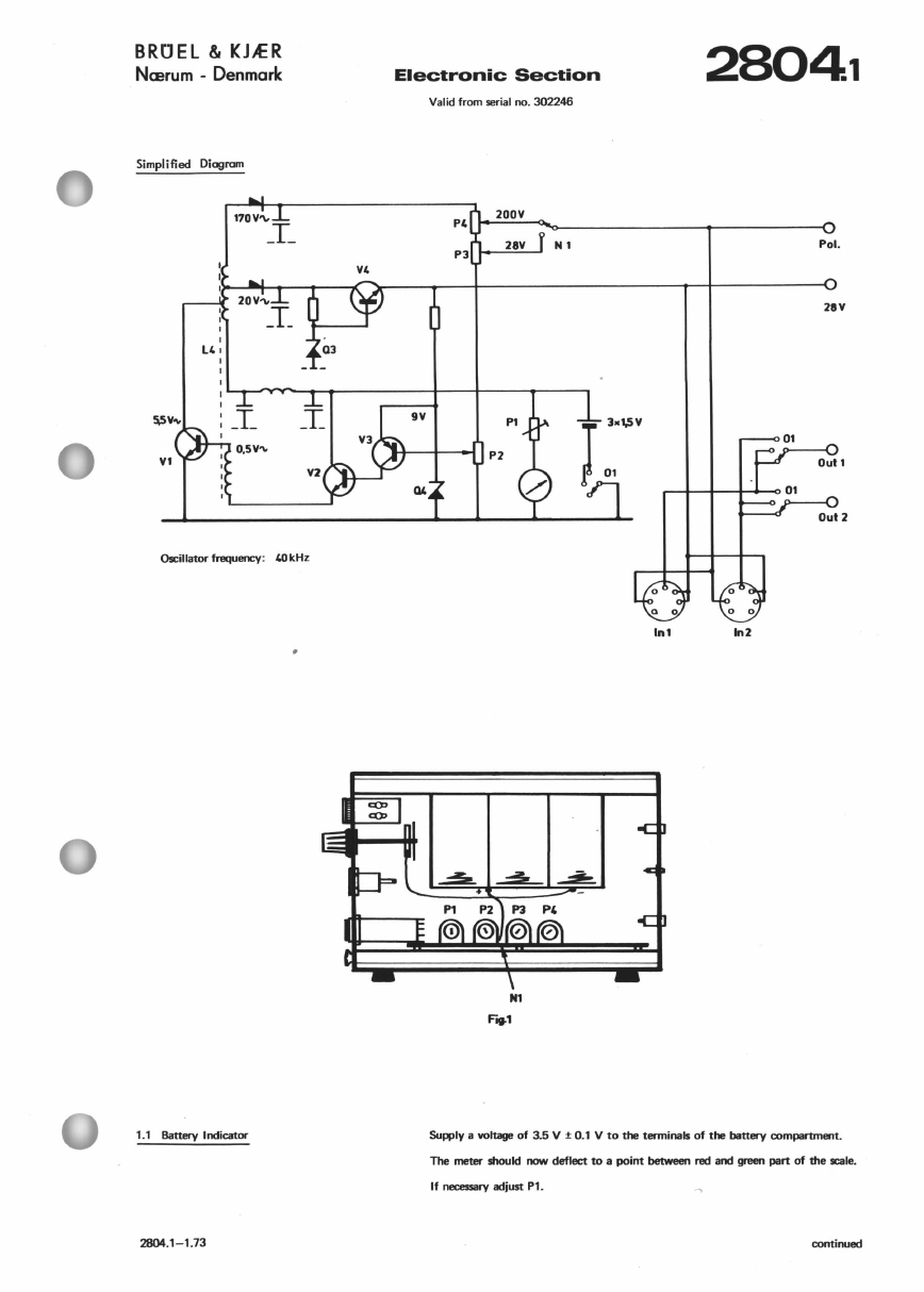
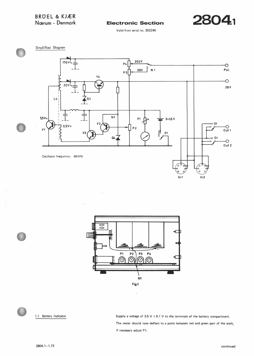
Electronic Section
Position of Components
Parts
list
Circuit Diagram
2804.1
2804.2
2804.3
2804.4
2804
Tum
the
thumb screw on
the
front
plate anti-clockwise. The bottom plate can then be slid backwards and removed.
Unscrew the
two
3
mm
screws
on
the
back plate. The two side plates can then be slid backwards and removed.
Battery Change
Unscrew the upper 3
mm
screw
on
the
back plate and slid the
top
plate backwards. The batteries can then easily be changed.
Trouble Shooting
If
any problems should occur with this instrument, then first check
the
DC
working voltages from
the
Power Supply. Then use
the
Block Diagram
in
order
to
localize
the
trouble
to
be located
in
one specific circuit.
When a fault has
been
found
and
corrected,
the
voltages and adjustment which are influenzed
by
the
correction must be rechecked,
and
the
instrument controlled
to
see
if
all
basic functions are fulfilled.
The tolerances stated
in
the
instructionscan only be used as a guide for adjustment and control.
Any deviations must not
be
corrected without being sure,
that
the tolerances,
of
the
instruments used for making
the
adjustment, are
so small as
to
have
no
influence
on
the
measurements.
The instructions in this Manual
are
given
purely as a guide
to
the service
of
the
equipment
. Some faults, as for example, small
deviations
in
tolerances require for their corrections special control equipment and extensive experience,and
in
these cases it
is
necessary
to
send
the
instrument
to
the
factory.
Voltages
at
various points
throughout
the apparatus are indicated on the circuit diagram and
the
simplified diagram
in
the
service
instructions. These voltages are typical nominals only and with
the
exception
of
stabilized power supply voltages, may vary
considerably from apparatus
to
apparatus.
Spare Parts
Please state serial number
of
apparatus when spare parts are ordered.
2804 · 9.79