Tunstall 1423801 User manual

English Doc. 346 80 21-84. Version 2. Revision 10.2023
Interconnected smoke alarm
Part no. 1423801
Installation guide
Works with Lifeline Digital, Careline, Lifeline Smart Hub and Lifeline Vi/Vi+

Table of Contents
1. Safety instructions ........................................................................................................................................ 4
2. Introduction ................................................................................................................................................. 5
2.1. Functionality ......................................................................................................................................... 5
2.1.1. Power on/off .................................................................................................................................. 5
2.1.2. Button actions ................................................................................................................................ 5
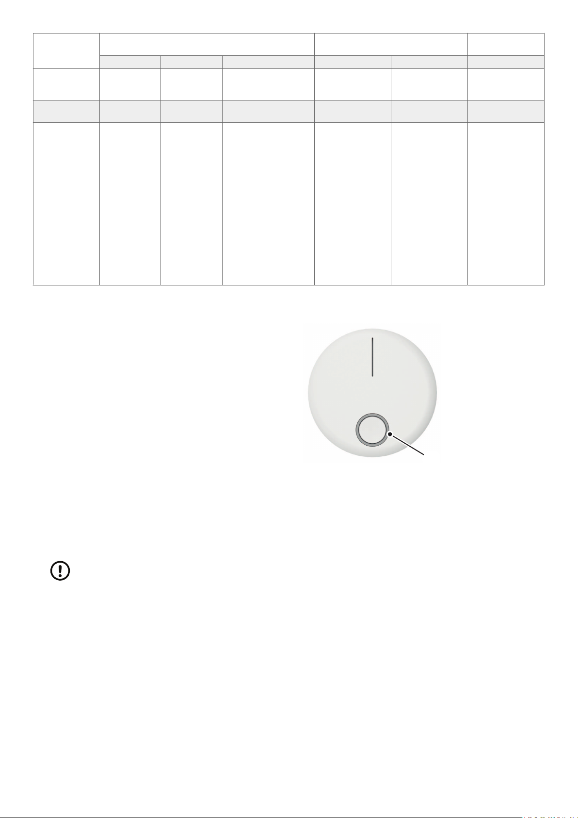
2.1.3. LED indicator ................................................................................................................................. 6
2.1.4. Guide light ..................................................................................................................................... 6
2.1.5. Cancel function .............................................................................................................................. 6
2.1.6. Speech messages ........................................................................................................................... 6
2.1.6.1. Languages .............................................................................................................................. 6
2.1.6.2. Change language .................................................................................................................... 7
2.1.6.3. Messages ................................................................................................................................ 7
2.1.7. Alarm state .................................................................................................................................... 7
2.1.8. Communication tests ...................................................................................................................... 7
2.2. What´s in the box .................................................................................................................................. 8
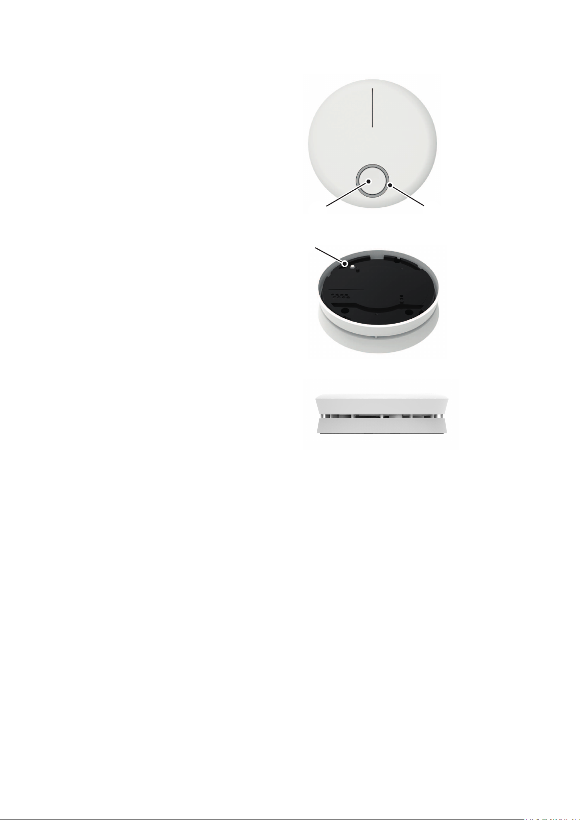
3. Overview ..................................................................................................................................................... 9
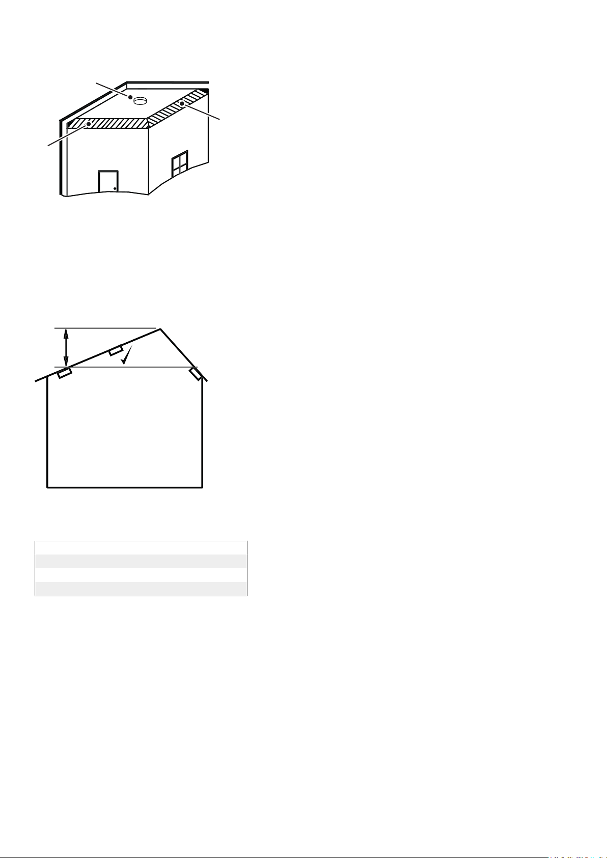
4. Recommended placement ......................................................................................................................... 10
4.1. Ceiling mounting ................................................................................................................................ 10
4.2. On a sloping ceiling ............................................................................................................................ 11
4.3. Environmental properties ..................................................................................................................... 11
4.4. Unsuitable places for installation .......................................................................................................... 11
5. Registration ............................................................................................................................................... 12
5.1. Interconnect smoke alarms .................................................................................................................. 12
5.2. Delete interconnected smoke alarm ..................................................................................................... 12
5.3. Replacing a smoke alarm ..................................................................................................................... 13
5.3.1. Replace a controller device ........................................................................................................... 13
5.3.2. Replace a worker device ............................................................................................................... 13
6. Connecting to hub ..................................................................................................................................... 14
6.1. Connect to Lifeline Digital ................................................................................................................... 14
6.2. Connect to Careline ............................................................................................................................ 16
6.3. Connect to Lifeline Smart Hub ............................................................................................................. 18
6.4. Connect to Lifeline Vi/Vi+ .................................................................................................................... 20
6.5. Replacing the hub ............................................................................................................................... 21
7. Installation ................................................................................................................................................. 22
7.1. Configure location code ...................................................................................................................... 22
7.1.1. Configure location in DMP ............................................................................................................ 22
7.1.1.1. Configure location for Lifeline Digital ...................................................................................... 22
7.1.1.2. Configure location for Careline ............................................................................................... 23
7.1.1.3. Configure location for Lifeline Smart Hub ................................................................................ 23
7.1.2. Configure location in Tunstall+ App .............................................................................................. 23
7.1.3. Configure location in PC Connect ................................................................................................. 24
7.1.3.1. Configure location for Lifeline Vi/Vi+ ...................................................................................... 24
8. Disconnecting from hub ............................................................................................................................. 25
8.1. Disconnect from Lifeline Digital ........................................................................................................... 25
8.2. Disconnect from Careline .................................................................................................................... 26
8.3. Disconnect from Lifeline Smart Hub ..................................................................................................... 27
8.4. Disconnect from Lifeline Vi/Vi+ ............................................................................................................ 27
9. Maintenance and cleaning .......................................................................................................................... 28
9.1. Manual alarm test ............................................................................................................................... 28
9.2. Communication test ............................................................................................................................ 28
9.3. Battery ............................................................................................................................................... 29
9.3.1. Battery life ................................................................................................................................... 29
9.3.2. Low battery .................................................................................................................................. 29
9.4. Cleaning ............................................................................................................................................. 29
10. Disposal and recycling .............................................................................................................................. 30
11. Technical data .......................................................................................................................................... 31

1. Safety instructions
• The smoke alarm generates a powerful and shrill noise, which can be harmful to your ears. Keep at least a 50 cm
distance from the alarm while performing the function test.
• Never paint the smoke alarm.
• Smoke alarms will always identify the smoke of a fire. They will not identify the flame itself.
• Smoke alarms are not able to extinguish any fire. In case of alarm evacuate the building and call the fire service.
• The smoke alarm is capable to survey only a defined zone around its own position. For optimum protection, ensure
that a sufficient number of alarms are installed in the area to be monitored.
• The smoke alarm has a built-in battery, please dispose properly according to WEEE.
• Do not dispose into a fire or a hot oven, or by mechanically crushing or cutting. It could lead to explosion or
leakage of flammable liquids or gases.
• Do not use, store or carry it any place where it may be exposed to extremely high temperature or extremely low air
pressure.
• Never charge the battery that comes with the smoke alarm.
• Do not use other battery than the built-in.
4

2. Introduction
The interconnected smoke alarm is a wireless smoke alarm designed to detect smoke and give an early warning if
a fire should start. It can easily be connected to other smoke alarms to form a system. If one smoke alarm detects
smoke and triggers an alarm, radio signals are sent to other smoke alarms and all alarms will sound. The system can
include up to 15 smoke alarms (including controller device).
The smoke alarm has a range of up to 100 metres depending on its position, the design of the building and the
materials used in the building. A communication test should always be performed after installation.
The smoke alarm can be used stand-alone or connected to a Tunstall hub through social alarm radio to communicate
with the alarm receiver or ARC (Alarm Receiving Center) operator.
2.1. Functionality
• Battery powered interconnected radio smoke alarm using the scattered light method
• Early and reliable fire detection through precise adjustment of the release characteristics
• Outstanding operating safety by intelligent analysis of the measuring chamber signal
• Light guide for evacuation
• Voice alarm gives clear indication of what the danger is and where it is located
• Provides precise smoke detection and powerful alarm signal of more than 85 dB(A) close to the alarm in case of fire
• Operating temperature range –10°C up to +55°C
• Wireless linking to a hub, via 869 MHz European Social Alarm Frequency
• Wireless interconnection between smoke alarms using 868 MHz Frequency
• Typical radio frequency range 100 metres in open air
2.1.1. Power on/off
The smoke alarm is delivered with the bracket mounted in a shipping position (upside down).
Power on
• Attach the bracket
or
• Without bracket: long press front button (over 6 seconds)
When powered on, the green LED is flashing.
Power off
• Remove the bracket and long press the front button (over 6 seconds)
The red LED is flashing and then it powers off with a down sweep tone.
2.1.2. Button actions
The smoke alarm has a big front button and a smaller button on the back.
• Short press - press 0.2 to 1 seconds
• Long press 1 - press over 3 seconds, less than 6 seconds
• Long press 2 - press over 6 seconds
5

Front button Back button Front button +
back button
Long press 2 Long press 1 Short press Long press 2 Short press Long press 1
With bracket
in normal
state
--- Alarm test Communication test --- --- ---
With bracket
in alarm state
--- --- Halt alarm temporarily --- --- ---
Without
bracket
Power
ON/OFF
--- In registration mode
Select language
Delete registra-
tion
Send registration
packet to both
hub and smoke
alarm controller.
In registration
mode
Set language (in
the language set-
ting mode)
Even if the de-
vice has already
registered with
hub, send regis-
tration packet
(resume)
Interconnection
registration
mode.
2.1.3. LED indicator
Red/Green LED (1) is located on the front of the device.
1
2.1.4. Guide light
A white guide light will illuminate the floor if an alarm is triggered.
2.1.5. Cancel function
The smoke alarm has a cancel function, which allows you to turn off the alarm signal in the event of a false alarm.
NOTE
When you turn off the alarm signal, the LED will stay on for 10 minutes.
When the smoke alarm is in the smoke alarm state, you can halt sounding temporarily by pressing the front button
(0.2 to 1 seconds). The temporary alarm halt duration is 10 minutes. After 10 minutes, the smoke alarm returns to
normal operating mode (it will start sounding again if the fire alarm state remains).
2.1.6. Speech messages
2.1.6.1. Languages
The smoke alarm supports 9 languages.
These are the languages that the smoke alarm speaks during setup, alerts and emergency alarms.
6

1 (default) English
2 Swedish
3 Norwegian
4 Danish
5 German
6 French
7 Spanish
8 Finnish
9 Dutch
2.1.6.2. Change language
NOTE
Language can only be changed on the controller smoke alarm. All other smoke alarms follows the
controller's language settings.
a) Press and hold both front and back button over 3 seconds to enter "Registration mode".
b) Short press the front button (0.2 to 1 seconds) to enter "Language mode". The smoke alarm beeps and the
currently set language is announced. The green and red LED are also flashing.
c) Short press the front button (0.2 to 1 seconds) to change language.
d) Short press the back button (0.2 to 1 seconds) to set language.
When the language is set, the smoke alarm beeps and announces "Registration mode, Swedish".
e) Press and hold both front and back button over 3 seconds to enter "Normal mode".
2.1.6.3. Messages
1. Warning Fire Alarm
2. Warning Fire Alarm in another room
3. Check detector
4. Low battery
5. Test completed successfully
6. No connection
7. Registration mode
8. Registration completed successfully
9. Language mode
10. Normal mode
11. Registration delete completed successfully
12. Error
2.1.7. Alarm state
If a smoke alarm detects smoke an alarm is triggered. The device will beep and announce "Warning Fire Alarm", and
the LED is flashing red.
A white guide light will illuminate the floor.
Using the interconnection function, other smoke alarms will also be beeping and flashing red. They will also announce
"Warning Fire Alarm in another room".
When the smoke alarm restores from alarm state, it will stop beeping and flashing, and notify restore status to the
hub.
2.1.8. Communication tests
Communication test (auto presence) - Every 23 hours the communication between the hub and the smoke alarms is
automatically tested.
7

Communication test (interconnection) - Every 25 hours the communication between the interconnected smoke
alarms is automatically tested.
2.2. What´s in the box
The smoke alarm box contains:
• Smoke alarm (built-in, non-replaceable batteries included)
• Bracket (the smoke alarm is delivered with the bracket mounted in a shipping position (upside down)
8

3. Overview
•Front
1. Front button
2. LED (green/red)
21
•Back
3. Back button
3
•Side
9

4. Recommended placement
1
1
5
2 3
1
4
1. Bedroom
2. Bathroom
3. Kitchen
4. Living room
5. Dining room
For minimum protection
- Smoke alarm on each storey
- Every 7.5 metres of hallways and escape routes
- Within 3 metres of all bedroom doors
For recommended protection (in addition to the above):
- Smoke alarms in every room (except kitchens and bath-
rooms)
- Heat alarms located in kitchens, garages etc. within
5.3m of potential fire sources
4.1. Ceiling mounting
Hot smoke rises and spreads out, so a central ceiling position is the recommended location. The air is “dead” and
does not move in corners, therefore smoke alarms must be mounted away from corners. Keep at least 300mm from
10

walls and corners. Additionally, mount the alarm at least 300mm from any light fitting or decorative object which
might prevent smoke entering the smoke alarm. We do not recommend wall mounting of smoke alarms.
2
2
1
1. Ideal in centre of ceiling
2. Dead air surfaces never within 300mm of any corner
4.2. On a sloping ceiling
With a sloping or peaked ceiling install a smoke alarm within 600mm of the peak (measured vertically). If this height is
less than 600mm it is regarded as being flat.
x
x
4.3. Environmental properties
Intended use Indoor
Mounting position Ceiling only
Operating temperature -10 to +55 degrees Celsius
Operating humidity Max: 90%
4.4. Unsuitable places for installation
To avoid false alarms and malfunctions, never install the smoke alarm:
• inside rooms where heavy vapor, dust or smoke develop under regular conditions (bath, kitchen).
• near to fireplaces and open fires.
• near to ventilation systems. The flow of air may deviate the smoke so it will never reach the alarm.
• near to neon lamps and energy saving lamps. The starter may cause false alarms by electric fields that arise when
turning on the lamp (minimum distance: 50cm)
• in edges, for example house gables, in such areas smoke free air can accumulate and the identification of fire is
hindered
• inside rooms with temperatures beneath -10°C or above +55°C
11

5. Registration
The smoke alarm can easily be connected to other smoke alarms to form a system. First, you need to register a
controller device that you can connect the other smoke alarms to.
NOTE
Even if you only use one smoke alarm, you still have to register it as the controller.
NOTE
If you replace the controller device, you have to connect the new controller to the hub and all
interconnected smoke alarms must be deleted and then connected to the new controller. For further
instructions, see Replacing a smoke alarm, page 13.
a) Select one smoke alarm to be the controller.
b) Mark the device so you can easily identify it later.
c) Press and hold both the front and back button on the smoke alarm (over 3 seconds less than 6 seconds) to
activate "Registration mode".
The device beeps and announces “Registration mode”, and the green LED is flashing. This smoke alarm has now
become the controller.
d) If you want to change to a language other than English (default), see Change language, page 7.
5.1. Interconnect smoke alarms
When you have registered a controller device, you can connect the other smoke alarms to it.
NOTE
All smoke alarms that will be included in the system needs to be connected to the controller device.
a) Make sure that the controller is in Registration mode or press and hold both the front and back button (over 3
seconds less than 6 seconds) to activate "Registration mode".
The device beeps and announces “Registration mode”, and the green LED is flashing.
b) Select another smoke alarm to connect to the controller.
c) Power on the device.
d) Short press the back button (0.2 to 1 seconds). The smoke alarm confirms with a short beep.
When registration is completed the smoke alarm beeps again and announces “Registration completed success-
fully” and the green LED lights up.
If registration is not completed (no reply from controller) the smoke alarm beeps and announces “Error” and the
red LED lights up.
Repeat the steps above for all smoke alarms included in the system.
When registration is completed, press and hold both front and back button on the controller for over 3 seconds to
enter "Normal mode".
5.2. Delete interconnected smoke alarm
NOTE
Make sure the smoke alarm is in normal mode before you delete it.
12

NOTE
If you replace the controller, all interconnected smoke alarms need to be reinstalled.
• To delete an interconnected smoke alarm, press and hold the back button for at least 6 seconds.
When registration is deleted the device announces ”Registration delete completed successfully” and the green
LED lights up.
5.3. Replacing a smoke alarm
5.3.1. Replace a controller device
a) Delete the old controller device according to the instructions in Delete interconnected smoke alarm, page 12.
b) Press and hold both the front and back button on the new controller device (over 3 seconds less than 6 seconds)
to activate "Registration mode".
The device beeps and announces “Registration mode”, and the green LED is flashing. This smoke alarm has now
become the controller.
c) Connect the new controller to the hub according to the instructions in Connecting to hub, page 14.
NOTE
All smoke alarms included in the system needs to be connected to the new controller device accord-
ing to the instructions in Interconnect smoke alarms, page 12.
5.3.2. Replace a worker device
a) Delete the old worker device according to the instructions in Delete interconnected smoke alarm, page 12.
b) Connect the new worker device to the controller device according to the instructions in Interconnect smoke
alarms, page 12.
c) Connect the worker device to the hub according to the instructions in Connecting to hub, page 14.
13

6. Connecting to hub
The procedure for connecting the smoke alarm depends on the hub.
NOTE
If several smoke alarms are included in the system, they must all be connected to the hub.
6.1. Connect to Lifeline Digital
a) Make sure that Lifeline Digital and the smoke alarm are
switched on.
b) Press and hold the green button , then press and hold
the yellow button and red button .
12 3
c) Release all buttons when you hear a rising sound signal
and the device announces "Programming mode".
The buttons start to flash in unison to indicate that the
device is in programming mode.
NOTE
The device automatically exits program-
ming mode if no further buttons are
pressed.
d) Press and hold the red button .
14

e) Release the button when the device announces "Au-
to pairing mode" to automatically connect the smoke
alarm to an available radio sensor position or keep the
button pressed down until the device announces the
number of the specific radio position that you want to
connect to.
3
f) When the device announces "Activate transmitter now",
short press the back button (0.2 to 1 seconds) on the
smoke alarm.
The device announces:
• "Operation succeeded" if a connection was success-
fully established
• "Operation failed" followed by an error code if a con-
nection was not established:
◦" Error code One" if the radio code could not be
stored in the device
◦" Error code Two" if the radio code was already
stored in the device
• "Battery low" if the battery in the smoke alarm is low
NOTE
If the registration fails, enter program-
ming mode again and short press the
back button (0.2 to 1 seconds) on the
smoke alarm.
4
15

g) Press the green button to exit programming mode.
NOTE
To upload the new settings to DMP, you
can either press and hold the yellow
Extra button1 on Lifeline Digital for ap-
proximately 3 seconds to manually con-
nect to DMP or wait for Lifeline Digital
to connect to DMP automatically.
NOTE
It is important to note in which room
each smoke alarm will be placed. After
installation, use DMP or Tunstall+ to
configure the location for each smoke
alarm in the system. If smoke is detec-
ted, the smoke alarm's location is sent
to the alarm receiver and is also an-
nounced by the voice alarm to give a
clear indication of where smoke is de-
tected. To configure the location in the
system, see Configure location code,
page 22.
1
h) Make sure the smoke alarm is working by pressing the
front button for at least 4 sec. A test signal tone and the
message "Warning Fire Alarm" is generated. The red
LED is also flashing. The signal tone is generated for 1
minute, or until you terminate the test by pressing the
front button.
If no signal tone is generated, please let a few minutes
pass, then retest.
Also make sure that an alarm sounds from Lifeline Digital
and that the connected alarm receiver has received the
alarm.
6.2. Connect to Careline
a) Make sure that Careline and the smoke alarm are switch-
ed on.
b) Press and hold the green button on the Careline.
1This function can be reassigned to the green Cancel button by your supplier. Contact your supplier if you have any questions.
16

c) Press and hold also the grey and the red button
and keep all buttons pressed until a rising sound signal
is heard. Then release all buttons.
1 2
3
d) The device is now in programming mode, indicated by a
rolling light between the LED’s.
NOTE
If no further buttons are pressed, the
device will automatically exit the pro-
gramming mode. If this happens, you
need to start over from the start
e) Press and hold the red button . Wait until the device
announces the number of the specific radio position that
you want to connect to. Then release the button.
f) Short press the back button (0.2 to 1 seconds) on the
smoke alarm.
An acknowledgement signal is heard from the hub when
the radio code is received.
NOTE
If the registration fails, enter program-
ming mode again and short press the
back button (0.2 to 1 seconds) on the
smoke alarm.
4
g) Press the green button on Careline to exit program-
ming mode.
NOTE
To upload the new settings to DMP,
you can either press and hold the grey
button on Careline for approximately 3
seconds to manually connect to DMP
or wait for Careline to connect to DMP
automatically.
17

NOTE
It is important to note in which room
each smoke alarm will be placed. After
installation, use DMP or Tunstall+ to
configure the location for each smoke
alarm in the system. If smoke is detec-
ted, the smoke alarm's location is sent
to the alarm receiver and is also an-
nounced by the voice alarm to give a
clear indication of where smoke is de-
tected. To configure the location in the
system, see Configure location code,
page 22.
h) Make sure the smoke alarm is working by pressing the
front button for at least 4 sec. A test signal tone and the
message "Warning Fire Alarm" is generated. The red
LED is also flashing. The signal tone is generated for 1
minute, or until you terminate the test by pressing the
front button.
If no signal tone is generated, please let a few minutes
pass, then retest.
Also make sure that an alarm sounds from Careline
and that the connected alarm receiver has received the
alarm.
Transmitter position Alarm type
Transmitter 1 Care alarm
Transmitter 2 Care alarm
Transmitter 3 Care alarm
Transmitter 4 Fire alarm
Transmitter 5a. Door alarm
Transmitter 6a. Bed alarm
Transmitter 7a. Carpet alarm
Transmitter 8 Passive alarmb.
Transmitter 9 Care alarm
Transmitter 10 Care alarm
Transmitter 11 Care alarm
Transmitter 12 Care alarm
Transmitter 13 Care alarm
Transmitter 14 Care alarm
Transmitter 15 Care alarm
Transmitter 16 Care alarm
a.This only works if your alarm receiver is able to receive these types of alarms. If not, please contact Tunstall support, +46 (0) 20 - 66 11 11.
b.If you want this alarm to be sent directly when detected you need to change the timeout for passive alarms. This is handled in the Careline Edith
software in the tab Timers. In the field under Passive alarm (hours) enter 0.
6.3. Connect to Lifeline Smart Hub
a) Make sure that Lifeline Smart Hub and the smoke alarm
are switched on.
18

b) Press and hold the green Cancel button for five sec-
onds until you hear a confirmation tone. Then release
the button.
The device announces: "Programming mode" and the
red Help button flashes slowly.
1
2
c) Press and hold the green Cancel button on the de-
vice for three seconds until you hear the announcement
"Registration mode" and the red Help button flashes
rapidly. Then release the button.
NOTE
The device automatically exits program-
ming mode if no further buttons are
pressed.
d) Short press the back button (0.2 to 1 seconds) on the
smoke alarm.
The Lifeline Smart Hub will confirm receipt of the
smoke alarm signal by announcing "Smoke detector
registered".
NOTE
If the registration fails, enter program-
ming mode again and short press the
back button (0.2 to 1 seconds) on the
smoke alarm.
3
e) Press the green Cancel button to exit programming
mode. A confirmation tone confirms exiting the pro-
gramming mode. The red Help button lights up continu-
ously.
NOTE
To upload the new settings to DMP, you
can either press the green Cancel but-
ton on the Lifeline Smart Hub or wait for
the device to connect to DMP automati-
cally.
1
19

NOTE
It is important to note in which room
each smoke alarm will be placed. After
installation, use DMP or Tunstall+ to
configure the location for each smoke
alarm in the system. If smoke is detec-
ted, the smoke alarm's location is sent
to the alarm receiver and is also an-
nounced by the voice alarm to give a
clear indication of where smoke is de-
tected. To configure the location in the
system, see Configure location code,
page 22.
f) Make sure the smoke alarm is working by pressing the
front button for at least 4 sec. A test signal tone and the
message "Warning Fire Alarm" is generated. The red
LED is also flashing. The signal tone is generated for 1
minute, or until you terminate the test by pressing the
front button.
If no signal tone is generated, please let a few minutes
pass, then retest.
Also make sure that an alarm sounds from Lifeline Smart
Hub and that the connected alarm receiver has received
the alarm.
6.4. Connect to Lifeline Vi/Vi+
a) Make sure that Lifeline Vi/Vi+ and the smoke alarm are
switched on.
b) Press and hold the green Cancel button for five sec-
onds until you hear a confirmation tone. Then release
the button.
The device announces: "Programming mode" and the
red Help button flashes slowly.
1
2
c) Press and hold the green Cancel button on the de-
vice for three seconds until you hear the announcement
"Registration mode" and the red Help button flashes
rapidly. Then release the button.
NOTE
The device automatically exits program-
ming mode if no further buttons are
pressed.
20

d) Short press the back button (0.2 to 1 seconds) on the
smoke alarm.
The Lifeline Vi/Vi+ will confirm receipt of the smoke
alarm signal by announcing "Smoke detector regis-
tered".
NOTE
If the registration fails, enter program-
ming mode again and short press the
back button (0.2 to 1 seconds) on the
smoke alarm.
3
e) Press the green Cancel button to exit programming
mode. A confirmation tone confirms exiting the pro-
gramming mode. The red Help button lights up continu-
ously.
NOTE
It is important to note in which room
each smoke alarm will be placed. After
installation, use PC Connect to config-
ure the location for each smoke alarm
in the system. If smoke is detected, the
smoke alarm's location is sent to the
alarm receiver and is also announced
by the voice alarm to give a clear in-
dication of where smoke is detected.
To configure the location in the system,
see the Lifeline Vi/Vi+ "Installation and
Programming Guide".
1
f) Make sure the smoke alarm is working by pressing the
front button for at least 4 sec. A test signal tone and the
message "Warning Fire Alarm" is generated. The red
LED is also flashing. The signal tone is generated for 1
minute, or until you terminate the test by pressing the
front button.
If no signal tone is generated, please let a few minutes
pass, then retest.
Also make sure that an alarm sounds from Lifeline Vi/Vi+
and that the connected alarm receiver has received the
alarm.
6.5. Replacing the hub
If the hub is replaced you need to connect all smoke alarms to the new hub.
a) Remove the old hub.
b) Install the new hub.
c) Connect all smoke alarms to the new hub according to the instructions in Connecting to hub, page 14.
21
Table of contents
Other Tunstall Smoke Alarm manuals