Tunze 7607/2 User manual

1
x7607.2888
10/2008
Water Level Alarm
7607/2
Gebrauchsanleitung
Instructions for Use
Mode d’emploi

2
TUNZE®Aquarientechnik GmbH
Seeshaupter Straße 68
D - 82377 Penzberg
Germany
Tel: +49 8856 2022
Fax: +49 8856 2021
www.tunze.com
Email: info@tunze.com
Inhalt
Allgemeines
Lieferform / Funktion
Sicherheitshinweise
Platzwahl für Steuergerät 7607/2
Befestigung
7607/2 mit Unterschrankanlagen
7607/2 mit Innenlteranlagen
Platzwahl für Sensoren
Halterung an senkr. Aquarienscheibe
Sensorhalterung mit Verlängerung
Halterung an waager. Aquarienscheibe
Halterung an Glasscheibe kleben
Leuchtdioden (LED) am Controller 7607/2
Abstecken des Verbindungskabels
Welche Geräte anschließen?
Sensoren
Inbetriebnahme bei Unterschrankanlagen
Inbetriebnahme bei Innenlteranlagen
Funktionstest und Wartung
Pege der Sensoren
Teileliste - Ersatzteile
Garantie
Störungen
Entsorgung
Seite
4
6
8
10
12
14
16
18-20
22
24
26-28
30
32
34
36
38
40
42
44
46
48
50
52-54
56
®

3
Page
5
7
9
11
13
15
17
19-21
23
25
27-29
31
33
35
37
39
41
43
45
47
49
51
53-55
56
Table of Contents
General aspects
Condition delivered / function
Safety instructions
Location for control unit 7607/2
Attachment
7607/2 in aquarium cabinets
7607/2 in internal lter plants
Location for sensors
Holding device on vertical aquarium pane
Sensor holding device with extension
Holding device on horizontal
aquarium pane
Sticking the holding device
on the glass pane
Light-emitting diodes (LEDs)
on Controller 7607/2
Disconnecting the connecting cable
Which devices can be connected ?
Sensors
Initial operation in aquarium cabinets
Initial operation in internal lter plants
Function test and maintenance
Servicing the sensors
List of parts / spare parts
Guarantee
Failures
Disposal
Page
5
7
9
11
13
15
17
19-21
23
25
27-29
31
33
35
37
39
41
43
45
47
49
51
53-55
56
Sommaire
Généralités
Contenu / Fonction
Sécurité d’utilisation
Placement de la commande 7607/2
Fixation
7607/2 en ltrations sous aquarium
7607/2 en ltrations internes
Placement des capteurs
Fixation sur vitre verticale
Fixation avec prolongateur
Fixation sur renfort horizontal
Fixation par collage
Diodes LED sur Controller 7607/2
Déconnexion du câble d’alimentation
Quels appareils peut-on raccorder ?
Capteurs
Mise en service en ltrations sous aq.
Mise en service en ltrations internes
Test des fonctions et entretien
Entretien des capteurs
Liste des pièces
Garantie
Que faire si… ?
Gestion des déchets

4
Allgemeines
Der Water Level Alarm ist ein
Wasserstandsfehlmelder, der als Ergänzung für
Wassernachfüllanlagendient. ImStörfall werdenalle
über die Schaltdose angeschlossenen Verbraucher
abgeschaltet, außerdem ertönt ein Warnsignal und
eine rote Diode leuchtet auf.
(1) Er schützt Filteranlagen im Aquarium oder im
Unterschrank vor Trockenlauf und kann Schäden
vermeiden, die z.B. durch das unbeabsichtigte
Leerpumpen des Filterbehälters entstehen könnten.
Aber auch bei Wasserstandsreglern mit fehlendem
Nachfüllwasser kann der Water Level Alarm vor
Trockenlauf schützen.
(2) In Unterschrankanlagen kann er den
Ablauf überwachen und vor Überlauf des
Aquariums schützen, z.B. beim Verstopfen des
Ablaufrohrsystems.
(3) Der Water Level Alarm kann bestehende
Nachfüllanlagen (Osmolator) mit großem
Wasservorrat überwachen und als Überlaufschutz
arbeiten.
Bitte beachten Sie: Der Water Level Alarm ist kein
Ersatz für Installations- oder Wartungsmängel Ihrer
Anlage.

5
General aspects
The Water Level Alarm is used as a supplement to
water relling systems. In the event of a failure, the
switched socket outlet switches off all connected
electrical devices; in addition an alarm is sounded
and a red LED lights up.
(1) It protects lter systems in the aquarium or in
the cabinet against running dry and can prevent
damage, which might occur by accidental emptying
of the sump, for example. But, the Water Level
Alarm can also provide protection against running
dry for water level regulators lacking rell water.
(2) In aquarium cabinets, the unit can monitor
the outlet and can protect the aquarium against
overow when the drain pipe system is clogged, for
example.
(3) The Water Level Alarm can monitor relling
systems (Osmolator) with large water store tanks
and can operate as an overow protection.
Notice: The Water Level Alarm is not a remedy for
defects in installation or maintenance.
Généralités
Water Level Alarm est un indicateur de défaut de
niveau d’eau complémentaire aux installations de
régulation de niveau. Lors d’un défaut, tous les
appareillages raccordés à la prise commandée se
retrouvent hors service, le défaut est signalé par un
avertisseur sonore et une diode LED rouge.
(1) Protège les ltrations internes ou sous aquarium
d’un fonctionnement à sec, évite les dommages
aux appareillages pouvant résulter d’un manque
d’eau dans la cuve de ltration. De même et pour
des systèmes de rajout d’eau sans aucune sécurité
anti-débordement, l’indicateur défaut de niveau
prévient tout disfonctionnement.
(2) En ltration sous aquarium, permet une
surveillance du déversoir en évitant le débordement
de l’aquarium lors de l’obstruction de ce déversoir.
(3) Permet la surveillance du fonctionnement de
l’Osmolator lors de l’utilisation d’une cuve de rajout
d’eau de grande capacité, évite le débordement de
l’aquarium lors d’un disfonctionnement.
Veuillez observer : Water Level Alarm ne
représente pas la solution à une installation de
mauvaise conception technique ou à un manque de
surveillance.

6
Lieferform
Der Water Level Alarm hat 3 Sensoren: Einen
Trockenlaufsensor und 2 Überlaufsensoren. Jeder
Sensor hat einen Halter zum Kleben mit Silikon oder
zum Klemmen an waagerechten oder senkrechten
Scheiben. Die Halter können auch zusammengefügt
werden. Die Steuereinheit hat eine optische
Anzeige für jeden Sensor kombiniert mit Warnton.
Die Schaltsteckdose hat eine Schaltleistung bis zu
230V / 1.800 W (bei 115V / 900 W).
Funktion
Nach richtiger Installation kann der Water Level
Alarm (3) verschiedene Wasserstände überwachen
(1). Über- oder unterschreitet ein Wasserstand
die gesetzten Grenzen, werden in einem
solchen Störfall alle über die Schaltsteckdose (2)
angeschossenen Geräte abgeschaltet, außerdem
ertönt ein Warnsignal und eine rote Warnlampe
(3) leuchtet auf. Nach der Behebung der Ursache
kann am roten Knopf des Steuergerätes (3) eine
Rücksetzung (Reset) erfolgen. Das Gerät ist
wieder betriebsbereit für die Überwachung. Die
Schaltsteckdose führt wieder Strom.

7
Delivery condition
The Water Level Alarm has three sensors: one run-
dry protection sensor and two overow sensors.
Each sensor comes with a holding device which can
be adhered with silicone or clamped to horizontal
or vertical panes. The holding devices can also be
combined. The control unit has an LED indicator for
each sensor combined with an alarm. The switched
socket outlet has a capacity up to 230 V / 1800 W
(at 115 V, 900 W).
Functions
After correct installation, the Water Level Alarm
(3) can monitor three different water levels (1). If a
water level falls short of or exceeds the limits set,
all units connected through a switched socket outlet
(2) are switched off, and in addition a warning signal
is sounded and a red warning lamp lights up (3).
After removal of the cause, use the red button on
the control unit (3) for reset. Subsequently, the unit
is ready for monitoring again. The switched socket
outlet is energised again.
Contenu
Water Level Alarm comporte 3 capteurs : un
capteur contre une marche à sec et 2 capteurs
anti-débordement. Chaque capteur possède un
support à coller ou à xer sur une paroi verticale
ou horizontale. Les supports peuvent être reliés
entre eux. La commande électronique intègre une
signalisation optique pour chaque capteur ainsi
que sonore. La prise commandée est dotée d’un
pouvoir de coupure jusqu’à 230 V / 1.800 W (115 V
/ 900W).
Fonction
Après une installation dans les règles de l’ensemble
du système, Water Level Alarm (3) peut surveiller
3 niveaux d’eau différents (1). Si un des niveaux
devait dépasser ou se trouver en-dessous du
niveau normal, le défaut généré stoppe tous les
appareillages raccordés à la prise commandée
(2). Un signal sonore retentit et la diode LED rouge
(3) correspondante s’allume. Après élimination du
défaut, une action sur le bouton rouge «Reset» (3)
placé sur le Controller efface le défaut. L’appareil
est à nouveau prêt pour la surveillance, la prise
commandée est à nouveau alimentée.

8
Sicherheitshinweise
Water Level Alarm nur für Aquarien einsetzen, der
Betrieb im Freien ist nicht zulässig.
Steuergerät 7607/2 nur an trockener und gut
belüfteter Stelle anbringen! (1)
Nicht in die Nähe von Heiz- und Wärmequellen
aufstellen (2), Umgebungstemperatur max. + 35°C.
Magnetscheibenreiniger oder andere Magnete
nicht in die Nähe des Sensors bringen, sonst
Funktionsstörung möglich, mind. 20 cm Abstand
halten (3).
Vor Inbetriebnahme prüfen, ob Betriebsspannung
mit Ihrer Netzspannung übereinstimmt.
Vor Reinigung und Wartung Netzstecker abziehen.
Beschädigte Kabel nicht selbst reparieren, sondern
Geräte zur Reparatur geben.
Water Level Alarm nicht unbeaufsichtigt
betreiben.
Dieses Gerät ist für Benutzer (einschl. Kinder)
mit eingeschränkten physischen, sensorischen
oder psychischen Fähigkeiten bzw. ohne jegliche
Erfahrung oder Vorwissen nur dann geeignet,
wenn eine angemessene Aufsicht oder ausführliche
Anleitung zur Benutzung des Geräts durch eine
verantwortliche Person sichergestellt ist. Achten Sie
darauf, dass Kinder nicht mit dem Gerät spielen (4).

9
Safety instructions
Use Water Level Alarm for aquariums only - outdoor
operation is not permissible.
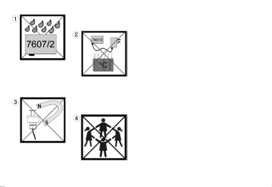
Mount control unit 7607/2 in dry and well ventilated
locations only ! (1)
Do not mount in the vicinity of heat sources (2);
ambient temperature max. 35° Celsius (95° F).
Do not situate magnetic pane cleaners or other
magnets in the vicinity of the sensor, as otherwise
functional failure is possible; keep a distance of at
least 20 cm (7.8 in.) (3).
Prior to initial operation, please check whether the
operating voltage corresponds to the mains voltage
available.
Remove the mains plug prior to any cleaning and
maintenance work. Do not repair a damaged mains
cable yourself, but have the unit repaired.
Do not operate the Water Level Alarm unattended.
This device is suitable for users (including children)
with limited physical, sensorial or mental abilities or
without any experience or previous knowledge only,
if a suitable supervision or detailed instructions
on the operation of the device is assured by a
responsible person. Please make sure that children
do not play with the device(4).
Sécurité d’utilisation
N’utilisez Water Level Alarm qu’en aquarium, toute
utilisation hors habitation est interdite.
Positionnez le Controller en un endroit sec et bien aéré (1).
Ne positionnez pas les appareillages près d’une source
de chaleur (2), température max. +35°C.
An d’éviter tout défaut intempestif, n’approchez pas
de sources magnétiques ou d’aimants à algues à
moins de 20 cm des capteurs (3).
Avant toute mise en fonction, vériez la compatibilité
de l’alimentation avec le réseau électrique.
Pour tout entretien, déconnectez l’alimentation. Ne
réparez pas un câble endommagé mais renvoyez tout
l’appareil en réparation.
N’utilisez pas Water Level Alarm sans une surveillance
régulière.
Veuillez attentivement observer la notice d’utilisation.
Les utilisateurs (enfants inclus) ayant des limitations
physiques, sensorielles, psychiques, ne bénéciant pas
d’une expérience ou de connaissances sufsantes ne
peuvent utiliser cet appareil qu’avec le concours d’une
tierce personne responsable, assurant la surveillance
ou veillant à l’observation du mode d’emploi. Veuillez
vous assurer que les enfants ne puissent jouer avec
cet appareil (4).

10
Platzwahl für Steuergerät 7607/2
Wand muss trocken sein, Platz nicht über dem
Aquarium wählen! (1)
Vorhandene Kabellänge beachten, Verlängerung
nicht möglich!
Das Kabel (4) von der Schaltsteckdose zum
Steuergerät (3) kann im Steuergerät abgesteckt
werden. Gerät vor dem Öffnen vom Netz trennen.
Deckel abnehmen, dazu beide Schrauben auf
Gehäuserückseite lösen.
Kontrollleuchten müssen sichtbar sein!
Kabelanschlüsse so verlegen, dass kein
Wasser entlang laufen und in Steuergerät oder
Schaltsteckdose gelangen kann. Wasser soll
aber auch dann nicht an das Gerät oder Kabel
gelangen (2).

11
Location of control unit 7607/2
The wall has to be dry; do not select a position
above the aquarium ! (1)
Observe available cable length; an extension is not
possible !
The cable (4) from the switched socket outlet to the
control unit (3) can be disconnected from the control
unit. Disconnect the unit from the mains before
opening it. Remove the cover; for this purpose undo
the screws on the rear of the housing.
The indicators lamps have to be visible !
The cable connections have to be laid in such a way
that no water can run along them and get into the
control unit or the switched socket outlet (2).
Placement de la commande 7607/2
La surface doit être sèche, n’utilisez pas un
emplacement au-dessus de l’aquarium ! (1)
Observez la longueur des câbles, leur prolongation
est impossible !
Le câble (4) en provenance de la prise commandée
peut être déconnecté à l’intérieur du Controler
(3). Pour cela, débranchez l’appareil du réseau
électrique et ouvrez les deux vis à l’arrière du
boîtier.
Les diodes LED de contrôle doivent rester
visibles !
Disposez les câbles de capteurs de telle manière
à ce que l’eau ne puisse courir le long et pénétrer
dans le Controller ou dans la prise commandée. Le
Controller et les câbles ne doivent pas être exposés
à l’eau (2).

12
Befestigung
Zur Befestigung des Gerätes sind die beiliegenden
selbstklebenden Kunststoff-Hakenbänder
vorgesehen (3).
Untergrund muss fettfrei, sauber und glatt sein,
z.B. Kunststoffäche.
Bänder auf Gehäuse kleben, dazu Schutzfolie
abziehen und anpressen.
Danach die zweite Schutzfolie abziehen und Gerät
an gewünschter Stelle positionieren und andrücken,
dabei auf die Lage der Kabel achten.

13
Attachment
For attachment of the unit, please use the plastic
self-adhesive hook and loop strips enclosed (3).
The surface has to be free from grease, clean and
smooth, such as a plastic surface.
Stick the strips to the housing; for this purpose
remove the protective lm and press down.
Subsequently remove the second protective lm,
place the unit in the desired position and press
down, observing the position of the cables in the
process.
Fixation
Pour garantir sa xation, le boîtier de commande
est livré avec de solides bandes Velcro auto-
collantes (3).
La surface de collage doit être sèche et plane
Appliquez les deux bandes Velcro sur le boîtier de
l’appareil en décollant au préalable les protections
Déposez les protections suivantes, positionnez
l’appareil à l’endroit voulu en observant la longueur
des câbles puis pressez le tout sur la surface
destinée à la xation. Par la suite, les bandes
Velcro permettent un décrochage et un accrochage
facile.

14
7607/2 mit Unterschranklteranlagen
Genauere Hinweise nden Sie in den folgenden
Kapiteln.
A - Trockenlaufschutzsensor „ Too low“ unter
Normalwasserstand C schützt die Filteranlage bei
Ausfall der Wassernachfüllanlage.
B - Überlaufsensor „Too high“ im Aquarium schützt
z.B. vor verstopftem Ablauf.
C - Normaler Wasserstand im Filterbehälter.
D - Anschluss z.B. von Zulaufpumpe zum
Aquarium.
E - Zweiter Überlaufsensor „Too high“ im
Filterbehälter schützt bei Nichtabschalten der
Wassernachfüllanlage.
A B E

15
7607/2 in cabinet lter plant
For more detailed information, please refer to the
following chapters.
A - “Too low” run-dry protection sensor below
normal water level C protects the lter system
against failure of the water relling system.
B - “Too high” overow sensor in the aquarium
protects against a clogged drain, for example.
C - Normal water level in the lter tank.
D - Connection of recirculation pump to aquarium,
for example.
E - Second “Too high” overow sensor in the lter
tank provides protection, if the water relling system
is not switched off.
7607/2 en ltrations sous aquarium
Des informations complémentaires se trouvent
dans chapitres suivants.
A - Capteur contre la marche à sec «Too low»
placé en-dessous du niveau normal C, protège
l’installation contre le manque d’eau lors d’un
disfonctionnement du système de compensation
automatique.
B - Capteur anti-débordement «Too high» au
niveau de l’aquarium, protège d’une obstruction du
déversoir.
C - Niveau d’eau normal en ltration sous
aquarium.
D - Raccordement par exemple de la pompe de
reprise.
E - 2ème capteur anti-débordement «Too high» au
niveau de la ltration, protège contre les apports
d’eau intempestifs du système de compensation
automatique.

16
7607/2 mit Innenlteranlagen
Genauere Hinweise nden Sie in den folgenden
Kapiteln.
A - Trockenlaufschutzsensor „Too low“ im Aquarium
verwendbar, warnt und schützt so die Filteranlage
bei Ausfall der Wassernachfüllanlage.
B - Überlaufsensor „Too high“ im Aquarium,
schützt das Aquarium bei Nichtabschaltung der
Wassernachfüllanlage.
C - Normal- Wasserstand im Aquarium.
D - Anschluss z.B. Filterpumpe oder
Wasserstandsregler.
E - Zweiter Überlaufsensor wird nicht
verwendet und stillgelegt.
A B E

17
7607/2 in internal lter plants
For more detailed information, please refer to the
following chapters.
A - “Too low” run-dry protection sensor can be used
in the aquarium where it protects the lter system in
case of a failure of the water relling system.
B - “Too high” overow sensor aquarium provides
protection, if the water relling system is not
switched off.
C - Normal water level in the aquarium.
D - Connection of lter pump or water level regulator,
for example.
E - The second overow sensor is not used and is
shut down.
7607/2 en ltrations internes
Des informations complémentaires se trouvent
dans chapitres suivants.
A - Capteur contre la marche à sec «Too low»
placé dans l’aquarium, protège la ltration contre
le manque d’eau lors d’un disfonctionnement du
système de compensation automatique.
B - Capteur anti-débordement «Too high» placé
dans l’aquarium, protège du rajout intempestif d’eau
en provenance d’un système de compensation
défectueux.
C - Niveau d’eau normal dans l’aquarium.
D - Raccordement de la pompe de ltration ou du
système de compensation d’eau.
E - 2ème capteur anti-débordement non-utilisé et
neutralisé.

18
Platzwahl der Sensoren
Einsatz im Filterkasten oder an Aquarienwand:
Zugängliche Stelle wählen!
Im Unterschranklter nicht neben Wasserzulauf
oder Pumpenauslauf platzieren!
Direkte Lichtstrahlung durch HQI-Leuchten
vermeiden, starker Algenwuchs kann Funktion
stören!
Überlaufsensor hoch genug über max. Wasserstand
positionieren, so dass die Rückförderpumpe beim
Stopp keinen Überlauf-Alarm auslöst!
Einsatz im Filterkasten
Bei Unterschrankanlagen mit mehreren Kammern
oder eingetauchten Aquarienkammerltern
beachten: Trockenlaufsensor des Water Level
Alarm immer in letzte Filterkammer bei der
Rückförderpumpe einsetzen!
Optimale Arbeitsposition der Sensoren durch
Versuche bestimmen, dazu Schiebeteile verstellen.

19
Location for the sensors
Use in lter chamber or on tank wall:
Select accessible position !
Do not place next to water inlet or pump outlet in the
aquarium cabinet !
Avoid incidental light from HQI lamps; heavy growth
of algae may disturb the function!
Position the overow sensor high enough above
the maximum water level so that stopping the
recirculation pump does not cause an overow
alarm !
Use in lter chamber:
Please observe in case of aquarium cabinets with
several chambers or immerged aquarium chamber
lters: Always place the run-dry protection sensors
of the water level alarm in the last lter chamber
near the recirculation pump !
Determine the ideal operating position of the
sensors by trials; use sliding parts for this purpose.
Placement des capteurs
En ltrations sous aquarium ou sur paroi
d’aquarium:
Choisir un emplacement adapté !
En ltrations sous aquarium, évitez la proximité
d’une arrivée d’eau ou d’une sortie de pompe!
Evitez l’éclairement direct par HQI, une forte
croissance d’algues pouvant perturber le
fonctionnement.
Positionnez le capteur anti-débordement de telle
manière à ce qu’un arrêt de la pompe de reprise ne
puisse pas provoquer de défaut intempestif.
Filtrations sous aquarium
Dans les ltrations sous aquarium à plusieurs
compartiments ou ltrations par décantation, le
capteur contre la marche à sec du Water Level Alarm
doit toujours se situer dans le dernier compartiment
comportant la pompe de reprise!
Le positionnement optimal des capteurs nécessite
plusieurs essais. L’optimisation de ce réglage est
facilitée par la pièce coulissante supportant le
capteur.

20
Halterung an senkrechter Aquarienscheibe
(1) Halter vormontieren.
(2) Einstellen der Glasstärke (max.19mm) mit der
unteren Halteschraube.
(3) Klemmschraube anziehen. Auf festen Sitz
achten.
(4) Schiebeteil mit Halteplatte für Überlaufsensor
nach oben an gewünschte Stelle positionieren. Der
Stift an Halteplatte (5) muss in Richtung Sensor
zeigen.
(6) Schiebeteil mit Halteplatte für Trockenlaufsensor
unter Überlaufsensor positionieren. Achtung:
Schiebeteil (6) muss um 180° gedreht gegenüber
(4) auf die Schiene gesetzt werden.
Trockenlaufsensor „Too low“ mit Kabel nach oben
und Überlaufsensor „Too high“ mit Kabel nach unten
in Sensorhalter einführen, danach mit Haltemutter
verschrauben.
Zubehör
(7) Für Glasscheiben bis 34mm Dicke gibt es
längere Schrauben: 2 Schrauben M5 x 55mm, Art.
Nr. 3000.244
Table of contents
Popular Security System manuals by other brands

NTI
NTI ENVIROMUX-SRN-MTR-xxxV Series Installation instruction

Elkron
Elkron HP201 manual

DSC
DSC SYSTEM MASTER PC4000 instruction manual

Risco
Risco WiComm Reference manual

PCB Piezotronics
PCB Piezotronics IMI SENSORS Y683A101001 Installation and operating manual

Control Products
Control Products WA-1000 user manual