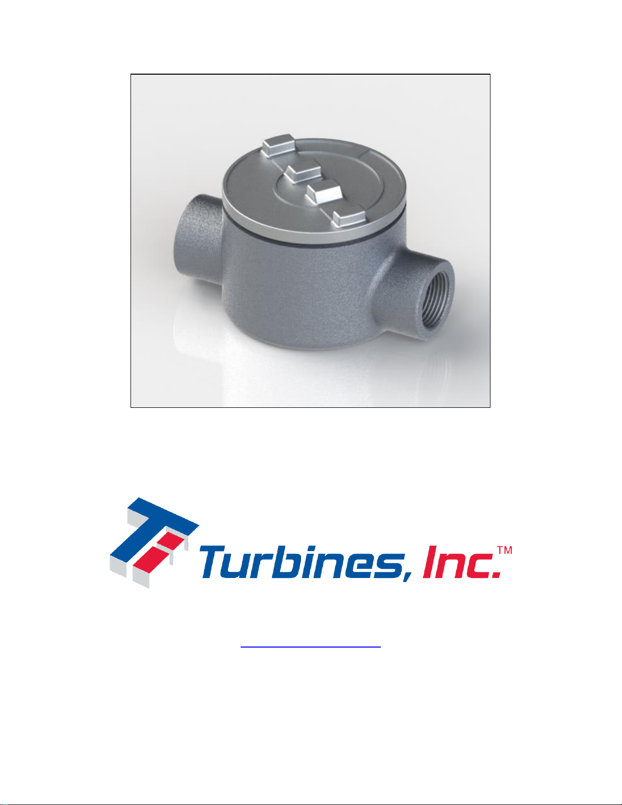
Turbines PT420 User manual

Model PT420
Frequency Converter
PO Box 933, 15935 US Hwy 303 N.
Altus, OK 73522-0933
1-800-809-1387
Seneca: 864-882-4544
http://turbinesincorporated.com
Copyright 2013-2017 Turbines Inc. All rights reserved.
Information contained herein is subject to change at any time without prior notice.

Notice
Proprietary Notice
The information contained in this publication is derived in part from proprietary data and trade secrets.
This information has been prepared for the expressed purpose of assisting operating and maintenance
personnel in the efficient use of the instrument described herein. Publication of this information does not
convey any rights to use or reproduce it or to use for any purpose other than in connection with the
installation, operation, and maintenance of the equipment described herein.
Copyright 2015
Printed in USA. All Rights Reserved.
SAFETY INSTRUCTIONS
The following instructions must be observed.
Every effort has been made to design and manufacture this instrument to be safe for its intended use.
A hazardous situation may occur if this instrument is not used for its intended purpose or is used
incorrectly. Please note operating instructions provided in this manual.
The instrument must be installed, operated, and maintained by personnel who have been properly
trained. Personnel must read and understand this manual prior to installation and/or operation of the
instrument.
The manufacturer assumes no liability for damage caused by incorrect use of the instrument or for
modifications or changes made to the instrument.
The safety of any system incorporating the equipment is the responsibility of the assembler of the
system.
Les instructions suivantes doivent être respectées.
Tous les efforts ont été faits pour concevoir et fabriquer cet instrument est sans danger pour son
utilisation prévue. Une situation dangereuse peut se produire si cet instrument n'est pas utilisé
conformément à sa destination ou est mal utilisé. S'il vous plaît respecter les instructions fournies
dans ce manuel.
L'appareil doit être installé, utilisé et entretenu par du personnel ayant reçu une formation adéquate.
Le personnel doit lire et comprendre ce manuel avant l'installation et / ou le fonctionnement de
l'instrument.
Le fabricant décline toute responsabilité pour les dommages causés par une utilisation incorrecte de
l'instrument ou de modifications ou de changements apportés à l'instrument.
La sécurité de tout système intégrant l'équipement est de la responsabilité de l'assembleur du
système.
Technical Improvements
Turbines Incorporated may modify the technical data herein without notice.

Turbines Incorporated
PT420 User Manual
PT420 User manual.docx
Table of Contents
Description ....................................................................................................................................................1
Features ...............................................................................................................................................1
Specifications................................................................................................................................................2
Dimensional ..................................................................................................................................................5
Wiring............................................................................................................................................................6
Wiring Guidelines......................................................................................................................................6
Maintenance and Service .........................................................................................................................6
Enclosure..................................................................................................................................................6
Connections..............................................................................................................................................6
Wiring examples .......................................................................................................................................8
Operation Overview ....................................................................................................................................13
Flow Calculations....................................................................................................................................13
Linearization............................................................................................................................................14
Units of Measure.....................................................................................................................................14
4-20mA Current Loop .............................................................................................................................14
Voltage Output........................................................................................................................................16
Pulse Output...........................................................................................................................................18
Reset.......................................................................................................................................................21
Power......................................................................................................................................................21
PT420 Configuration and Operation.......................................................................................................22

Turbines Incorporated
PT420 User Manual
PT420 User manual.docx
1
Description
The PT420 Frequency Converter is a microcontroller based rate/totalizer designed for both, Liquid and
Gas Applications. The unit has PC programming and monitoring capability through a RS-232/USB type
data link and it also offers the option to set the minimum and maximum flow rate thresholds through two
on board pairs of switches and LED indicators. The two selectable PT420 inputs accept sine and square
wave signals generated by passive and, respectively, active magnetic pickup coil probes. Computations
include calculation of liquid flowrate in Pulses per Second based on the turbine pulse rate and in Gallons
per Minute based on the predetermined turbine k-factor. An internal 20 point linearizer allows linearization
of typically non-linear turbines-flowrate curve and extends the range of repeatable points outside the
normal linear range. Outputs include 4-20mA Current Loop, Factored Pulse Output, Voltage Output and
RS-232 data link. Allow
Features
-2-20 point linearizer
-4-20mA Current Loop or DC external powered operation
-Pulse input supports sine and square type signals from pickup coils probes
-All features/configuration settings are field programmable through a hyperlink terminal window
implemented on a RS-232 connected PC or laptop
-Field programmable Minimum and maximum flowrate via two on board switches
-Flowrate monitoring and pulse totalizer through a hyperlink terminal window implemented on a
RS-232 connected laptop
-Concurrent multiple outputs include 4-20mA Current Loop, Factored Pulse and 0-5/10V Voltage
-Built-in test system for testing the functionality of the two on board LED’s
-Error reporting and warning system
-Non-resettable “Grand” totalizer

Turbines Incorporated
PT420 User Manual
PT420 User manual.docx
2
Specifications
Programming and Monitoring Options via PC Displayed Hyperlink Terminal Window
Flowrate Monitoring
6 digit when expressed in Pulses per Second
Decimal locations: 0.01 to 9999.99
6 digit when expressed in Gallons per Minute
Decimal locations: 0.01 to 9999.99
Accuracy: ±0.1% of reading value
Pulses and Gallons Totalizer
11 digit for pulse counting
Decimal locations: 0 to 99,999,999,999
Accuracy: ± 1 pulse
11 digit for gallons counting
Decimal locations: 0.001 to 9,999,999,999.9
Accuracy: ± 0.001Gallon to ±1Gallon, K factor dependent
Manual Programming Options
Field selectable of minimum and maximum flowrate via two on board switches
Programming error indicated by on board LEDs
Power Supply
4-20mA Loop powered
Maximum supply voltage: 36V
Operational supply voltage: 6.5V to 30 VDC
Maximum Current: 25mA
Reverse polarity protected
DC powered
Maximum supply voltage: 36 VDC
Operational supply voltage: 5.5V to 30 VDC (7V to 30V for 0/5V Voltage output option and
12V to 30V for 0/10V Voltage output option)
Maximum supply current: 3.9mA (Pulse output ON and no external loads attached)
Reverse polarity protected
K-Factor range
Pulses per Gallon: 0.00001 to 999,999
Signal Input (sine and square wave)
Frequency: 1Hz-10kHz
Impedance: 10k ohms
Sensitivity(Sine): 10mVpp-28Vpp
Sensitivity(Square): 3.6-28V (50% duty cycle)

Turbines Incorporated
PT420 User Manual
PT420 User manual.docx
3
Engineering Unit Conversions
Pre-programmed units: Gallons
Compensation
Linearizer table 2 to 20 points
Time Base
Rates can be displayed per second or minute
Outputs
Factored Pulse (based on input pulses or calculated Gallons)
Input frequency range: 1Hz to 10KHz
Pulse Output Divider: 0.01, 0.1, 1, 10, 100, 1000, & custom
Pulses width variable or fixed: 2, 5, 10, 50, 100, 250, 500ms, & custom
Accuracy: ±1 pulse
Pulses acquiring interval: 1 sec
Output update interval: 1 sec
Pulse shape: square wave, 50% duty cycle
Pulse amplitude: 5 to 30V, proportional to supply voltage
Minimum load resistance: 1KΩ
Short circuit protection and recovery
Factored Rate current (based on input pulses or calculated Gallons)
Input frequency range: 5Hz to 6KHz
Current range: 4 to 20mA
Accuracy: 0.1% of reading at 25°C , 0.25% over temperature
Response time: 0.2 sec min (at 5Hz input frequency)
Scalable low and high programmable
Current Loop error detect and shut down
Factored Rate voltage (based on input pulses or calculated Gallons)
Input frequency range: 5Hz to 6KHz
Voltage range: 0 to 5V or 0 to 10V
Accuracy: 0.25% of FSR at 25 °C, 0.5% over temperature
Accuracy (special order): 0.1% of FSR at 25 °C, 0.25% of FSR over temperature
Response time: 0.2 sec min (at 5Hz input frequency)
Minimum load resistance: 10KΩ
Scalable low and high programmable
Short circuit protection and recovery
DC Output Voltage
Maximum output voltage: 35V
Operational output voltage: 5V to 30V, proportional to supply voltage
Max Current: 20mA
Short circuit protection

Turbines Incorporated
PT420 User Manual
PT420 User manual.docx
4
Compliance
Pollution Degree: 2
Overvoltage Category: I
Altitude: 2000 m max
Environmental
Operating: -40 to 65°C (-40 to 150°F)
Storage: -40 to 85°C (-40 to 185°F)
Enclosure
Cast Aluminum (copper-free)
Epoxy Powder Coat
Enclosure rating NEMA 3, 4, 4X
Class I, Division 1 and 2, Groups B, C, D
Class II, Division 1 and 2, Groups E, F, G
Class 1, Zone 1 and 2, IIA, IIB
Other features
EEPROM parameter storage
Programming and monitoring via a PC displayed Hyperlink Terminal Window
Field programmable Minimum and Maximum flowrate via two on board switches
Secondary storage location for parameters and linearizer table

Turbines Incorporated
PT420 User Manual
PT420 User manual.docx
5
Dimensional

Turbines Incorporated
PT420 User Manual
PT420 User manual.docx
6
Wiring
All of the PT420 connections with the external devices are made through two removable connectors. To
access the connectors, remove the face cover of the unit and observe connectors TB1 and TB2 on the
PT420 circuit board. The wiring for monitoring and programming PT420 is made through J1 connector,
placed on the same circuit board.
Wiring Guidelines
Turbines Incorporated recommends the following practices be followed:
All wires connected to the unit should be shielded
To help avoid ground loops and unexpected behavior, it is recommended that the opposite end of
any cable shield is left unconnected (the end opposite the PT420)
Care should be taken to ensure no part of any wire is not fully inserted into a connector to avoid
shorting other circuitry on the mounting board
Shields should not cover more than one set of signal wires at a time
Supply wires should be 30AWG minim
Maintenance and Service
The only user serviceable parts of the PT420 are TB1, TB2 and J1 connectors. When servicing or
programming the PT420, take care when opening the cover of the unit that any internal signal or power
wires are not strained or pulled.
Enclosure
In order to maintain enclosure ratings the following torque specs must be followed:
Item
Torque
1” NPT fitting
2.5 turns past hand tight
Enclosure Cover
1/8-1/4 turn past hand tight
Connections
The connections are listed on the rear of the PT420 board. For clarification, the connections are shown
below for each one of the three PT420 connectors (see Figure 1).
TB1
1
SINE +/PULSE +
2
SINE –
3
+ Vcc_OUT
4
GRND/SHIELD
Where:
SINE + and SINE –represent the differential input from a passive magnetic pickup coil
PULSE + is the single input from an active magnetic pickup coil
+Vcc_OUT is the optional voltage output for supplying an active magnetic pickup coil

Turbines Incorporated
PT420 User Manual
PT420 User manual.docx
7
TB2
1
LOOP +/+Vcc_INPUT
2
LOOP –
3
VOUT
4
POUT
5
GND/SHIELD
Where:
LOOP + and LOOP –are the inputs for 4-20mA current loop
+ Vcc_INPUT is the single input for external DC supply
VOUT is the factored voltage output
POUT is the factored pulse output
Where:
RS232_CTS and RS232_RTS are RS232 control signals
RS232_TXD and RS232_RXD are RS232 data signals
+ 5V_RS232 is the 5Vcc voltage input from RS232/USB cable
Figure 1. PT420 Connection Diagram
J1
1
GND
2
RS232_CTS
3
+5V_RS232
4
RS232_TXD
5
RS232_RXD
6
RS232_RTS

Turbines Incorporated
PT420 User Manual
PT420 User manual.docx
8
Wiring examples
The PT420 supports connections with a variety of external devices: passive and active magnetic pickup
coils, Flow monitors and PC’s or laptops for bench or infield programming/monitoring.
The examples presented below illustrate a number of typical connecting configurations between PT420
and theses devices.
Turbine sensor
The turbine sensor provides the PT420 with a sinusoidal signal generated by a passive magnetic pickup
coil or square pulses generated by an active magnetic pickup coil supplied from an external DC power
supply or PT420.
The typical configurations used for connecting a Turbine sensor to PT420 are illustrated below.
Notes:
In order to reduce the electromagnetic interference it is recommended that a shielded cable be used to
connect the Turbine sensor with PT420, as it is illustrated in the figures below.
For IS version of the PT420 a IS certified magnetic pickup coil has to be employed.
Active magnetic pickup coil power has to be supplied by a Class 2 or Limited Energy Source in
accordance with CSA 61010-1-12
Fig 1. Passive magnetic pickup coil.
Fig 2. Active magnetic pickup coil supplied by an external DC power supply.
Turbine active sensor
This end of
shield is not
connected
PT420
1
2
3
4
Sine +/Pulse +
Sine –
+ Vcc_Out
Gnd/Shield
Connector TB1 (Input Signals)
DC power supply
Active
Magnetic
Pickup Coil
A
B
C
+
–
PT420
1
2
3
4
Sine +/Pulse +
Sine –
+ Vcc_Out
Gnd/Shield
Connector TB1 (Input Signals)
Turbine passive sensor
Passive
Magnetic
Pickup Coil
A
B
This end of
shield is not
connected

Turbines Incorporated
PT420 User Manual
PT420 User manual.docx
9
Fig 3. Active magnetic pickup coil supplied by PT420.
Flow monitor
PT420 is able to provide a Flow monitor with three types of signals: 4-20mA, 0-5/10V and square pulses,
all based on the flowrate of the liquid/gas passing through the pipe is attached to.
The typical configurations used for connecting a Flow monitor to PT420 are illustrated below.
Notes:
In order to reduce the electromagnetic interference it is recommended that a shielded cable be used to
connect the Flow monitor with PT420, as it is illustrated in the figures below.
Current Loop power to be supplied by a Class 2 or Limited Energy Source in accordance with CSA
61010-1-12
Fig 4. Flow monitor configured as a flow rater using PT420 4-20mA output signal. PT420 Pulse output
has to be disabled. The Flow monitor common has to be isolated from PT420 ground.
Flow monitor
common isolated
from PT420 ground
Flow monitor
This end of
shield is not
connected
PT420
Loop +/Vcc +
Vcc –
Loop –
Voltage In
Pulse In
Common
Terminal Connector
1
2
3
4
5
Loop +/+Vcc_Input
Loop –
Vout
Pout
Gnd/Shield
Connector TB2 (Output Signals)
PT420
Turbine active sensor
This end of
shield is not
connected
1
2
3
4
Sine +/Pulse +
Sine –
+ Vcc_Out
Gnd/Shield
Connector TB1 (Input Signals)
Active
Magnetic
Pickup Coil
A
B
C

Turbines Incorporated
PT420 User Manual
PT420 User manual.docx
10
Fig 5. Flow monitor, configured as a flow rater using PT420 4-20mA output signal, and a separate
Voltage indicator using 0-5/10V output signal. The Flow monitor common isolated from PT420 and
Voltage indicator ground. Pulse output disabled.
Fig 6. Flow monitor configured as a flow rater using PT420 0-5/10V output signal. PT420 placed at a
short distance from the Flow monitor
Fig 7. Flow monitor configured as a flow rater using PT420 0-5/10V output signal. PT420 placed at a long
distance from the Flow monitor.
Flow monitor
This end of
shield is not
connected
PT420
Loop +/Vcc +
Vcc –
Loop –
Voltage In
Pulse In
Common
Terminal Connector
1
2
3
4
5
Loop +/+Vcc_Input
Loop –
Vout
Pout
Gnd/Shield
Connector TB2 (Output Signals)
Flow monitor
This end of
shield is not
connected
PT420
Loop +/Vcc +
Vcc –
Loop –
Voltage In
Pulse In
Common
Terminal Connector
1
2
3
4
5
Loop +/+Vcc_Input
Loop –
Vout
Pout
Gnd/Shield
Connector TB2 (Output Signals)
Flow monitor common
isolated from PT420 and
Voltage indicator ground
Flow monitor
This end of
shield is not
connected
PT420
Loop +/Vcc +
Vcc –
Loop –
Voltage In
Pulse In
Common
Terminal Connector
Voltage indicator
This end of
shield is not
connected
1
2
3
4
5
Loop +/+Vcc_Input
Loop –
Vout
Pout
Gnd/Shield
Connector TB2 (Output Signals)
Voltage Readout
Device
+
–

Turbines Incorporated
PT420 User Manual
PT420 User manual.docx
11
Fig 8. Flow monitor configured as a totalizer using PT420 pulse output signal.
Fig 9. Flow monitor configured as a flow rater and totalizer using PT420 0-5/10V and, respectively, Pulse
output signals.
PC/laptop
PT420 is provided with an RS232 data link, allowing its programming and flow monitoring through a
hyperlink terminal window displayed on a PC/Laptop screen.
The wiring between PT420 and a PC/laptop is illustrated below.
Fig 10. PC/laptop configured as a hyperlink terminal using the PT420 RS232 data link. The connection
between the two devices is made via a RS232 to USB cable type TTL-232R-3V3.
Programming and
monitoring terminal
device
RS232
RS232 to USB cable type TTL-232R-3V3
RS232 to USB
Interface
PC/Laptop
USB
Port
PT420
1
2
3
4
5
6
Gnd
RS232_CTS
+5V_RS232
RS232_TXD
RS232_RXD
RS232_RTS
Connector J1 (RS232 Data Link)
Flow monitor
This end of
shield is not
connected
PT420
1
2
3
4
5
Loop +/+Vcc_Input
Loop –
Vout
Pout
Gnd/Shield
Connector TB2 (Output Signals)
Loop +/Vcc +
Vcc –
Loop –
Voltage In
Pulse In
Common
Terminal Connector
Flow monitor
This end of
shield is not
connected
Loop +/Vcc +
Vcc –
Loop –
Voltage In
Pulse In
Common
Terminal Connector
PT420
1
2
3
4
5
Loop +/+Vcc_Input
Loop –
Vout
Pout
Gnd/Shield
Connector TB2 (Output Signals)

Turbines Incorporated
PT420 User Manual
PT420 User manual.docx
12
Note:
To assure normal operation of the 4-20mA Current Loop when using the RS232 data link, the RS232 to
USB cable has to be attached to J1 connector after the correct voltage is supplied at the 4-20mA inputs of
PT420 (pins 1 and 2 of the TB2 connector).
Caution:
For an IS certified PT420 installed in a hazardous location, all field wiring must conform to wiring methods
for explosion-proof installations as defined by the National Electric Code in United States or by the
Canadian Electric Code in Canada. Other International, State and local wiring codes may also apply.

Turbines Incorporated
PT420 User Manual
PT420 User manual.docx
13
Operation Overview
This section details different aspects of the PT420 operation.
Flow Calculations
Calculation for uncompensated flow rate and the input frequency:
Q = 60 * F / K
F = Q * K / 60 where,
Q –Flowrate, [Gallon/Minute]
F –Input frequency coming from flowmeter, [Hz]
K –K factor, [Pulse/Gallon]
Calculation for uncompensated volume (total flow):
V = Nin / K where,
V –Volume, (total flow), [Gallon]
Nin –Total number of input pulses coming from flowmeter, [Pulse]
K –K factor, [Pulse/Gallon]
For exemplification couple cases are presented below.
Case 1:
Assuming the following:
F = 100 Hz
Q = 100 Gallons/Minute
K = 60 Pulses/Gallon
It results,
Q = 60 * 100 / 60 = 100 Gallons/Minute based on a input frequency of 100 Hz and a given K factor
F = 100 * 60 / 60 = 100 Hz based on a flowrate of 100 Gallons/Minute and a given K factor
Case 2:
Assuming that the following:
Nin = 1000 Pulses
K = 60 Pulses/Gallon
It results,
V = 1000 / 60 = 16.666 Gallons
Note:
Grand volume, (grand total flow), is calculated independently from volume, (total flow).

Turbines Incorporated
PT420 User Manual
PT420 User manual.docx
14
Linearization
Linearization, as it pertains to the PT420, is the selection and interpolation of a K-Factor from a table of
calibrated values based on frequency. Whenever a new frequency is detected, the unit will look up
adjacent frequency values in the linearizer table and calculate a K-Factor (using linear interpolation). If
the frequency value is below the lowest frequency in the table, then the linearizer uses the lowest point in
the table. If the frequency value is above the highest point in the table, then the linearizer continues to
use the K-Factor from the highest point in the table.
Units of Measure
All unit of measure calculations are based on the conversion of the desired unit of measure to the system
units of measure, in this case Gallons, calculated from the input pulses and based on a calibrated
average or linearized K-factor. The main units of measure are Gallons for volume, (total flow), and
Gallons/Minute for flowrate. Additionally PT420 can present information about the number of input pulses
and input frequency in Hz.
4-20mA Current Loop
PT420 has a 4-20mA Current Loop feature which provides an output current proportional with frequency/
flowrate and whose minimum and maximum limits represent a set of preprogrammed minimum and
maximum frequency/flowrate values within the range of the flowmeter. Typically, the minimum
programmed frequency/flowrate produce a 4mA output current and the maximum programmed
frequency/flowrate produces a 20mA output current.
A number of useful formulas for expressing the relationship between frequency/flowrate and 4-20mA
output current are presented below:
I = ((Imax –Imin) / (Fmax –Fmin)) * (F –Fmin) + Imin
I = ((Imax –Imin) / (Qmax –Qmin)) * (Q –Qmin) + Imin
F = ((Fmax –Fmin) / (Imax –Imin)) * (I –Imin) + Fmin
Q = ((Qmax –Qmin) / (Imax –Imin)) * (I –Imin) + Qmin where,
I –Output current, [mA]
F –Input frequency, [Hz]
Q –Flowrate, [Gallon/Minute]
Imin –Minimum output current, 4 [mA]
Imax –Maximum output current, 20 [mA]
Fmin –Minimum frequency, [Hz]
Fmax –Maximum frequency, [Hz]
Qmin –Minimum flowrate, [Gallon/Minute]
Qmax –Maximum flowrate, [Gallon/Minute]
For exemplification couple cases are presented below.
Case 1:
Assuming the following:
F = 2510 Hz
Imin = 4 mA
Imax = 20 mA
Fmin = 10 Hz
Fmax = 5010 Hz

Turbines Incorporated
PT420 User Manual
PT420 User manual.docx
15
It results that for the input frequency of 2510 Hz, and given frequency limits, the output current will be,
I = ((20 –4) / (5010 –10)) * (2510 –10) + 4 = 12 mA
Case 2:
Assuming the following:
Q = 2510 Gallons/Minute
Imin = 4 mA
Imax = 20 mA
Qmin = 10 Gallons/Minute
Qmax = 5010 Gallons/Minute
It results that for the flowrate of 2510 Gallons/Minute, and given flowrates limits, the output current will be,
I = ((20 –4) / (5010 –10)) * (2510 –10) + 4 = 12 mA
Case 3:
Assuming the following:
I = 12 mA
Imin = 4 mA
Imax = 20 mA
Fmin = 10 Hz
Fmax = 5010 Hz
It results that, for the given frequency limits, an output current of 12 mA indicates an input frequency of,
F = ((5010 –10) / (20 –4)) * (12 –4) + 10 = 2510 Hz
Case 4:
Assuming the following:
I = 12 mA
Imin = 4 mA
Imax = 20 mA
Qmin = 10 Gallons/Minute
Qmax = 5010 Gallons/Minute
It results that, for the given flowrate limits, an output current of 12 mA indicates a flowrate of,
Q = ((5010 –10) / (20 –4)) * (12 –4) + 10 = 2510 Gallons/Minute
Notes:
The 4-20mA Output current is capped for frequency/flowrate values outside their selected minimum and
maximum limits, as it is illustrated in the below diagram.
To assure normal operation of the 4-20mA Current Loop when using the RS232 data link, the RS232 to
USB cable has to be attached to J1 connector after the correct voltage is supplied at the 4-20mA inputs of
PT420 (pins 1 and 2 of the TB2 connector).

Turbines Incorporated
PT420 User Manual
PT420 User manual.docx
16
The 4-20mA Output current dependency of flowrate is also shown in the following diagram.
Fig 11. 4-20mA Output current versus flowrate
Voltage Output
Similar to 4-20mA feature PT420 provides an output voltage proportional with frequency/flowrate and
whose minimum and maximum limits represent a set of preprogrammed minimum and maximum
frequency/flowrate values. In this case, the minimum programmed frequency/flowrate will produce a 0V
output voltage while the maximum programmed frequency/flowrate will produce a selectable 5V or 10V
output voltage.
A number of useful formulas for expressing the relationship between frequency/flowrate and the voltage
output are presented below:
U = (Umax / (Fmax –Fmin)) * (F –Fmin)
U = (Umax / (Qmax –Qmin)) * (Q –Qmin)
F = ((Fmax –Fmin) / Umax)) * U + Fmin
Q = ((Qmax –Qmin) / Umax)) * U + Qmin where,
U –Output voltage [V]
F –Input frequency, [Hz]
Q –Flowrate, [Gallon/Minute]
Umax –Maximum output voltage, 5/10 [V]
Fmin –Minimum frequency, [Hz]
Fmax –Maximum frequency, [Hz]
Qmin –Minimum flowrate, [Gallon/Minute]
Qmax –Maximum flowrate, [Gallon/Minute]
For exemplification couple cases are presented below.
I
4-20mA Output current
Q
Qmin
Qmax
Imin, 4
[GPM]
Flowrate
[mA]
Imax, 20

Turbines Incorporated
PT420 User Manual
PT420 User manual.docx
17
Case 1:
Assuming the following:
F = 2510 Hz
Umax = 10 V
Fmin = 10 Hz
Fmax = 5010 Hz
It results that for an input frequency of 2510 Hz, and given frequency limits, the output voltage will be,
U = (10 / (5010 –10)) * (2510 –10) = 5 V
Case 2:
Assuming the following:
Q = 2510 Gallons/Minute
Umax = 10 V
Qmin = 10 Gallons/Minute
Qmax = 5010 Gallons/Minute
It results that for a flowrate of 2510 Gallons/Minute and given flowrates limits, the output voltage will be,
U = (10 / (5010 –10)) * (2510 –10) = 5 V
Case 3:
Assuming the following:
U = 5 V
Fmin = 10 Hz
Fmax = 5010 Hz
It results that, for the given frequency limits, the output voltage of 5 V indicates an input frequency of,
F = ((5010 –10) / 10) * 5 + 10 = 2510 Hz
Case 4:
Assuming the following:
U = 5 V
Qmin = 10 Gallons/Minute
Qmax = 5010 Gallons/Minute
It results that, for the given flowrate limits, the output voltage of 5 V indicates a flowrate of,
Q = ((5010 –10) / 10) * 5 + 10 = 2510 Gallons/Minute
Note:
The 0-5/10V Output voltage is capped for flowrate values outside their selected minimum and maximum
limits, as it is illustrated in the below diagram.
Table of contents
Popular Media Converter manuals by other brands

Transition Networks
Transition Networks J-CF-02 user guide

4ms Company
4ms Company Spectral Multiband Resonator user manual

Transition Networks
Transition Networks CFMFF4040-100 user guide

DEVA Broadcast
DEVA Broadcast SmartGen Micro Quick user guide

IFM
IFM E30406 installation instructions

Wisenet
Wisenet SPE-410 Quick guides