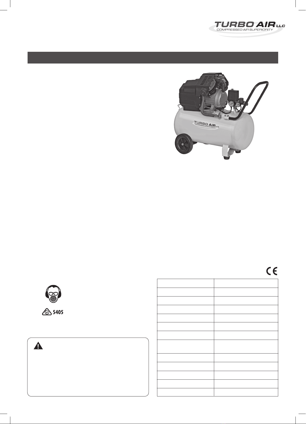
DIRECT DRIVE COMPRESSOR
3.
Congratulations on the purchase of your
TURBO AIR Direct Drive Compressor!
This product is manufactured to high quality standards
and will give you many years of service if you follow the
instructions for use and maintenance in this manual. If you
require any help with your product, whether it is a warranty
claim, spare part or user information, please visit www.
euroquip.co.nz rst and register your product online.
Once registered, please log a request online or call us on
0800 387 678. Your new Turbo Air compressor has been
manufactured under stringent AS/NZS Quality Standards to
meet superior performance criteria.
COMPRESSOR USAGE
This compressor has been designed for home workshop use and
ideal for the many tasks around home and in the shed that are
so much easier and quicker using the power and convenience of
compressed air.
ENVIRONMENT PROTECTION
Recycle unwanted materials instead of disposing of them as
waste. All tools, hoses and packaging should be sorted, taken to
the local recycling centre and disposed of in an environmentally
safe way.
DESCRIPTION OF SYMBOLS
The rating plate on your tool may show symbols. These represent
important information about the product or instruction on it’s use.
Wear hearing protection
Wear eye protection
Wear breathing protection
Conforms to relevant standards for
electromagnetic compatibility.
INTRODUCTION
SPECIFICATIONS:
• Powerful3.0HPInductionMotor
Designed for Aus / NZ conditions
• CastIronV-TwinPump
Super duty
• Large50LTankCapacity
Provides volume for high air demand applications
• 8Bar(115psi)
High pressure air delivery
• TwinOutletswithPressureRegulator
Includes 2 x quick release couplers
• HighCapacity300L/minFAD
(Free air delivery)
MODEL: TA3050
POWER: 3.0HP / 2250W
VOLTAGE: 230V~50Hz
NO LOAD SPEED: 2850rpm
CURRENT: 10A
MAX. OUTPUT: 360L/min, 12.7cfm
TANK CAPACITY: 50L
AIR OUTLET: 6.35mm (1/4”)
ARO Coupler x 2
CUT IN PRESSURE: 0.6Mpa (Factory Set)
MAX. OUTPUT PRESSURE: 0.8MPA (115psi)
FREE AIR DELIVERY: 300L/min
DIMENSIONS: 760 x 380 x 740mm (LxWxH)
WEIGHT: 37kg
CAUTION!
Carefully read through this entire instruction manual before
using your new compressor. Take special care to heed the
cautions and warnings. Your Iron Horse Compressor has
many features that will make your job faster and easier.
Safety, performance and dependability have been given top
priority in the development of this machine, making it easy
to maintain and operate.