Turf Equipment Z-SPRAY User manual

Operator’s Manual
For Serial Nos.
406,294,345 & Higher
Part No. 4504-922 Rev. A
Z-SPRAY
®

WARNING
CALIFORNIA
Proposition 65 Warning
The engine exhaust from this product
contains chemicals known to the State of
California to cause cancer, birth defects,
or other reproductive harm.
Battery posts, terminals, and related
accessories contain lead and lead
compounds, chemicals known to the State of
California to cause cancer and reproductive
harm. Wash hands after handling.
Use of this product may cause exposure
to chemicals known to the State of
California to cause cancer, birth defects,
or other reproductive harm.
Important: It is a violation of California Public
Resource Code Section 4442 or 4443 to use
or operate the engine on any forest-covered,
brush-covered, or grass-covered land unless the
engine is equipped with a spark arrester, as
in Section 4442, maintained in effective
working order or the engine is constructed,
equipped, and maintained for the prevention of
e.
To acquire a spark arrester for your machine, see your
Engine Service Dealer.
Please refer to the engine manufacturer's
information included with the machine.
The gross or net horsepower (or torque) of
this engine was laboratory rated by the engine
manufacturer in accordance with the Society
of Automotive Engineers (SAE) J1940 or J2723.
As ed to meet safety, emission, and
operating requirements, the actual engine
horsepower (or torque) on this class of machine
will be y lower.
©2020 Z Turf Equipment is part of the Exmark® family of
products
415 Industrial Row
Beatrice, NE 68310
2
Contact us at www.zturfequipment.com.
Printed in the USA
All Rights Reserved

Introduction
CONGRATULATIONSonthepurchaseofyour
Z-Sprayspreader-sprayer.Thisproducthasbeen
carefullydesignedandmanufacturedtogiveyou
amaximumamountofdependabilityandyearsof
trouble-freeoperation.
Thismanualcontainsoperating,maintenance,
adjustment,andsafetyinstructionsforyourZ-Spray
spreader-sprayer.
BEFOREOPERATINGYOURZ-SPRAY,
CAREFULLYREADTHISMANUALINITS
ENTIRETY.
Byfollowingtheoperating,maintenance,andsafety
instructions,youwillprolongthelifeofyourZ-Spray,
maintainitsmaximumefciency,andpromotesafe
operation.
Important:Tomaximizesafety,performance,
andproperoperationofthismachine,itis
essentialthatalloperatorscarefullyreadandfully
understandthecontentsoftheOperator’smanual
providedwiththeproduct.SafeoperationofZ
TurfEquipmentisessential.Failuretocomply
withtheoperatinginstructionsorreceiveproper
trainingmayresultininjury.
Gotohttps://www.zturfequipment.comfor
additionalsafeoperationinformation,suchas
safetytips,trainingmaterials,andOperator’s
manuals.
Ifadditionalinformationisneeded,orshould
yourequiretrainedmechanicservice,contactyour
authorizedZTurfEquipmentdealerordistributor.
AllZTurfEquipmentdealersanddistributorsare
keptinformedofthelatestservicemethods.Many
areequippedtoprovidepromptandefcientservice
intheeldorattheirservicestations.Theycarry
amplestockofservicepartsorcansecurethem
promptlyforyoufromthefactory.
AllZ-Spraypartsarethoroughlytestedandinspected
beforeleavingthefactory,however,attentionis
requiredonyourpartifyouaretoobtainthefullest
measureofsatisfactionandperformance.
Wheneveryouneedservice,genuineZ-Sprayparts,
oradditionalinformation,contactanAuthorized
ServiceDealerorZTurfEquipmentCustomer
Serviceandhavethemodelandserialnumbersof
yourproductready.
Figure1identiesthelocationofthemodelandserial
numbersontheproduct.Writethenumbersinthe
spaceprovided.
g313833
Figure1
1.Modelandserialnumberlocation
ModelNo.
SerialNo.
Forcompletewarrantydetails,see
https://www.zturfequipment.com.Youmay
alsocallus402-223-6375torequestawrittencopy
oftheproduct’swarranty.
3

Contents
Introduction...........................................................3
Safety.....................................................................5
SafetyAlertSymbol.........................................5
GeneralSafety.................................................5
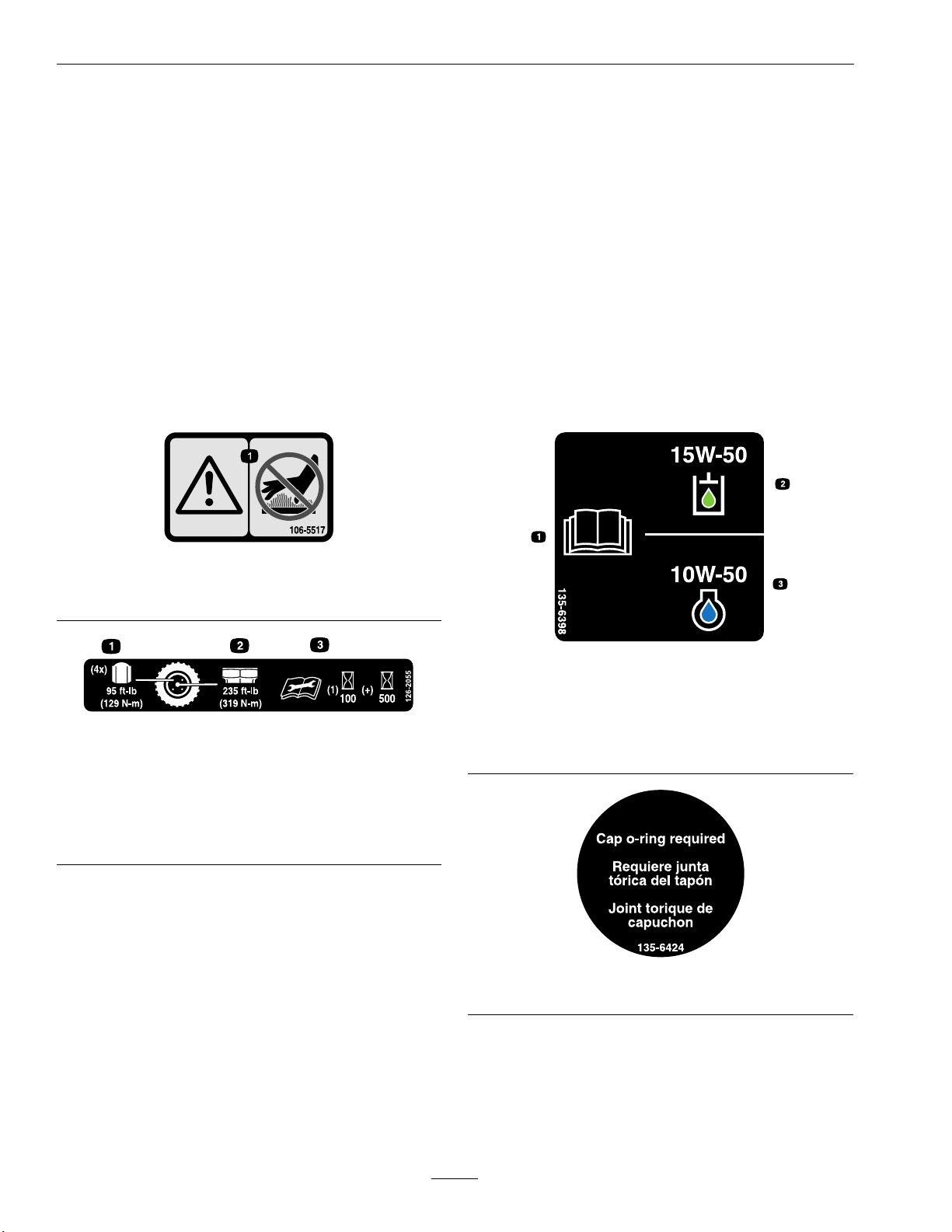
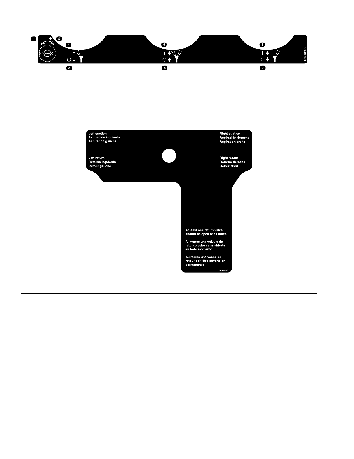
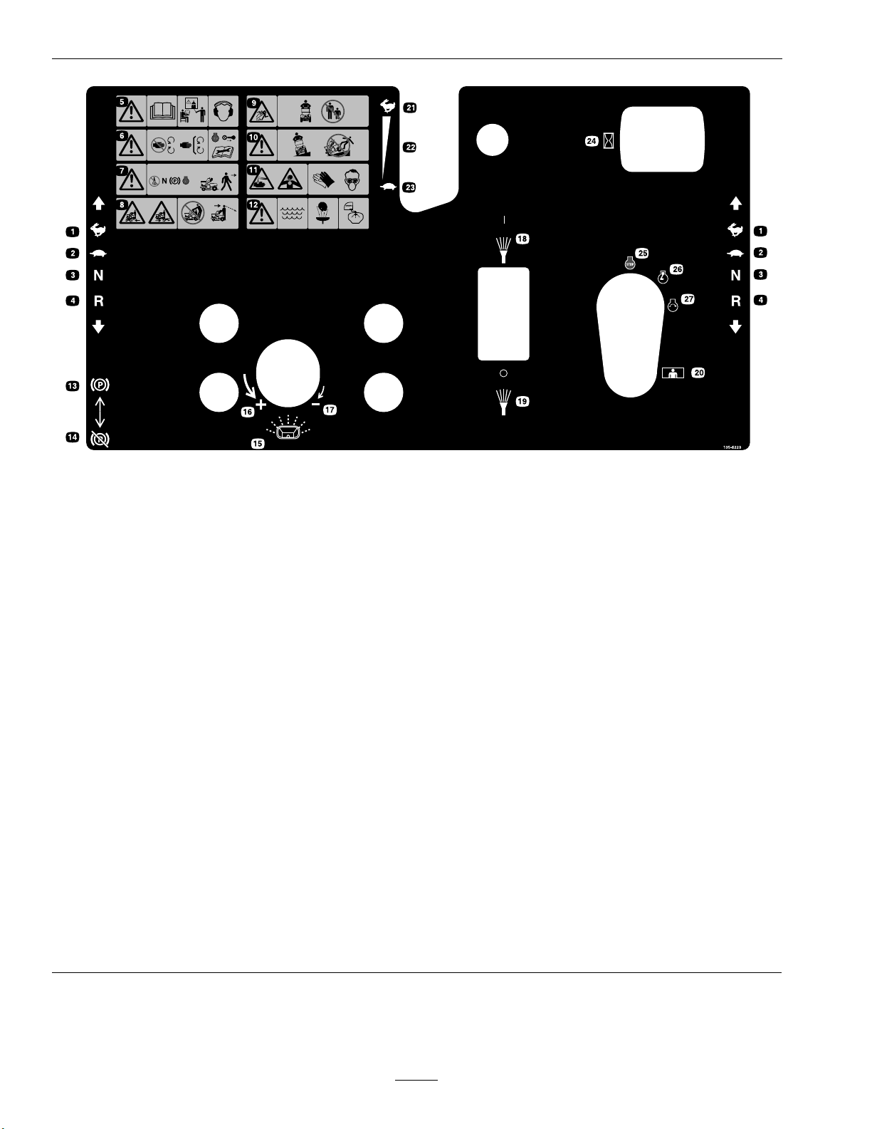
SafetyandInstructionalDecals.......................6
Specications........................................................12
Systems..........................................................12
Dimensions....................................................13
TorqueRequirements.....................................14
ProductOverview.................................................15
Operation..............................................................15
Controls.........................................................15
CasterWheelLockFootPedal........................20
BeforeOperation...........................................20
Pre-Start.........................................................21
OperatingInstructions...................................23
DuringOperationSafety.................................23
OperatingtheSprayer.....................................27
UsingtheSprayerTankShutoffValves............29
OperatingtheSpreader...................................32
SpreaderCalibration......................................34
AfterOperation..............................................40
Transporting..................................................40
Maintenance..........................................................42
MaintenanceSafety.............................................42
RecommendedMaintenanceSchedule(s)............43
PeriodicMaintenance........................................44
CheckEngineOilLevel..................................44
CheckBatteryCharge.....................................44
CheckSafetyInterlockSystem........................47
CheckforLooseHardware.............................48
ServiceAirCleaner.........................................48
ChangeEngineOil.........................................48
CheckHydraulicOilandTankLevel...............48
ChangeHydraulicSystemFilterand
Fluid..........................................................48
CheckTirePressures......................................49
CheckSpreaderSystem...................................50
CheckSprayerSystem.....................................50
CheckFuelFilterandTank.............................50
LubricateGreaseFittings................................51
CheckConditionofBelt.................................51
CheckSparkPlugs..........................................51
WheelMountScrewTorque
Specication...............................................51
Adjustments......................................................53
PumpDriveBeltTension................................53
AdjustingtheParkingBrake............................53
MotionControlLinkageAdjustment..............54
MotionControlTrackingAdjustment.............54
Cleaning............................................................55
CleanEngineandExhaustSystem
Area...........................................................55
RemoveEngineShroudsandClean
CoolingFins...............................................55
CleanDebrisFromMachine...........................55
WasteDisposal...............................................56
Storage..................................................................57
ExtendedorWinterStorage............................57
Troubleshooting....................................................58
Schematics............................................................60
CaliforniaProposition65Warning
Information...............................................62
4

Safety
Safety
Theintendeduseofthespreader-sprayerisforlawn
care.
SafetyAlertSymbol
ThisSafetyAlertSymbol(Figure2)isusedbothin
thismanualandonthemachinetoidentifyimportant
safetymessageswhichmustbefollowedtoavoid
accidents.
Thissymbolmeans:ATTENTION!BECOME
ALERT!YOURSAFETYISINVOLVED!
g000502
Figure2
SafetyAlertSymbol
Thesafetyalertsymbolappearsaboveinformation
whichalertsyoutounsafeactionsorsituations
andwillbefollowedbythewordDANGER,
WARNING,orCAUTION.
DANGER:Indicatesanimminentlyhazardous
situationwhich,ifnotavoided,Willresultindeathor
seriousinjury.
WARNING:Indicatesapotentiallyhazardous
situationwhich,ifnotavoided,Couldresultindeath
orseriousinjury.
CAUTION:Indicatesapotentiallyhazardous
situationwhich,ifnotavoided,Mayresultinminor
ormoderateinjury.
Thismanualusestwootherwordstohighlight
information.Importantcallsattentiontospecial
mechanicalinformationandNoteemphasizes
generalinformationworthyofspecialattention.
GeneralSafety
Thismachineiscapableofamputatinghandsand
feetandofthrowingobjects.ZTurfEquipment
designedandtestedthismachinetoofferreasonably
safeservice;however,failuretocomplywithsafety
instructionsmayresultininjuryordeath.
•Read,understand,andfollowallinstructionsand
warningsintheOperator’sManualandother
trainingmaterial,onthemachine,engine,and
attachments.Alloperatorsandmechanicsshould
betrained.Iftheoperator(s)ormechanic(s)
cannotreadthismanual,itistheowner’s
responsibilitytoexplainthismaterialtothem;
otherlanguagesmaybeavailableonourwebsite.
•Onlyallowtrained,responsible,andphysically
capableoperatorsthatarefamiliarwiththesafe
operation,operatorcontrols,andsafetysignsand
instructionstooperatethemachine.Neverlet
childrenoruntrainedpeopleoperateorservice
theequipment.Localregulationsmayrestrictthe
ageoftheoperator.
•AlwaysuseappropriatePersonalProtective
Equipment(PPE)toguardagainstcontactwith
chemicals.
•DoNotoperatethemachineneardrop-offs,
ditches,embankments,water,orotherhazards.
•DoNotputyourhandsorfeetnearmoving
componentsofthemachine.
•Neveroperatethemachinewithdamagedguards,
shields,orcovers.Alwayshavesafetyshields,
guards,switchesandotherdevicesinplaceandin
properworkingcondition.
•Stopthemachine,shutofftheengine,andremove
thekeybeforeservicing,fueling,orunclogging
themachine.
5

Safety
SafetyandInstructionalDecals
•Keepallsafetysignslegible.Removeallgrease,
dirtanddebrisfromsafetysignsandinstructional
labels.
•Replaceallworn,damaged,ormissingsafety
signs.
•Whenreplacementcomponentsareinstalled,be
surethatcurrentsafetysignsareafxedtothe
replacedcomponents.
•Ifanattachmentoraccessoryhasbeeninstalled,
makesurecurrentsafetysignsarevisible.
•Newsafetysignsmaybeobtainedfrom
yourauthorizedZTurfEquipmentdealeror
distributor.
•Safetysignsmaybeafxedbypeelingoffthe
backingtoexposetheadhesivesurface.Apply
onlytoaclean,drysurface.Smoothtoremove
anyairbubbles.
•Familiarizeyourselfwiththefollowingsafetysigns
andinstructionlabels.Theyarecriticaltothesafe
operationofyourZTurfEquipmentcommercial
spreader-sprayer.
decal106-5517
106-5517
1.Warning—donottouchthehotsurface.
decal126-2055
126-2055
1.Wheellugnuttorque95ft-lb(129N-m)(4x)
2.Wheelhubnuttorque235ft-lb(319N-m)
3.ReadandunderstandtheOperator’smanualbefore
performinganymaintenance,checktorqueafterrst
100hoursthenevery500hoursthereafter.
decal135-6398
135-6398
1.ReadtheOperator’s
Manual.
3.Onlyuseblue-colored
10W-50engineoil.
2.Onlyusegreen-colored
15W-50hydraulicuid.
decal135-6424
135-6424
6

Safety
decal135-6430
135-6430
1.Pressandholdthefoot
pedaltolockthecaster
wheelsinthestraight
position.
2.Releasethefootpedalto
unlockthecasterwheels
toallowturning.
decal135-6725
135-6725
1.Cutting/dismembermenthazard—stayawayfrom
movingparts.
decal135-6728
135-6728
1.Pressandholdfoot
buttontoturnonspray.
2.Releasefootbuttonto
shutoffspray.
decal142-3351
142-3351
1.SpreadOn-Pullhandle
up.
5.SpreadLock-Rotate
counterclockwiseto
unlock;rotateclockwise
tolock.
2.SpreadOff-Pushhandle
down
6.Deector-Pullknobupto
open
3.Spreadpattern
control-Pullhandle
upifheavyonleftside
7.Deector-Pushknob
downtoclose
4.Spreadpattern
control-Pushhandle
downifheavyonright
side
7

Safety
decal135-6285
135-6285
1.Waterpressure—decrease5.Centernozzlespray—off
2.Waterpressure—increase6.Centernozzlespray—on
3.Leftnozzlespray—off7.Rightnozzlespray—off
4.Leftnozzlespray—on8.Rightnozzlespray—on
decal135-6420
135-6420
8

Safety
decal142-3911
142-3911
1.Readtheinstructionsbeforeservicingorperforming
maintenance
5.Checktireandcasterwheelpressure(4locations)
2.Timeinterval6.Greaseidlerpivot;refertotheOperator'smanualfor
furtherinstructions
3.Checkengineoillevel7.Greasecasterpivots;refertotheOperator’smanualfor
furtherinstructions(2locations)
4.Checkhydraulicoillevel;refertotheOperator'smanual
forfurtherinstructions(3locations)
9

Safety
decal135-6223
135-6223
1.Fast15.Spreaderspeed
2.Slow16.Spreaderspeed—increase
3.Neutral17.Spreaderspeed—decrease
4.Reverse18.Spraypump—On
5.Warning—ReadtheOperator’sManual.DoNotoperate
thismachineunlessyouaretrained.Wearhearing
protection
19.Spraypump—Off
6.Warning—Stayawayfrommovingparts;keepallguards
inplace.Stopengineandremovekeybeforeadjusting,
servicing,orcleaning..
20.OperatorPresenceControl(OPC)
7.Warning—Disengagesprayercontrols,movedrivelever
toneutralposition,engageparkingbrake,andstopengine
beforeleavingtheoperator’sposition.
21.Throttle—fast
8.Crushing/dismembermenthazardofbystanders—DoNot
carrypassengers,lookforwardanddownwhenoperating
themachine,lookbehindanddownwhenreversing.
22.Continuousvariablesetting
9.Thrownobjecthazard—keepbystandersaway.23.Throttle—slow
10.Warning—operateacrossslopesnotupanddown.Loads
mayshiftonslopesorwhenturning.DoNotoperate
onwetslopes–useextremecautionwhenoperatingon
slopes.
24.Hourmeter
11.Causticliquid/chemicalburnandtoxicgasinhalation
hazard—wearhand,skin,eye,andrespiratoryprotection.
25.Engine—Off
12.Warning-Usefresh,cleanwater:
-forrst-aidwashing
-forrinsingthetank.
26.Engine—On
13.Parkbrake—On27.Engine—Start
14.Parkbrake—Off
10

Safety
4 MPH 5 MPH 3 MPH 4 MPH 5 MPH
30 VC 0.13 17 9.7 7.7 0.29 0.22 0.18
40 VC 0.15 19 11.1 8.9 0.34 0.26 0.20
50 VC 0.17 22 12.6 10.1 0.39 0.29 0.23
60 C 0.18 23 13.4 10.7 0.41 0.31 0.24
30 VC 0.17 22 12.6 10.1 0.39 0.29 0.23
40 VC 0.20 26 14.9 11.9 0.45 0.34 0.27
50 VC 0.22 28 16.3 13.1 0.50 0.37 0.30
60 VC 0.24 31 17.8 14.3 0.54 0.41 0.33
30 VC 0.22 28 16.3 13.1 0.50 0.37 0.30
40 VC 0.25 32 18.6 14.9 0.57 0.43 0.34
50 VC 0.28 36 21 16.6 0.63 0.48 0.38
60 VC 0.31 40 23 18.4 0.70 0.53 0.42
30 XC 0.26 33 19.3 15.4 0.59 0.44 0.35
40 VC 0.30 38 22 17.8 0.68 0.51 0.41
50 VC 0.34 44 25 20 0.77 0.58 0.46
30 XC 0.35 45 26 21 0.79 0.60 0.48
40 XC 0.40 51 30 24 0.91 0.68 0.54
50 VC 0.45 58 33 27 1.00 0.77 0.61
30 XC 0.43 55 32 26 0.97 0.73 0.58
40 XC 0.50 64 37 30 1.10 0.85 0.68
50 VC 0.56 72 42 33 1.30 0.95 0.76
30 XC 0.52 67 39 31 1.20 0.88 0.71
40 XC 0.60 77 45 36 1.40 1.00 0.82
50 VC 0.67 86 50 40 1.50 1.10 0.91
4 MPH 5 MPH 3 MPH 4 MPH 5 MPH
15 VC 0.61 78 45 36 1.40 1.00 0.83
20 VC 0.71 91 53 42 1.60 1.20 0.97
30 C 0.87 111 65 52 2.00 1.50 1.20
40 C 1.00 128 74 59 2.30 1.70 1.40
15 XC 0.92 118 68 55 2.10 1.60 1.30
20 XC 1.06 136 79 63 2.40 1.80 1.40
30 VC 1.30 166 97 77 2.90 2.20 1.80
40 C 1.50 192 111 89 3.40 2.60 2.00
*NOTE: Always double check your application rates.
Tabulations are based on spraying water at 70˚ F (21˚ C) Coarse Very Coarse Extremely Coarse
117-5839
HIGH VOLUME SPRAY CHART (XRC TIPS)
Drop
Size
CAPACITY
ONE NOZZLE
IN GPM
CAPACITY
ONE NOZZLE
IN OZ./MIN
__HIGH VOLUME SPRAYING (SPACING)__
/\ 20" /\
GPA
GALLONS PER 1,000 SQ. FT.
PSI
Drop
Size
CAPACITY
ONE
NOZZLE
IN GPM
CAPACITY
ONE
NOZZLE
IN
OZ./MIN
_______ SPACING________
/\ 20" /\
GPA
142-3307
GALLONS PER 1,000 SQ. FT.
142-3306
142-3308
142-3309
142-3310
142-3311
142-3312
*Grey tips are to be used ONLY the 4 tip booms*
PSI
135-8413
At 15 PSI (1 bar)
Pressure
At 60 PSI (4 bar)
Pressure
1 4.75
2 5.5
3 6.0
2 4.75
4 5.5
6 6.5
2 5
4 6.25
6 7.25
2) Begin to spread the product. As you are spreading you should be able to see the spread pattern in front of you.
Generally, all spreaders will tend to throw fertilizer heavy to the right. As you continue to spread, pull the Accuway
control towards you very slowly (small increments) until you begin to bring the spread pattern directly centered
in front of you.
3) Once you have the spread pattern centered, lock the Accuway cable in place. There should be no reason to reset
the Accuway for that product unless you see that the spread pattern has changed due to bumping the lever. If it has
changed slightly, simply re-adjust the pattern while you're spreading.
Accuway
Accuway balances the spread pattern, by shifting the product placement on the spinner. Placing the product on the
impeller close to the shaft or the center will cause the spread pattern to be heavier to the right as it rides the impeller
for a longer period. If the product is placed on the outer edge of the impeller, the spread pattern will be heavier to the
left (because the spinner is turning clockwise).
1) Start with the Accuway control cable all the way forward or in (this is home base).
Spreader / Sprayer Calibration:
Mixing of liquid or dry product should be in accordance to manufacturers labels. Remember this is designed
for low volume spraying so the mix will be more concentrated.
Remember that your machine is factory set to put down 1/3 gallon of liquid per 1,000 sq. ft (at 5MPH and
40PSI). For instance, some products call for 1.1 to 1.5 oz per 1,000 sq. ft. We would recommend using 1.3
(median value of 1.1 to 1.5). Since you are using a 1/3 gallon tip, you need to multiply by 3, then multiply that
amount by the number of gallons your put in your tank
1.3 (median value of 1.1 to 1.5) X 3 (1.3 gallon tip) X gallons of water needed. If you were filling a 30 gallon tank
your equation would look like this: 1.3 X 3 X 30 = 117 ounces in 30 gallons of water.
Approximate Granular Calibration
Throw fertilizer back to the center of tire tracks
5.0
6.0
6.5
Small Pellets
2
4
6
4.25
5.5
5.75
Product
Lbs. per
1,000 sq ft
Full Rate
Fine Pellets
1
2
3
4.75
5.25
5.5
Nitrogen Pellets Med.
Med. Pellets & Granules
Large Heavy Pellets
Mixed Fine Pellets
2
4
6
*Calibrated at 5 MPH
Fine
Mixed Fine
Small
Small/Med
Medium
Heavy
142-3313
decal142-3313
142-3313
11

Specications
Specications
Systems
Engine
•EngineSpecications:SeeyourEngineOwner’s
Manual
•EngineOilType:4-CyclePremiumEngineOil
•RPM:FullSpeed:3600±100RPM(NoLoad)
FuelSystem
•Capacity:5gal.(18.9L)
•FuelRecommendations:
–Forbestresults,useonlyclean,fresh,unleaded
gasolinewithanoctaneratingof87orhigher
((R+M)/2ratingmethod).
–Oxygenatedfuelwithupto10%ethanolor
15%MTBEbyvolumeisacceptable.
–DoNotuseethanolblendsofgasoline(such
asE15orE85)withmorethan10%ethanol
byvolume.Performanceproblemsand/or
enginedamagemayresultwhichmaynotbe
coveredunderwarranty.
–DoNotusegasolinecontainingmethanol.
–DoNotstorefueleitherinthefueltankor
fuelcontainersoverthewinterunlessafuel
stabilizerisused.
–DoNotaddoiltogasoline.
•FuelFilter:Infueltank
ElectricalSystem(ElectricStart)
•ChargingSystem:FlywheelAlternator
•ChargingCapacity:20amps
•BatteryType:BCIGroupU1
•BatteryVoltage:12Volt
•Polarity:NegativeGround
•Fuses:
–10ampmainfuse
–30ampsprayerfuse
–1ampspeedometerfuse
SafetyInterlockSystem
Enginewillnotstartunlesstheinterlockkeyis
installedintheOPCswitch.
OperatorControls
SteeringandMotionControl:
•Movingthesteeringcontrolfromsidetoside
controlsrightandlefttravel.
•Oneleverinthecenterofthesteeringcontrol,
controlsbothdrivewheelsformovingforwardor
reverse,stopping,andpowerturning.
•Motioncontrolleverautomaticallyreturnstothe
neutralpositionifreleased.
Transmission
•Tandemhydrogearvariabledisplacementhigh
efciencypumpscoupledwithtwohighefciency
Parkerwheeldrivemotors.
•HydraulicOil:Use15W-50.
•HydraulicOilCapacity:2.5qt(2.4L)
•Hydrauliclterisreplaceable,cartridgetype
•Speeds:
–0-8.0mph(12.9km/hr)forward.
–0-4.0mph(6km/hr)reverse.
•Drivewheelreleasevalveallowsmachinetobe
movedwhenengineisnotrunning.
WheelDriveSystem
DrivewheelsaredirectcoupledtoParkerwheeldrive
motorswith1.25inch(31.75mm)taperedshaft.
12

Specications
Tires&Wheels
Drive
Pneumatic(Air-Filled)
4246&52
Quantity22
TreadK358K500
Size20x8.00–820x10.50–8
PlyRating44
Pressure16-20psi
(110-138kPa)
16-20psi
(110-138kPa)
FrontCaster
Pneumatic(Air-Filled)
Quantity2
TreadRib
Size16x6.50–8
PlyRating4
Pressure16-20psi
(110-138kPa)
SprayerSystem
52InchModels:
•TankCapacity:60gallon(227L)(Twin30gallon
tanks)
•CenterNozzlesQuantity:3
•SprayWidth:
–CenterSectionandBothBooms:10ft(3m)
–CenterSectionOnly:6ft(1.8m)
–CenterSectionandOneBoom:8ft(2.4m)
–OnlyOneBoom:2ft(0.6m)
42and46InchModels:
•TankCapacity:30gallon(113.5L)(Twin15
gallontanks)
•CenterNozzlesQuantity:2
•SprayWidth:
–CenterSectionandBothBooms:8ft(2.4m)
–CenterSectionOnly:4ft(1.2m)
–CenterSectionandOneBoom:6ft(1.8m)
–OnlyOneBoom:2ft(0.6m)
•SprayPump:Remco5500SeriesDiaphragm
Pump-12VDC
SprayNozzles
HyproAirInjectedTips-Ceramic
TipColorMPHPressureGallons/1,000
sq.ft.
Yellow540psi.27(1/4)gallon
Lavender540psi.34(1/3)gallon
Red540psi.54(1/2)gallon
Brown550psi.76(3/4)gallon
Grey440psi1gallon
SprayWandNozzle
Adjustableowrateandspraypattern.
SpreaderSystem
•MaximumHopperCapacity:
–46and52InchModels:220lb(98.8kg)
–42InchModel:150lb(68kg)
•SpreaderMotor:Hydraulicmotor
•SpreaderWidth:Adjustablefrom3ft(0.9m)up
to25ft(7.6m).
Dimensions
OverallWidth:
52InchModel52inches(132cm)
46InchModel46inches(117cm)
42InchModel42inches(107cm)
OverallLength:
AllModels:73inches(185cm)
OverallHeight:
AllModels:50inches(127cm)
13

Specications
CurbWeight:
52InchModel52InchXL
Model
DryWeight950lb(431kg)960lb(435kg)
OnlyHopper
Full
1170lb(531kg)1180lb(535kg)
OnlySprayer
TanksFull
1450lb(658kg)1460lb(662kg)
Sprayand
HopperFull
withTwoBags
Granular
1770lb(803kg)1780lb(807kg
46InchModel42InchModel
DryWeight900lb(408kg)860lb(390kg)
OnlyHopper
Full
1120lb(508kg)1010lb(458kg)
OnlySprayer
TanksFull
1150lb(522kg)1110lb(563kg)
Sprayand
HopperFull
withTwoBags
Granular
1470lb(667kg)1360lb(617kg)
MaximumMachineWeight:
Operator+loadedmachine
52InchModel2000lb(907kg)
52InchXLModel2010lb(912kg)
46InchModel1700lb(771kg)
42InchModel1590lb(721kg)
Note:Overloadingthemachinewillshortenthelife
ofthetransmissionandvoidthewarranty.
TorqueRequirements
BoltLocationTorque
WheelHub235ft-lb(319N-m)
CrankshaftBolt35ft-lb(47N-m)
EngineMountingBolts132in-lb(15N-m)
LugNuts95ft-lb(129N-m)
WheelMotorMounting
Bolts
105ft-lb(142N-m)
FrontFrametoRear
FrameBolts
43ft-lb(58N-m)
EnginePlatetoRear
Frame
236in-lb(27N-m)
SprayNozzleMounting
Nuts
20in-lb(2N-m)
TowertoRearFrame263in-lb(30N-m)
PulleySetscrews156in-lb(18N-m)
14

Operation
ProductOverview
g313875
Figure3
1.Motioncontrollevers5.Hopper
2.Engine/Spreader–Sprayer
Controls
6.Spreaderimpeller
3.Spraywand7.Nozzles
4.Fuelcap8.Spraytank
Operation
Note:Determinetheleftandrightsidesofthe
machinefromthenormaloperatingposition.
Controls
Becomefamiliarwithallthecontrolsbeforestarting
theengineandoperatingthemachine.
MotionControlLevers
Themotioncontrollevers,locatedoneachsideofthe
topconsole,controltheforwardandreversemotion
ofthemachine.
Movingtheleversforwardorbackwardturns
thewheelonthesamesideforwardorreverse
respectively.Wheelspeedisproportionaltothe
amounttheleverismoved.
g313930
Figure4
1.LHMotioncontrollever5.Forward
2.RHMotioncontrollever6.Neutral
3.Frontreference/Speed
controlbar
7.Reverse
4.Frontofthemachine
Note:Ifthemotioncontrolleverdoesnotreturn
totheneutralpositionwhenreleased,contactan
AuthorizedServiceDealer.
15

Operation
ChokeControl
Locatedinthecenterofthecontrolconsole(see
Figure5).
Thechokeisusedtoaidinstartingacoldengine.
Pullinguponthechokewillputthechokeinthe
“ON”positionandpushingdownonthechokewill
putthechokeinthe“OFF”position.DoNotruna
warmenginewiththechokeinthe“ON”position.
g313931
Figure5
1.LHMotioncontrollever6.HourMeter
2.Frontreference/Speed
controlbar
7.RHMotioncontrollever
3.Throttle8.OperatorPresence
Control(OPC)lanyard
4.Choke9.Parkingbrake
5.Ignitionswitch
ThrottleControl
Locatedinthecenterofthecontrolconsole(see
Figure5).
Thethrottleisusedtocontrolenginespeed.Moving
thethrottleleverforwardwillincreaseenginespeed
andmovingthethrottlelevertotherearwilldecrease
enginespeed.Movingthethrottleforwardintothe
detentisfullthrottle.
ParkBrakeLever
Locatedontheleftsideofthecontroltower(see
Figure5).
Thebrakeleverengagesaparkingbrakeontothe
drivetires.
Toengage,pulltheleverupandforward.
Todisengagethebrake,pushtheleverbackand
down.
Whenparkingonasteepslope,thewheelsmustbe
chockedorblockedinadditiontothebrakebeing
engaged.Themachinemustbetieddownandbrake
engagedwhentransporting.
IgnitionSwitch
Locatedontherightsideofthecontrolconsole.
Theignitionswitchisusedtostartandstopthe
engine.Theswitchhasthreepositions“OFF”,“ON”
and“START”.Insertkeyintoswitchandrotate
clockwisetothe“ON”position.Rotateclockwiseto
thenextpositiontoengagethestarter(keymustbe
heldagainstspringpressureinthisposition).Allow
thekeytoreturntothe“ON”positionimmediately
aftertheenginestarts.
OperatorPresenceControl(OPC)
Lanyard
Locatedbelowtheignitionswitchonthecontrol
console.
ItisrecommendedtoattachtheOperatorPresence
Control(OPC)lanyardtotheoperator.Ifthelanyard
clawdisconnectsfromthestem,theenginewill
shutdown.
Tomakesurethelanyardisattachedproperlytothe
machine,pullupontheknobandthenpushthe
lanyardclawrmlyontothestem.
g314523
Figure6
1.Pullup3.Lanyardclaw
2.Stem
HourMeter
Locatedtotherightofthethrottle.
16

Operation
Thehourmeterisconnectedtoachargecircuit
installedintheengineblockanditrecordsthe
numberofhoursthattheenginehasrun.Ifignition
switchisleftonwithoutenginerunning,hourmeter
willnotrun.
GranularImpellerSpeedControl
Locatedontheleftsideofthecontrolconsole(see
Figure7).
Rotatetheknobcounterclockwisetostartthe
impellerandtoincreasethespeedandpatternwidth.
Rotatetheknobclockwisetodecreasespeed,pattern
width,andtoturntheimpelleroff.
1
2
3
5
6789
10
11
12
13
14
15
4
g314019
Figure7
1.Granularimpellerspeed
control
9.Spraypressuregauge
2.Spraysystemswitch10.Digitaldisplaygauge
3.Spraypressurecontrol
knob
11.SpreadOn/Off
4.Hosereelhandle12.Spreadpatterncontrol
5.Spraywandtriggerand
lock
13.Spreaddeectorlock
6.Leftnozzlespraylever14.Casterwheellockfoot
pedal
7.Centernozzlespray
lever
15.Spraypumpfootbutton
8.Rightnozzlespraylever
SpraySystemSwitch
Locatedtotheleftoftheignitionswitch.
Pushonthetopoftheswitchtoturnonthespray
systempumpaswellasthespotsprayfootswitch
ontheleftsideofthefootpan.Pushthebottom
oftheswitchtoturnthesprayer“OFF”.Oncethe
pumpisturnedon,thespraypressurecontrolknob
isturnedclockwisetoincreasepressureand/or
counter-clockwisetoreleasepressure(andcreate
agitationifthepumpison).Thepressurecanbe
readonthespraypressuregauge(decreasingpressure
fromgaugewillincreaseagitationinthetank).
SprayPumpFootButton
Locatedontheleftsideoftheoperatorplatform.
Pressandholdthefootbuttontoturnthesprayerto
“ON”.Releasethefootbuttontoturnthesprayer
“OFF”.
SprayPressureControlKnob
Locatedontheleftsideofthemachine.
Rotatetheknobclockwisetoincreasepressureand
counterclockwisetodecreasepressure.
Thepressurewillbedisplayedonthepressuregauge.
Oncethenozzlesareopened,therewillbeaslight
decreaseinpressure(adjustaccordingly).
SprayPressureGauge
Locatedtotherightofthespraylevers.
Displaysthespraypressurewhenthemachineis
spraying.
DigitalDisplayGauge
Locatedontherightsideoftheboommanifold.
RefertothedigitaldisplayUser’sManualforthe
displayinformation.
LeftNozzleSprayLever
Locatedtotherightofthespraywand.
Pushtheleverforwardtoturnontheleftnozzle
spray.Pulltheleverrearwardtoturnitoff.
CenterNozzleSprayLever
Locatedtotherightoftheleftnozzlespraylever.
17

Operation
Pushtheleverforwardtoturnonthecenternozzle
spray.Pulltheleverrearwardtoturnitoff.
RightNozzleSprayLever
Locatedtotherightofthecenternozzlespraylever.
Pushtheleverforwardtoturnontherightnozzle
spray.Pulltheleverrearwardtoturnitoff.
HoseReelHandle
Locatedontheleftspraytank.
Rotatethehandleclockwisetoreelthehosein.Rotate
thehandlecounterclockwisetoreleasethehose.
g314261
Figure8
1.Hosereelhandle3.Spraywandtriggerlock
2.Spraywandtrigger
SprayWandTrigger
Locatedonthebottomofthespraywandhandle.
Squeezethetriggertothehandleofthespraywand
toallowspray;releasethetriggertostop.
SprayWandTriggerLock
Locatedonthebottomofthespraywandhandle.
Squeezethetriggertothehandleofthespraywand
toallowspray.Pushthelocktriggerforwardtokeep
itintheopenowposition.Pullthelockbackto
releasethetrigger.
SprayWandFlowValve
Rotatetheknobcounterclockwisetoincreasethe
spraysystemoworclockwisetodecreaseowand
shutitoff.
Openingthevalveallowsliquidtothehosereelfor
sprayingoutofthehandspraywand.Whenhose
reelisnotinuse,besuretoturnvalveofftoprevent
boomtipsfromdripping.
g271228
Figure9
1.Valveclosedposition
SprayPumpValving
Locatedontherighttank.
Thevalvingoptionsallowproducttobepulledfrom
bothtankssimultaneouslyorindependently.
Rotatethelefthandlescounterclockwisetoturnon
thevalvesandclockwisetoturnitoff.
Rotatetherighthandlesclockwisetoturnonthe
valvesandcounterclockwisetoturnitoff.
g271204
Figure10
Pullliquidfromrighttankonly
1.Leftsuctionvalveoff3.Rightsuctionvalveon
2.Leftreturnvalveoff4.Rightreturnvalveon
18

Operation
g271205
Figure11
Transferringproductfromrighttanktoleft
SpreadOn/Off
Locatedontherightsideofthecontroltowerandis
thetopcable(seeFigure7)
Pullthehandleuptoturnonthespreaderimpeller.
Pushthehandledowntoshutoffthespreader
impeller.
SpreadPatternControl
Locatedontherightsideofthecontroltowerand
isthemiddlecable.
Thiscontrolisusedifthespreadpatternisskewedor
dispensingtoolight/heavytooneside.
Rotatethehandlecounterclockwise90degreesto
unlock.Ifpatternisheavytotheleft;pushthehandle
down;ifheavytotheright,pullthehandleup.Rotate
thehandleclockwise90degreestolock.
SpreadDeectorLock
Locatedontherightsideofthecontroltowerand
isthebottomcable.
Usethedeectorcontroltotemporarilystopor
deectgranularsawayfromsidewalks,parkinglots,
patios,oranywheregranularsarenotdesiredtobe
dischargedfromtheleftsideofthespreader.
Pushtheknobdowntolowerthedeectorand
temporarilydeectthegranulars.
Pulltheknobuptoraisethedeector.
g027373
Figure12
1.Fence3.Sidedeectorlowered
2.Flowers
RateGateDialandLinkage
Locatedatthefrontofthemachinebelowthe
spreaderhopper.
Therategatedialandlinkageisusedtosetthe
amountofmaterialtobedispensedfromthegranular
gate(seeFigure13).
g027033
Figure13
1.Slot–maximumposition2.Linkage
Withthegranulargateleverintheclosedposition,
turnthedialtotheappropriatesetting.Whenthe
granulargateleverispulledtotheopenposition,the
granulargatewillopentothesetposition.
Note:Theslot,aftersetting9onthedial,allowsthe
impellergatetobeopenedtothemaximumposition.
19

Operation
Thissettingcanbeusedfordrysand,icemelt,or
othermaterialsthataredifculttospread;itmay
alsobeusedforhoppercleanout(seeCleaningthe
Spreadersection).
CasterWheelLockFoot
Pedal
Locatedontherightsideoftheoperatorplatform
(seeFigure7).
Pressandholdthecasterwheellockfootpedalto
lockthecasterwheelsinthestraightposition.Release
thefootpedaltounlockthecasterwheelsandallow
themachinetofreelyturn.
g271157
Figure14
1.Casterpinlockingmechanism
BeforeOperation
BeforeOperationSafety
•Evaluatetheterraintodeterminewhataccessories
andattachmentsareneededtoproperlyand
safelyperformthejob.Onlyuseaccessoriesand
attachmentsapprovedbyZTurfEquipment.
•Inspecttheareawheretheequipmentistobe
usedandremoveallrocks,toys,sticks,wires,
bones,andotherforeignobjectswhichmaybe
contaminatedbychemicalsand/oraffectthe
stabilityofthemachine.
•Wearappropriateclothingincludingsafetyglasses,
substantialslip-resistantfootwear,andhearing
protection.Tiebacklonghairandavoidloose
clothingorjewelrywhichmaygettangledin
movingparts.
CAUTION
Thismachineproducessoundlevelsinexcess
of85dBAattheoperator’searandcancause
hearinglossthroughextendedperiodsof
exposure.
Wearhearingprotectionwhenoperatingthis
machine.
•DoNotoperatethemachinewhenpeople,
especiallychildren,orpetsareinthearea.Stop
themachineandattachment(s)ifanyoneenters
thearea.
•DoNotll,calibrate,orcleanthemachinewhen
people,especiallychildren,orpetsareinthearea.
•Checkallsprayercomponentsforwearandleaks
beforeapplyingpressuretothesystem.DoNot
useifleakingordamaged.
•Makesuretheoperatorplatformiscleanandfree
fromchemicalresidueanddebrisbuildup.
•Checkthattheoperatorpresencecontrols,
safetyswitches,andshieldsareattachedand
functioningproperly.DoNotoperateunlessthey
arefunctioningproperly.Frequentlycheckfor
wornordeterioratingcomponentsandreplace
themwiththemanufacturer’srecommendedparts
whennecessary.
20
Table of contents
Other Turf Equipment Spreader manuals
Popular Spreader manuals by other brands

SnowEx
SnowEx Precision Pro SP-1675 owner's manual

Redexim
Redexim RINK 1520 Operating and parts manual

Rauch
Rauch AXENT Series Operator's manual

Trynex
Trynex SnowEx SP-8550 Owner's/operator's manual

Western
Western Drop 250 Owner's manual and installation instructions

Agri-Fab
Agri-Fab PRO 125 owner's manual

U-Line
U-Line H-9932 manual

Trynex
Trynex SnowEx PWX-200 Onwer / Operator's Manual

Sulky Burel
Sulky Burel DX20 Original instructions

Trynex International
Trynex International SnowEx SL-80 Owner's/operator's manual

Enerpac
Enerpac FSM8 instruction sheet

EASTMAN
EASTMAN PACEMAKER Instruction Manual & Illustrated Parts List