Turnigy Fatboy 300A ESC User manual

The 300A ESC is one of the most powerful brushless speed controllers for rc model
airplanes. It is microprocessor controlled, and extremely low resistance. The unique
design, extreme powerful and optimum performance make the 300A ESC be the best
choice for big model airplanes. Meanwhile, it comes with following features:
Accurate current control and current limiting
Multi-point temperature protection
Smoothly start up with constant power output
Motor block-up protection
Very good cooling system, and easily to mount
With Data logger (optional version)
300A ESC Manuals
Ⅱ
Specifications
Voltage: 12V-65V (4s-15s Lipo)
Current: 300A (380A surge within 10 seconds)
No BEC
Size:19cm x 12cm x 4.9cm
Weight:850g
Auto detect Lipo cells
Fully Programmable LVC, cutoff voltage of each Lipo, current limiting, cutoff type, brake type, timing
advance, start type and governor mode.
The parameters with asterisk * behind are the preset parameters of 300A ESC in factory.
LVC 1 cell 2 cells 3 cells 4 cells* 5 cells ... 19 cells 20 cells
LVC/per cell 2.5v 2.6v 2.7v 2.8v 2.9v 3.0v * 3.1v 3.2v
Current limiting Sensitivity Standard* Insensitivity Close
Brake type Close* Soft Hard
Timing advance Auto* Low Middle High
Cutoff type Hard* Soft
Start type Soft Standard* Fast
Governor mode Auto* Low Hight
Auto
3.3v
Ⅰ
Features
Page1

Ш
Using the ESC
A. ESC picture
switch
ON OFF
Anti-sparkpin
Battery wire (+)
Battery wire (-)
Power LED
Receiver lead
Two small wires
* Battery wire (+): Connect positive battery wire of ESC to positive polarity of battery pack.
* Anti-spark pin: the pin is used to eliminate the generated sparks when connect ESC to battery.
* Power LED: The LED is red. It lights when ESC is powered, and extinguishes when disconnect
ESC from battery.
* Switch: The switch is used to switch on power or switch off power.
* Red LED: When ESC is powered, if this red LED lights, it reports no radio signal is detected. It
would extinguish when radio signal is recovered.
The Red LED would flash when current limiting of ESC function.
* Green LED: The green LED is flashing when ESC is working.
* Two small wires: The two small wires is used ONLY when connect ESC to Program box.
* Receiver lead: Plug the receiver lead to Channel 3 of receiver.
* Battery wire (-): Connect negative battery wire of ESC to negative polarity of battery pack.
Red LED
Green LED
Page2

B. Connect ESC to motor, receiver, battery pack
Preparation before connecting:
1. Solder three 8.0mm male golden bullet connectors to brushless motor;
2. Solder good conductive connectors to battery wires of ESC;
3. Prepare a UBEC or a separate receiver battery.
Page 3
C. Calibrate throttle travel of transmitter
Connecting steps:
- Switch ‘OFF’ the switch;
-Connect ESC to brushless motor;
-Plug the receiver lead of ESC to receiver (usually CH3);
-Connect UBEC or receiver battery to receiver;
-Very important: Connect battery negative polarity to ESC’s negative polarity, then put battery
positive wire connector touching on the Anti-spark pin for 5 seconds, and then quickly connect it to
ESC positive wire while it will reduce much sparks.
NOTE: In the following situations, it is required to calibrate the throttle range of
transmitter.
a. When it is first time to use a new speed controller.
b. When change a new TX or RX, or a set of new radio system.
C. When upgrade the ESC into a new version firmware.
When running at the calibrated max throttle, the RED LED on ESC will be blinking to
indicate the ESC is giving max throttle.

C. Calibrate throttle travel of transmitter
Fully program ESC by Program box
Ⅳ
Page 4
Push the joystick of transmitter to max throttle position, power on the transmitter.
2nd:
ON
OFF
3rd:
4th: After the following 2 beeps , immediately pull joystick to minimum throttle .
max throttle position (it will be 100% throttle point)
ON
OFF
ON
OFF
minimum throttle (it will be zero throttle point)
5th: 2 beeps emitting, calibrating is finished.
-Switch ‘OFF’ the switch;
-Connect ESC’s receiver lead to the female housing wire (black, red and white) of
‘Y’ cables in right polarity;
-Connect the two small wires (red and black) on ESC to the female housing wires
(black and red ) of ‘Y’ cables;
- Insert the male housing plug of ‘Y’ cables to program box in right polarity;
-Connect ESC to battery;
-Switch ‘ON’, the LCD panel will show the ESC’s name. It is ready to program the
ESC.
Female housing wires
(black, red, white)
Female housing wires
(black, red )
Program box
Battery
Y Cables Male housing wires
(black, red, white)

Press left arrow ‘←’ to get into
PARA SETTING menu
Up and down arrow‘↑’‘↓’ to select
2.6V 2.7V 3.0v* 3.3V
2.5V
Insensitivity Close
Parameter options
Update success
Fulcrum-300A
HIFEI ESC
Fulcrum-300A
PARA SETTING
Press left arrow ‘←’ again to get into set LVC of ESC.
Press down arrow ‘↓’ to back ESC’s parameter to default
1 cell
2 cells 3 cells 4 cells* ... 20 cells Auto
LVC
4 cells *
CUR LIMIT
Standard*
LVC/per cell
3.0V *
...
BRAKE TYPE
Close* Close* Soft Hard
TIMING
Auto* Auto* Low Middle High
CUTOFF TYPE
Hard* Hard* Soft
Sensitivity Standard*
START TYPE
Standard* Soft Fast
Standard*
GOVERNOR
Auto* Auto* High
Low
Press left arrow ‘←’ again to set LVC / per cell, right arrow ‘→’ back to last step
Press left arrow ‘←’ again to set Current Limiting, right arrow ‘→’ back to last step
Press left arrow ‘←’ again to set Brake type, right arrow ‘→’ back to last step
Press left arrow ‘←’ again to set Timing advance, right arrow ‘→’ back to last step
Press left arrow ‘←’ again to set Cutoff type, right arrow ‘→’ back to last step
Press left arrow ‘←’ again to set Start type, right arrow ‘→’ back to last step
Press left arrow ‘←’ again to set Governor mode, right arrow ‘→’ back to last step
- When finish the programming, switch ‘OFF’ the switch of ESC and disconnect ESC from program box.
- Connect ESC to brushless motor, receiver, and battery pack. Two power beeps emitting out, it is ready
to fly now!
- When ESC is powered, the power LED is lighting until ESC is powered off.
When ESC is working, the two fans are running to dissipate the thermal heat.
Fulcrum-300A
BACK TO DEFAULT
Press down arrow ‘↓’ to back
ESC parameters to default
Press ‘OK’, waiting… Update success
...
Press left arrow ‘←’ or right arrow ‘→’ to
back to PARA SETTING
Waiting ...
Press ‘OK’
Page5

Ⅴ
Using warnings
• It’s strongly recommended to calibrate the throttle travel of your transmitter when you fist use the
ESC or when use a new/different transmitter or receiver.
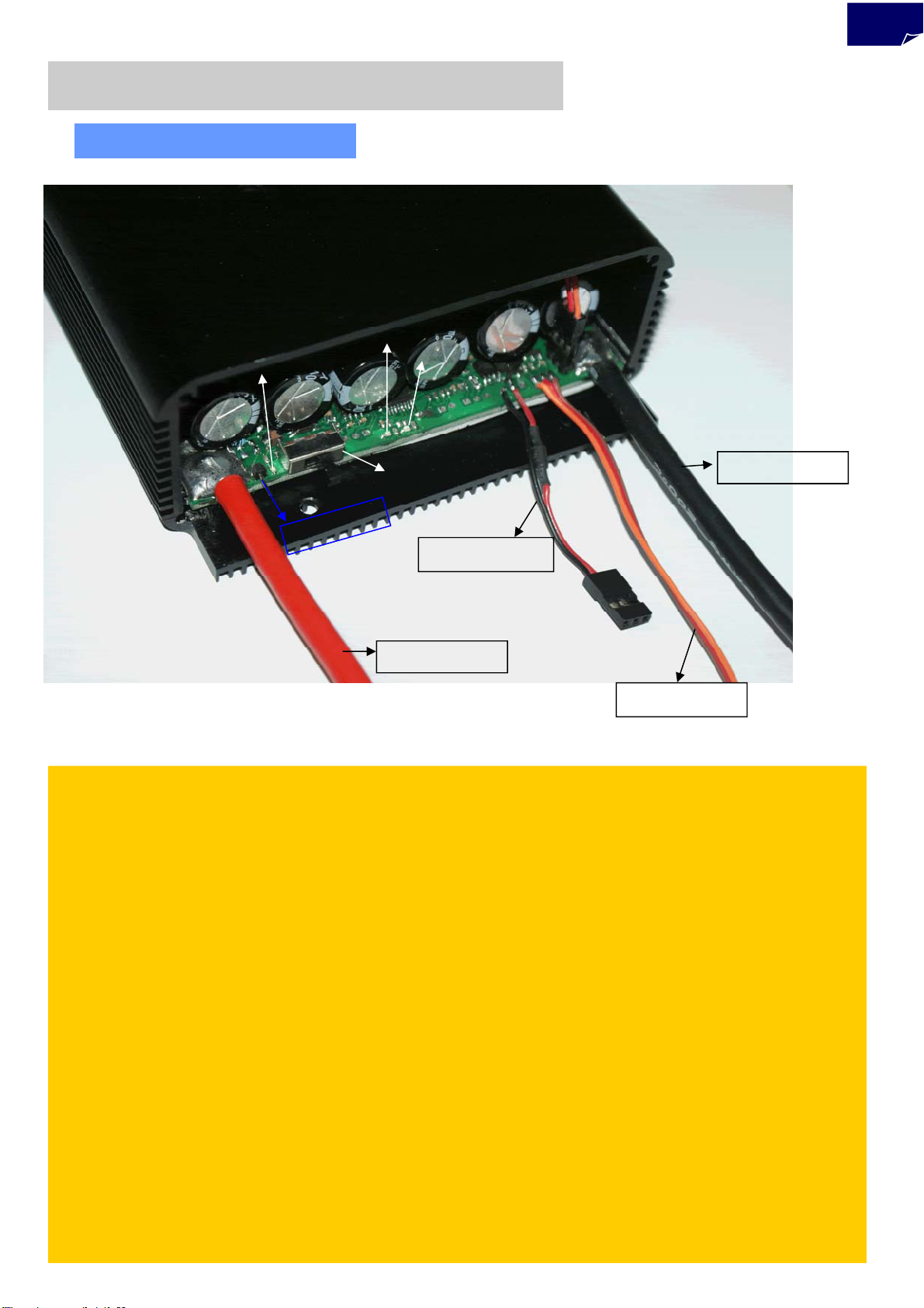
• When connecting the ESC to battery pack, please ensure the polarity is correct. Incorrect polarity
may cause permanent damage to the ESC and such damage is not covered by the WARRANTY.
• When you use the ESC, turn on the transmitter BEFORE powering on the receiver.
• When you finish the flying, power off the receiver BEFORE turning off the transmitter.
• It is very IMPORTANT to make sure the ESC is mounted in a good air flowing place for heat sinking.
• The limiting current is set to the ‘standard mode’ in factory. It is suitable for use in most
configurations. Only experienced technicians can adjust this programming.
• In Governor Mode, the brake is always disabled and the soft cutoff is always active.
• Do not play on or near water. Never allow water, moisture or any foreign object onto the PC board of
the ESC.
• Damage to the controller as a result of excessively high current is not covered by the manufacturer’s
WARRANTY.
• Never disconnect the battery pack while the motor is running, as this could cause damage to the
speed controller and/or motor.
• Connectors with low conductivity may cause erratic motor rotations or other unexpected movements.
• The controller will automatically cutoff output if the battery voltage drops below the programmed
cut-off voltage (factory preset at 12.0V). Correct LVC setting is very important to protect Li-polymer
cells from discharging and cause any permanent damage to cells.
• Allowing water, lubricants, moisture or other foreign objects inside the ESC will VOID the
WARRANTY. Exposure to CA glue or its fumes can cause damage and malfunction; this will also
VOID the WARRANTY.
NOTE !!!
This ESC is developed for application on RC electric model aircrafts. It is not
toys for children, so children must use it under wardship of adults.
Meanwhile, it is prohibited to any misuse in other applications. Manufacturers
and sellers disclaim responsibility for all loss result in misusing.
Page6
This manual suits for next models
1
Table of contents
Other Turnigy Controllers manuals
Popular Controllers manuals by other brands

Coster
Coster RTE 982 quick start guide

Texas Instruments
Texas Instruments UCC28600 manual

ESBE
ESBE CRD100 Series manual

MDT Technologies
MDT Technologies AKH-0400.01 operating instructions

A+ Corporation
A+ Corporation Sampling Experts Genie GHR product manual

Elmes Electronic
Elmes Electronic STM-2K quick start guide