Tuta D2 User manual

TUTA D2
GSM REMOTE CAMERA
USER MANUAL
UserManual V1.1

2
TUTA Series GSM Remote Camera
Thank you for purchasing this TUTA D2 device
All functions need to be supported by the GSM network and a SIM card
installed in TUTA D2 host.
This device is a remote controlled image-capturing device consisting of a GSM
wireless device and up to eight high quality analog wired CCTV cameras. The
TUTA D2 device intercepts the video signal captured by the linked wired camera,
converts video signal to images, and then sends it to your multimedia
messaging (MMS) enabled mobile phone with color display, or to an E-mail
address. The warning image(s) can be sent to the user’s mobile phone in a
timely manner, without the limited range of wired network. You can also opt to
view a slide of consecutive photos taken by the TUTA D2.
The built-in high-light infrared LED’s of the various CCTV cameras can allow
the device to capture clear images, even in dark environment or areas with
insufficient lighting.
The TUTA D2 can capture images according a pre-programmed remote Short
Message Service (SMS) commands. You can also send an SMS command to the
device in order to obtain real-time images.
The TUTA D2 is also compatible with up to 4 normal, easy to use wired sensors
which include wired infrared body-, door- and smoking sensors. You can also
opt to buy our TUTA D2 already assembled with any of these above mentioned
sensor types. As soon as the sensor activates the device, the preset user can
receive an alarm message via SMS, MMS or standard voice calls, according to
the pre-programmed settings.
However, the TUTA D2 can perform its duty well without any sensors. It has a
motion detection function and will detect any unauthorized entry into your
monitored areas and notify you via SMS, MMS, standard calls or E-mail.
The TUTA D2 has 2 output interfaces; they can support a siren or other alarm
device. If you connect a siren, when the TUTA D2 alarm, the siren will turned on
as well.
This brochure is for the TUTA D2 model.
Details on the functioning and advanced operation of this device are described in this
instruction manual.

3
CONTENT
SECURITYADVICE ...............................................................................................................5
EXCEPTION CLAUSE..........................................................................错误!未定义书签。
CHAPTER 1 FEATURES ANDACCESSORIES...................................................................... 7
1.1 Product Features ......................................................................................................... 7
1.2 Product Accessories .........................................................................................................8
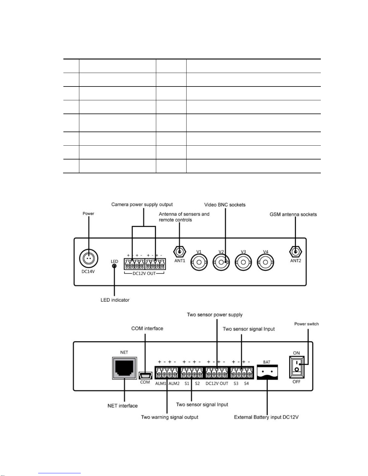
1.3 Host interface...................................................................................................................8
CHAPTER 2 TERMS EXPLANATION..................................................................................... 9
2.1 User Authorization Level..................................................................................................9
2.1.1 Super-Administrator number............................................................................................9
2.1.2 Administrator numbers.....................................................................................................9
2.1.3 Watchman numbers..........................................................................................................9
2.2 Arming the camera..........................................................................................................10
2.3 Arming the device/ Armed mode....................................................................................10
2.4 Arming the device manually...........................................................................................10
2.5 Arming the host...............................................................................................................10
2.6 Automatic alarm..............................................................................................................10
2.7 Bind the sensor with camera(s).......................................................................................11
2.8 Camera............................................................................................................................11
2.9 Capture image.................................................................................................................11
2.10 Disarming the device.......................................................................................................11
2.11 Host.................................................................................................................................11
2.12 Indicator Status Instructions of the host..........................................................................11
2.13 Motion detection.............................................................................................................11
2.14 Show alarm on computer ................................................................................................12
2.15 Settings............................................................................................................................12
2.16 Timing arms/disarms the camera ....................................................................................12
CHAPTER 3 NORMAL OPERATIONS ................................................................................. 12
3.1 Power On/Off..................................................................................................................12
3.2 Starting the device...........................................................................................................13
3.3 Change the password ......................................................................................................14
3.4 Name the cameras...........................................................................................................14
3.5 Sensor..............................................................................................................................15
3.5.1 Name a sensor................................................................................................................15
3.5.2 Bind a sensor with the camera(s) ...................................................................................16
3.5.2 Remove a sensor from the camera(s).............................................................................16
3.6 Add or remove administrator number.............................................................................17
3.6.1 Add an administrator number.........................................................................................17
3.6.2 Remove an administrator number/ Remove bound camera ...........................................18
3.6.3 Check administrator number..........................................................................................19
3.7 Add or remove watchman number..................................................................................19

4
3.7.1 Add an watchman number..............................................................................................19
3.7.2 Remove a watchman number / bound camera or sensor................................................20
3.7.3 Check watchman number...............................................................................................22
3.8 Capturing image..............................................................................................................22
3.9 Arming the device - Manual ...........................................................................................23
3.10 Disarming the device - Manual.......................................................................................23
CHAPTER 4 ADVANCED OPERATIONS ............................................................................ 24
4.1 Network parameter settings.............................................................................................24
4.1.1 Choose network operator’s MMS parameter .................................................................25
4.1.2 Setting MMS center .......................................................................................................25
4.1.3 Setting APN parameters.................................................................................................26
4.2 Timing arm/disarm the camera .......................................................................................26
4.2.1 Available timing arm/disarm the camera........................................................................26
4.2.2 Set time period to arm/disarm the camera......................................................................27
4.2.3 Disable timing arm/disarms the camera.........................................................................28
4.3 Timing sends MMS images.............................................................................................28
4.3.1 Available timing sends MMS images.............................................................................29
4.3.2 Set time period to send MMS image..............................................................................29
4.3.3 Disable timing sends MMS image.................................................................................30
4.4 Image parameter setting..................................................................................................31
4.4.1 Setting the image size.....................................................................................................31
4.4.2 Image quantity when automatic alarm ...........................................................................31
4.5 Motion detection.............................................................................................................32
4.6 Change the Super-administrator number.........................................................................33
4.7 Reseting the device .........................................................................................................33
4.8 Check status ....................................................................................................................34
4.9 Getting Help....................................................................................................................35
4.9.1 Getting frequently used commands via SMS.................................................................35
4.9.2 Getting detailed instruction via MMS............................................................................35
4.10 Language version switch.................................................................................................36
CHAPTER 5 MAINTENANCE................................................................................................ 36
CHAPTER 6 GENERAL TROUBLESHOOTING.................................................................... 36
Appendix: SMS commands list...............................................................................................39

5
1. You must purchase a GSM SIM card (mobile phone card) from GSM
network service and install it in the TUTA D2 host. This SIM card
number is TUTA D2 device number on this brochure. The SIM card
needs to be activated with both MMS functions and caller ID functions.
Contact with GSM network service for support.
2. Change the default password at the beginning of the using this device.
Be sure to keep the password and SIM card phone number secret. Do
not disclose this information to anyone other than the authorized users
in order to ensure your safety.
SECURITY ADVICE
This product is a wireless signal transmission device. Keep it away from
electronic equipment likely to interfere with the wireless signals, in order to
avoid the disturbance of these signals.
Switch off your TUTA and mobile phone when entering areas marked
"Explosive", "Might explode", "Closed wireless transceiver devices" etc.
Do not throw this product in a fire, as this may cause the battery to explode.
This product should only be operated from 220V/50Hz or 110V/60Hz (US)
AC power sources and DC12V backup storage battery. The use of any other
types of power sources may damage the product.
Keep this product and its accessories out of the reach of the children.
EXCEPTION CLAUSE
1. We operate on a policy of continuous development. We reserve the right to make
changes and improvements to any of the products described in this document
without prior notice.
2. For the latest product information, please visit: http://www.CellTechAlarms.com
. We don’t guarantee this document for veracity, reliability or any content except
where regulated by law. This includes no guarantee for product suitability for a
particular use.
3. Use only this product according to the law. We take no responsibility for the illegal
use of this product.
4. We take no responsibility for any loss of data or income; or any special, incidental,
consequential or indirect damages howsoever caused.

6
5. The contents of this document are provided “as is”. Except as required by
applicable law, we offer no warranties of any kind, expressed or implied, including,
but not limited to the accuracy, reliability or contents of this document. We reserve
the right to revise this document or withdraw it at any time without prior notice.

7
CHAPTER 1 FEATURES AND ACCESSORIES
1.1 Product Features
This product uses a GSM SIM card. It can send multimedia messaging (MMS)
images to MMS enabled mobile phones. This allows users to check on the
monitored areas at any time and anywhere GSM/GPRS network coverage
and MMS service coverage is available.
This unit will support up to eight analog wired CCTV cameras, allowing
monitoring of multiple locations and from potentially multiple angles.
This unit supports up to four different types of wired sensors. Different
abnormal situations can be detected with corresponding detectors such as
-IR, -smoke, and -gas detectors.
Up to two output interfaces, support sirens or other alarm devices.
SMS message Remote control: Control and configure the camera with short
messages (SMS) commands from a mobile phone.
Double-mode alarm: The camera can send alarm messages via SMS and
MMS.
Fixed time monitor: The monitoring schedule can be set with multiple time
intervals.
Up to ten mobile phone numbers can be set to receive alarm messages.
Multiple warning phone numbers setting: A phone number can be set to
receive one or several cameras’ image. A camera can be set to send images
to one or several warning mobile phone via MMS.
The unit supports an external battery to insure operated normally in the event
of a power failure.
Motion detection: Detect and notify authorized users of any motion in the
monitored area(s).
Connect with computer to store images and alarm information: the on the
spot status of every camera can be checked with connected computer.
Downloadable user manual: This manual can be downloaded at any time via
SMS command.

8
1.2 Product Accessories
No. Description Quantity Remarks
1 TUTA D2 host 1pc
2 GSM antenna 1pc
3 Network cable 1pc
4 cable 6pcs Input/output cable for sensor, alarm device
connecting and camera power supply.
5 Management Software CD 1pc
6 User Manual 1pc
7 Installation Guide 1pc
1.3 Host interface

9
CHAPTER 2 EXPLANATION OF TERMS
2.1 User Authorization Level
There are three levels, each with a different authorization level, namely
Super-Administrator, Administrators and Watchmen. Every authorized user must
store his/her mobile number in the device’s memory in order to enable all the
functions on the TUTA. The mobile number which corresponding with three
authorization levels is respectively called Super-Administrator number,
Administrator numbers and Watchman numbers.
2.1.1 Super-Administrator number
Only one Super-Administrator number is allowed per TUTA D2 device. It has the
authority to add or remove the Administrator and Watchman numbers, change the
password and use all functions of TUTA D2 except receiving alarm information via
mobile phone.
2.1.2 Administrator numbers
The Administrator numbers are set by the Super-Administrator number. (See
Chapter 3.6 Add or remove administrator number). Administrator numbers have the
authority to request images from corresponding camera(s) and set the device via
SMS command.
2.1.3 Watchman numbers
Watchman numbers have the authority to receive alarm information and request
images from corresponding camera(s) via mobile phone.
Table 2.1 The difference in authority for three authorization levels:
User Type
Functions Super-
A
dministrator
number Administrator
number Watchman
numbers
Add/Remove authorized user;
change password YES NO NO
Automatic
Alarm
Receive SMS NO NO YES
Receive MMS NO NO YES
Get images by mobile phone YES YES YES

10
Name the camera(s) YES NO NO
Get work status, help and
instruction by sending SMS
command. YES YES NO
Set the device by SMS
command. YES YES NO
Add/remove sensor(s) YES NO NO
Language version switch YES NO NO
2.2 Arming the camera
When the camera is armed, its motion detector and corresponding sensor are all
activated. If the camera is triggered to make an alarm, it will send the alarm message
to the host. But the alarm message will be sent out only when the host is armed.
2.3 Arming the device/ Armed mode
When the device (including the host and cameras) is armed, it works in armed mode.
All connected sensors and motion detector are in working status. The host will send
alarm message via SMS, MMS upon sensor alarms or detection of any motion within
the monitoring area.
2.4 Arming the device manually
Arm the device (including the host or camera) by sending SMS commands or click
ARM button on the TUTA WIRELESS IMAGE MONITORING SYSTEM.
2.5 Arming the host
When the host is armed, if the connected camera is armed too, the host will send an
alarm message via SMS, MMS upon sensor alarm or detection of any motion within
the monitoring area. These alarm messages will be sent to the Watchman number
which corresponds with the alarm camera.
If the host is not armed, the host will not send an alarm message out even if the
connected camera is armed.
2.6 Automatic alarm
The device will make an automatic alarm only when the device is armed. When the
connected sensor alarms or any motion is detected within the monitored area, the
device will make an automatic alarm.
If the host is connected with a management computer which has installed the TUTA
WIRELESS IMAGE MONITORING SYSTEM, the computer will pop up to show the
automatic alarm information and store all the alarm images.

11
2.7 Bind the sensor with camera(s)
When a sensor binds with a camera, it’ll trigger the camera take image when it alarms.
A sensor can be bound with several cameras.
2.8 Camera
The camera is connected with the host. Each camera has a camera number which in
the range of 1-4. The number is corresponding with the “Video BNC sockets” number
on the host. The Super-Administrator number and Administrator numbers have
authority to name the camera.
2.9 Capture image
The authorized users can send an SMS command to the device to get the MMS
image.
2.10 Disarming the device
The host and the camera must be disarmed respectively.
When the host is disarmed, it will not send out any alarm message at all.
When a camera is disarmed, neither the bound sensor(s) nor motion detector of the
camera will alarm. But the sensor which is not bound to the camera will still trigger the
armed host, sending out an alarm SMS message.
2.11 Host
The host is the TUTA D2 host.
2.12 Indicator Status Instructions of the host
Color Action Status
Red Flash slowly Device initializing…
Flash quickly Sensor alarm or motion detection alarm.
Green Constant Light Testing cameras during initialization.
Armed status.
Flash slowly Disarmed status.
Flash quickly Processing data.
Orange Light 1 second Restarting…
Note: Slow flash 1 time every 1.6 seconds, quick flash 1 time every 0.4 seconds.
2.13 Motion detection
The motion detection feature is based on moving body technology. This allows the
device to compare sequential images and detect motion (a difference from one
picture to the next is registered as motion).

12
The motion detection feature only functions when the host and the camera are armed.
Arming the camera enables the motion detection system.
2.14 Show alarm on computer
In order to show alarm on computer which is connected with the device, the user must
install TUTA WIRELESS IMAGE MONITORING SYSTEM software on the computer.
When the device is set as working under ALARM mode via the computer system, the
connected sensors and motion detector will be activated. If the monitoring system
program is running, the host will send an alarm message (including images and other
alarm information) to the computer. The alarm will be shown on the computer screen
and it will also sound via the computer speaker. If the monitoring system program is
not running, the host will send the alarm message to authorized user mobile phone
according to preset operation procedures.
2.15 Settings
All the settings can be set or adjusted via SMS commands or TUTA WIRELESS
IMAGE MONITORING SYSTEM.
2.16 Timing arms/disarms the camera
If the user sets the timing arming of the camera sucessfully, the camera (not including
the host) will change its working mode to armed or disarmed automatically according
to the setting schedule.
CHAPTER 3 NORMAL OPERATIONS
About the SMS Command:
1. SMS command format: #code#content#. The “#” symbol must not be ignored
when typing an SMS command.
2. Spaces must not be included within the commands.
3. The maximum digits that are allows for the phone number is sixteen.
4. The device will reply via an SMS message to the user after it receives the SMS
command.
5. The host can be connected with a computer to control and configure as well. See
TUTA D2 WIRELESS IMAGE MONITORING SYSTEM User Manual for details.
3.1 Power On/Off
3.1.1 Power on

13
Operation Indicator light Status
Turn the host
power switch to
“On” position.
Wait for 5
seconds…
Orange light flashes one time;
Red light fast flashes five times;
Orange light flashes one time;
Turn off for 10 seconds;
Green light be on for 20 seconds;
Turn off for 30 seconds;
Green light flash slowly, or
green light be on constantly. The device is disarmed
The device is armed
3.1.2 Power off
Turn the power switch to “Off” position; unplug the power plug; power-down the
storage battery (if any).
3.2 Starting the device
Authority: Super-Administrator number.
Description:
If the device is being used for the first time, or the device has been reset, the
Super-Administrator number must be programmed into the host in order to
ensure proper activation.
Command:
The user (who will be the Super-Administrator user) must send the following
SMS command to the device in order to:
Start the device: #00# (1)
☺Successful SMS reply:
Welcome. Super administrator ID:*******. PW:888888. IP:***
Note:
The information returned in a successful SMS reply is used for logging onto the
TUTA WIRELESS IMAGE MONITORING SYSTEM. Be sure to keep the
information secret.
Failed SMS reply:
If another user tries to activate the device again, the device will send a notification
via SMS stating “Super admin number already exists.” If needed, it is necessary to
reset the device first (See chapter 4.7 Reseting the device) and then try again.

14
3.3 Change the password
Authority: Super-Administrator number.
Description:
In order to ensure your privacy and safety during the use of this device, change
the password once the device is being used. There is only one password. The
user can change it via SMS command or TUTAWIRELESS IMAGE MONITORING
SYSTEM.
Command:
The user must edit and send the following SMS command to the device in order
to:
Change the password: #04#oldpassword#newpassword#(2)
•The password should be a six-digit number.
•The default password is 888888.
☺Successful SMS reply:
Change super administrator password to:******.
Failed SMS reply:
If a user, other than the master user, attempts to change the password, a
notification message will be sent via SMS, stating: “Sorry, you are not authorized
to use this command.”
3.4 Name the cameras
Authority: Super-Administrator number.
Administrator number can name the cameras which have been bound
together with the Administrator number.
Description:
The user can name the camera in order to identify which camera sent out the
alarm information. The camera description will be contained in the SMS and MMS
alarm information.
Command:
The user must edit and send the following SMS command to the device in order
to:
Name the camera: #15#CameraNumber#CameraDescription#(3)

15
•CameraNumber should be one-digit number and in the range of 1-4. It should
correspond with the number of Video BNC socket on the host.
•CameraDescription’s character description composed of up to 20 characters.
CameraDescription can be either letters and/or numbers.
•For example: Send command #15#1#doorcam# to give a name of doorcam to
the No.1 camera.
☺Successful SMS reply:
Set camera description successfully.
3.5 Sensor
Description:
Any wired sensor which meets the technical requirements of the device, such as
an infrared body sensor, a door magnet, a smoke sensor etc. can be set as an
alarm sensor of the device.
3.5.1 Name a sensor
Authority: Super-Administrator number and Administrator number.
Description:
After connecting the sensor with the host, the user can name the sensor in order
to identify which sensor sends out the SMS alarm information. The sensor
description will be contained in the SMS alarm information.
Command:
The user must edit and send the following SMS command to the device in order
to:
Name the sensor: #05#SensorNumber#SensorDescription#(4)
•SensorNumber is in the range of “S1” to “S4”. It should be corresponding with
the number of Sensor Signal Input on the host.
•SensorDescription’s is up to fourteen characters. SensorDescription can be
either letters or numbers, but can not be purely numeric.
•For example: Send the command #05#S1#doorsensor# to give a name of
doorsensor to the fixed sensor which connecting with S1 interface on the host.
☺Successful SMS reply:

16
Set sensor description successfully.
Failed SMS reply:
If the sensor description is invalid (for example, it is all numeric), the device will
send a notification message via SMS stating “Invalid sensor description, please
rename the sensor.”
3.5.2 Bind a sensor with the camera(s)
Authority: Super-Administrator number and Administrator number.
Description:
After connecting a fixed sensor to the host and in order to trigger the camera(s) to
take a picture when the sensor alarms, it must be bound to the appropriate
camera(s). Then when the sensor alarms, the host will send out MMS alarm
messages as well as SMS message to the user(s).
Command:
The user must edit and send the following SMS command to the device in order
to:
Bind a sensor with the camera(s): (5)
#40#SensorNumber#CameraNumber#.... CameraNumber#
Bind a sensor with all camera(s): (6)
#40#SensorNumber#
•SensorNumber is in the range of “S1” to “S4”. It should be corresponding with
the number of Sensor Signal Input on the host. SensorNumber can be
replaced with SensorDescription.
•CameraNumber should be a one-digit number and in the range of “1” to “4”. It
should be the camera number which will be bound with the sensor. A sensor
can be bound with up to eight cameras. CameraNumber can be replaced with
CameraDescription.
☺Successful SMS reply:
The sensor * associate with camera *** successfully.
3.5.2 Remove a sensor from the camera(s)
Authority: Super-Administrator number and Administrator number.
Description:

17
After binding a sensor with a camera, in order to make the host only send out SMS
alarm information but no MMS image when the sensor alarms, it is necessary to
remove the sensor from the camera(s).
Command:
The user must edit and send the following SMS command to the device in order
to:
Remove a sensor from the bound camera(s): (7)
#41#SensorNumber#CameraNumber#.... CameraNumber#
Remove a sensor from all bound camera(s): (8)
#41#SensorNumber#
•SensorNumber is in the range of “S1” to “S4”. It is the corresponding number
of the Sensor Signal Input on the host. SensorNumber can be replaced with
SensorDescription.
•CameraNumber should be a one-digit number and in the range of “1” to “4”. It
is the camera number which is bound with the sensor. A sensor can be bound
with up to eight cameras. CameraNumber can be replaced with
CameraDescription.
☺Successful SMS reply:
Remove sensor ** from camera *(, camera*) successfully.
Remove all sensors from binding cameras.
3.6 Add or remove administrator number
3.6.1 Add an administrator number
Authority: Super-Administrator number.
Description:
Up to ten Administrator number can be added to the device. If an Administrator
number be bound with a camera, it’ll receive the image captured by the camera.
Command:
The user must edit and send the following SMS command to the device in order
to:
Add the Administrator number bound with the camera(s): (9)
#06# AdministratorNumber#CameraNumber#.... CameraNumber#

18
Add the Administrator number bound with all camera(s): (10)
#06# AdministratorNumber#
•AdministratorNumber should be the mobile number which is desired to act as
an Administrator number. The length of AdministratorNumber is in the range
of three to nineteen.
•CameraNumber should be a one-digit number and in the range of “1” to “4”. It
is the camera number which is bound with the AdministratorNumber. An
AdministratorNumber can be bound with up to eight cameras.
CameraNumber can be replaced with Camera Description.
☺Successful SMS reply:
Add Admin number******* successfully. Bind camera is***.
Failed SMS reply:
•If a user, other than the Super-Administrator number, attempts to use this
command, the device will reply ”Sorry, you are not authorized to use this
command.”
•If ten Administrator numbers are used on the device and the user attempts to
add another one, the device will reply “Administrator numbers list is full. Please
delete old number.”
3.6.2 Remove an administrator number/ Remove bound
camera
Authority: Super-Administrator number.
Description:
•If the user removes a bound camera from the Administrator number
successfully, the Administrator number will not receive any images captured
by the camera any more.
•If the user removes an Administrator number successfully, the mobile phone
would not be Administrator number of the device, and will not receive images
from all camera(s).
Command:
The user must edit and send the following SMS command to the device in order
to:
Remove the bound camera(s) from an Administrator number: (11)
#113#AdministratorNumber#CameraNumber#.... CameraNumber#

19
Remove an Administrator number: (12)
#113#AdministratorNumber#
Remove all Administrator number(s): (13)
#113#
•AdministratorNumber should be the mobile number which the user wants to
remove. The length of the AdministratorNumber is in the range of three to
nineteen.
•CameraNumber should be one digit number and in the range of “1” to “4”. It
should be the camera number which bound with the AdministratorNumber.
An AdministratorNumber can be bound with up to eight cameras.
CameraNumber can be replaced with Camera Description.
☺Successful SMS reply:
Remove the bound camera*** from Admin number *** successfully.
Failed SMS reply:
If the Administrator number is invalid, the device will send a notification message
via SMS stating “Invalid phone number, please check and try again.”
3.6.3 Check administrator number
Refer to Chapter 4.8. Check status.
3.7 Add or remove watchman number
3.7.1 Add an watchman number
Authority: Super-Administrator number.
Description:
•Up to ten Watchman numbers can be added to the device.
•If a Watchman number is to be bound with a camera, it’ll receive the image
captured by the camera. A Watchman number can be bound with up to eight
cameras.
•If a Watchman number is to be bound with a sensor, it’ll receive the alarm
information if the sensor alarms. AWatchman number can be bound with up to
four sensors.

20
Command: *******************************
The user must edit and send the following SMS command to the device in order
to:
Add the Watchman number bound with the camera(s) and sensor(s): (14)
#106#WatchmanNumber#CameraNumber#....CameraNumber#SensorNumber#..
..#SensorNumber#
Add the Watchman number bound with all camera(s): (15)
#106#WatchmanNumber#*#
Add the Watchman number bound with all sensor(s): (16)
#106#WatchmanNumber#S*#
Add the Watchman number bound with all camera(s) and sensor(s): (17)
#106#WatchmanNumber#
•WatchmanNumber should be the mobile number to be added as a Watchman
number. The length of WatchmanNumber is in the range of three to nineteen
digits.
•CameraNumber should be a one digit number and in the range of “1” to “4”. It
should be the camera number which will bind with the WatchmanNumber.
•Replace CameraNumber with * means all connected cameras.
•CameraNumber can be replaced with Camera Description.
•SensorNumber is in the range of “S1” to “S4”. It should be the sensor number
which will bind with the Watchman number.
•Replace SensorNumber with S* means all connected sensors.
•SensorNumber can be replaced with SensorDescription.
☺Successful SMS reply:
Bind watchman number ******* to camera ***, sensor:******
Failed SMS reply:
If ten Watchman numbers are used on the device and the user attempts to add
another one, the device will reply “Watchman numbers list is full. Please delete old
number.”
3.7.2 Remove a watchman number / bound camera or
sensor
Authority: Super-Administrator number.
Description:
Table of contents
Other Tuta Digital Camera manuals