X2
3Hrs
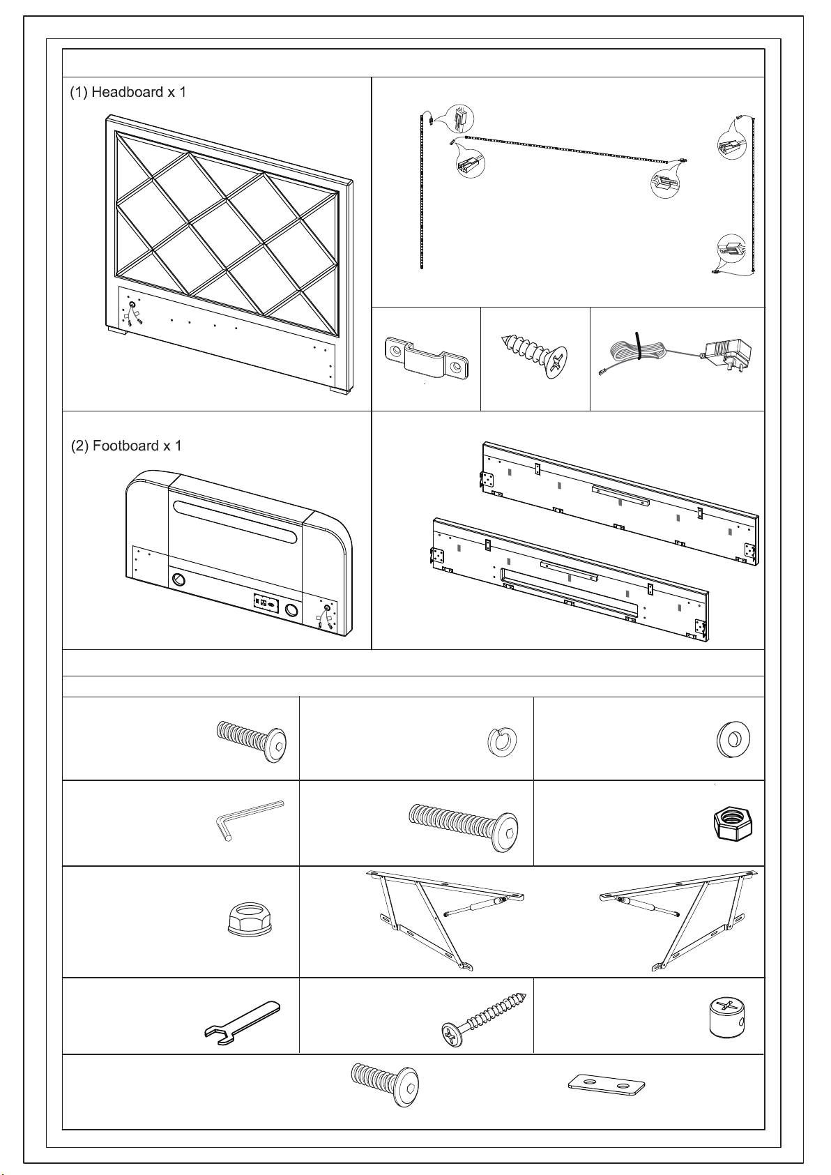
STANFORD SURROUND SOUND TV BED WITH LED
Double & King Super King
191027
OR
OR
An instructional video of the Operation of the Ottoman Lift Up system is available via YouTube using
the following address: https://youtu.be/hyq4zm7h_yU
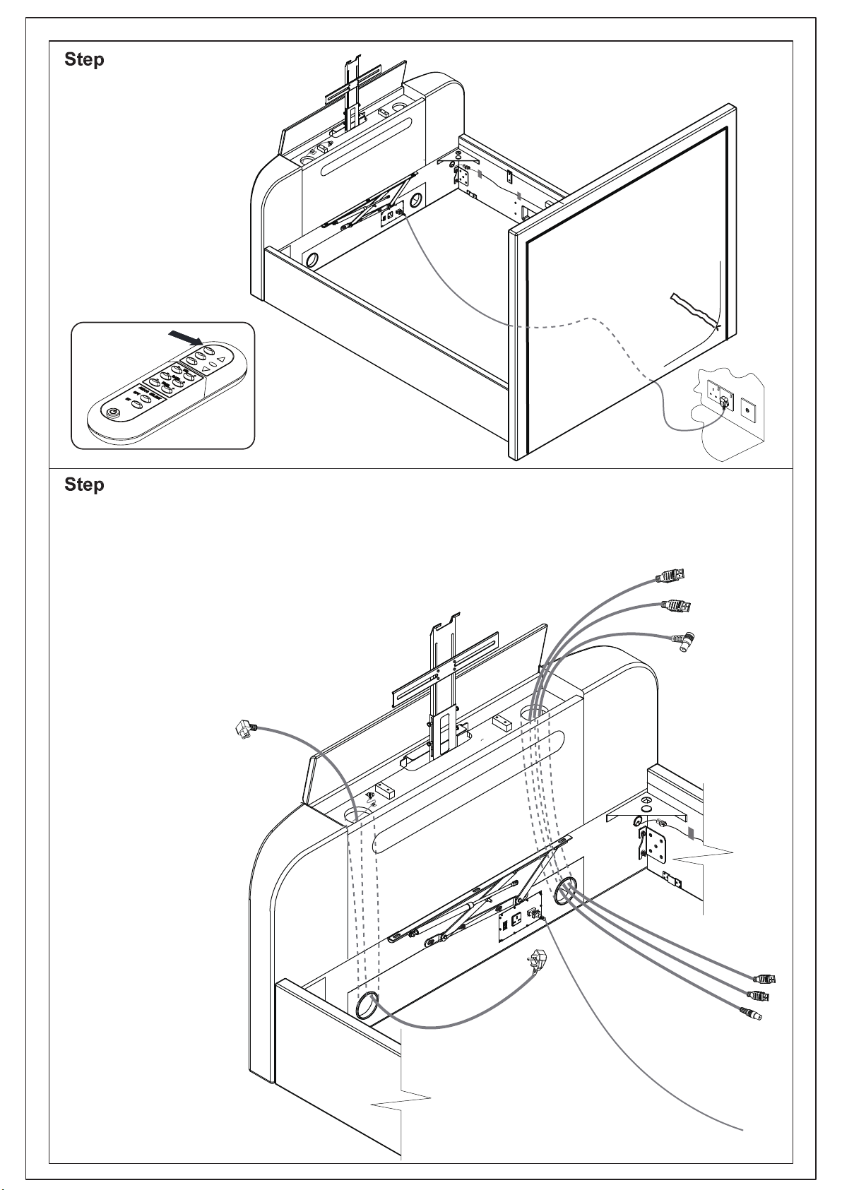
Press this button for 3 seconds.
Red Indicator light comes on.
BLUE
Lights when Bluetooth is Selected.
RED
Lights when System is
switched on and Ready to Use
SOUND SYSTEM CONTROL
ON / OFF BUTTON
PRESS BUTTON ON REMOTE CONTROL (RC) IN EITHER MODE.
i) SELECT BT; PLEASE RAISE VOLUME ON DEVICE TO HIGH LEVEL THEN ADJUST RC.
ii) SELECT OPTICAL; PLEASE MUTE TV SPEAKERS FOR BEST RESULTS.
ONE MAY OCCASIONALLY NEED TO ADJUST TV SETTINGS FOR EXTERNAL SPEAKERS,
THIS DEPENDS ON THE MAKE OF TV, PLEASE CHECK THE TV USER GUIDE. RESULTS.
ADJUST BASS- THIS BUTTON LIMITS LOWER FREQUENCIES OF THE SOUND
ADJUST BASS ATTENTUATION TO SUIT THE SOUND EFFECT YOU LIKE
ADJUST TREBLE - THIS BUTTON LIMITS HIGH FREQUENCIES OF THE SOUND
ADJUST TREBLE ATTENTUATION TO SUIT THE SOUND EFFECT YOU LIKE.
NOTE IF YOU REDUCE LEVEL OF THE HIGHER FREQUENCIES, SOUND VOLUME IS
REDUCED - THIS IS NORMAL.
SELECT BT (BLUETOOTH) - DEVICE INPUT - TO PAIR LOOK FOR "BT SPEAKER"
NOTE THAT IF TV IS IN THE UP POSITION AND SWITCHED ON, TV PICTURE IS STILL
SHOWING, IT IS NOT SWITCHED OFF WHEN BLUETOOTH IS SELECTED. TO REMOVE,
TURN OFF TV OR PRESS THE RC DOWN BUTTON TO LOWER TV TO REST POSITION
WHERE TV POWER IS DISCONNECTED AUTOMATICALLY - MUSIC CAN STILL PLAY.
SELECT OPT (OPTICAL)SOUND OUTPUT TO TV
WHEN FINISHED WATCHING TV, PRESS RC DOWN BUTTON TO SEND TV BACK DOWN TO
REST POSITION, TV SWITCHES OFF AUTOMATICALLY.
PRESS ON/OFF FOR THREE SECONDS TO SWITCH WHOLE SYSTEM OFF.
Page 1 of 23
ADJUST VOLUME