TVC Ethos Two User manual

Thames Valley Controls | Unit 15 | Manor Farm Industrial Estate | Flint | Flintshire | CH6 5UY | T: +44 (0) 1352 793222 | F: +44 (0) 1352 793255 | info@tvcl.co.uk
Ethos Two Controller
User Guide
TVL No. 351
Issue No. 15
Date: November 2022

Page 2 of 102
TVL 351
ISSUE 15
Contents
Contents ......................................................................................................................................................................... 2
1. Introduction ............................................................................................................................................................. 4
1.1. Purpose .......................................................................................................................................................... 4
1.2. Scope ............................................................................................................................................................. 4
1.3. Acronyms and Definitions .............................................................................................................................. 4
2. System Description ................................................................................................................................................. 5
2.1. Safety Warnings / Precautions ...................................................................................................................... 5
2.2. Contacts ......................................................................................................................................................... 5
2.3. System Overview ........................................................................................................................................... 6
2.4. System Key Features. ................................................................................................................................... 7
2.5. Main Controller Specification ......................................................................................................................... 8
2.6. Environment ................................................................................................................................................... 8
2.7. Standards ....................................................................................................................................................... 9
2.8. Certificates ..................................................................................................................................................... 9
2.9. Help - Fault Finding Procedures .................................................................................................................... 9
2.10. Main Controller CPU Hardware ................................................................................................................... 10
3. MMI – Quick Start ................................................................................................................................................. 12
3.1. MMI Key ....................................................................................................................................................... 12
3.2. Screen Calibration ....................................................................................................................................... 12
4. Service and Feature Descriptions ........................................................................................................................ 14
4.1. Main Modes of Operation ............................................................................................................................ 14
4.2. Call Collective Modes .................................................................................................................................. 14
4.3. Group Operation .......................................................................................................................................... 15
4.4. Door Settings ............................................................................................................................................... 17
4.5. Indicator Settings ......................................................................................................................................... 17
4.6. Optional Service and Feature Descriptions ................................................................................................. 18
4.7. Checking Feature Descriptions .................................................................................................................... 21
4.8. Motion Feature Checks ................................................................................................................................ 22
5. Solutions and Event Logger ................................................................................................................................. 23
5.1. Solutions ...................................................................................................................................................... 23
5.2. Event Logger ................................................................................................................................................ 23
5.3. I/O Trace ...................................................................................................................................................... 24
6. List of Events ........................................................................................................................................................ 25
7. Parameter Adjustment and Storage ..................................................................................................................... 48
7.1. Parameter Adjustment ................................................................................................................................. 48
7.2. Precautions .................................................................................................................................................. 48
8. Parameter Modification Procedure ....................................................................................................................... 49
8.1. Lift Parameter Modification .......................................................................................................................... 49
9. Software Upgrade Procedure ............................................................................................................................... 50
9.1. Lift and Display Board Software Upgrade ................................................................................................... 50
9.2. ETSD Card Software Upgrade (only applies if ETSD card fitted) ............................................................... 52
10. Expansion Modules.......................................................................................................................................... 53
10.1. Call Modules ................................................................................................................................................ 53

Page 3 of 102
TVL 351
ISSUE 15
10.2. Feature Modules .......................................................................................................................................... 54
10.3. Serial Network - Installation Guidelines ....................................................................................................... 54
10.4. Serial Network - EMC Guidelines (CAN / Ethernet / RS485 / RS232) ........................................................ 55
10.5. Serial Network - Fault Finding Procedures .................................................................................................. 55
11. General Installation Guidelines ........................................................................................................................ 64
11.1. Step by Step Installation Sequence ............................................................................................................. 64
11.2. Testing the Lift ............................................................................................................................................. 66
11.3. General EMC Guidelines ............................................................................................................................. 69
11.4. Maintenance Required ................................................................................................................................. 70
12. Traction Lift Installation Guide ......................................................................................................................... 71
12.1. Precautions .................................................................................................................................................. 71
12.2. Introduction .................................................................................................................................................. 71
12.3. Step by Step Installation Sequence ............................................................................................................. 71
13. Hydraulic Lift Installation Guide ....................................................................................................................... 80
13.1. Introduction .................................................................................................................................................. 80
13.2. Step by Step Installation Sequence ............................................................................................................. 80
Appendix A1: Devices Needed for Initial Site Installation. ........................................................................................... 82
Appendix A2: Devices Needed for Initial Site Installation - Lift controller using the Limax3CP. ................................. 83
Appendix B: Laser Door Zone ..................................................................................................................................... 84
Appendix C: Magnetic Door Zone................................................................................................................................ 85
Appendix D: Handwind Unit – HW02 with Switch ........................................................................................................ 86
Appendix E: Handwind Unit – HW02 ........................................................................................................................... 87
Appendix F: Handwind Unit – HW03 ........................................................................................................................... 88
Appendix G: Limax3CP Setup Guide (only if fitted) ..................................................................................................... 89
Appendix H: Limax3CP UCM Testing (only if fitted) .................................................................................................... 98
Document Change Log .............................................................................................................................................. 102

Page 4 of 102
TVL 351
ISSUE 15
1. Introduction
This manual is to be read in conjunction with the main wiring schematics. It is important that you familiarise yourself
with the manual and drawings before commencing any work with the Ethos Two controller.
TVC accepts no liability for any damage resulting from incorrect or inappropriate installation or adjustment of
optional parameters of the equipment.
TVC reserves the right to change the specification of the product, its performance or the contents of the manual
without notice.
1.1. Purpose
This manual is to be used as a guide to aid installation, servicing and fault finding of an Ethos Two control panel.
The document is intended to be read by lift installers, testers and service engineers.
1.2. Scope
This manual covers all main variants of the Ethos Two controller, and key ancillaries supplied with the system.
1.3. Acronyms and Definitions
ALM Alarm Input
ARO Advance Door Open – Relevelling Output
BFR Bottom Floor Reset
BKR Brake Relay
CAN Controller Area Network
CG Car Gate Locks
GL Landing Gate Locks
DZ Door Zone
DZC Door Zone (Calculated)
DZM Door Zone Circuit Monitor
EC1 Eco Mode Output
ETSD Emergency Terminal Slowdown
FAM Fire Recall
FSR Fire Service
LAR Lift Available
LISI Lift In Service Indicator
LTLR Low Speed Timer
MC1 Main Motor Contactor
MPU Micro Processor Unit
NERR No Error
PS Control Circuit Power Supply Monitor
PTR Panel Test Relay (Emergency Electrical Operation)
SAF Safety Output
SI3 Spare Input (3)
STR Start Relay
TFR Top Floor Reset
TDN Test Down (Inspection Down)
TTR Test Control Relay (Inspection Control)
TUP Test Up (Inspection Up)
TVC Thames Valley Controls

Page 5 of 102
TVL 351
ISSUE 15
2. System Description
2.1. Safety Warnings / Precautions
Be aware that the lift panel will contain equipment that is supplied with potentially lethal
voltages. Please make sure the panel is isolated before carrying out any installation work
or modifications.
Observe normal precautions for handling electronic devices; avoid static electricity,
dampness and extreme temperatures.
Please consult main drawings for contract specific wiring and setup.
Installation and servicing of this control equipment must be carried out by suitably
qualified and trained personnel. A thorough risk assessment must be performed before
carrying out any work on this equipment.
2.2. Contacts
If you have a question concerning safety, please do not hesitate to contact TVC:
Address:
Thames Valley Controls Ltd.
Manor Farm Industrial Estate,
Flint,
Flintshire.
CH6 5UY.
Customer Service:
Telephone: +44(0) 1352 793222
Email: csatisfaction@tvcl.co.uk
Sales:
Telephone: +44(0) 1352 793222
Website: http://www.tvcl.co.uk

Page 6 of 102
TVL 351
ISSUE 15
2.3. System Overview
The TVC Ethos Two controller is a sophisticated but easy-to-use lift control system. Ethos Two has been developed
to be user-friendly for the installer, tester, service and call-out engineer whilst offering lifetime value to the end-user.
Ethos Two provides helpful test and fault finding routines to enable fast installation, commissioning, and trouble-
shooting.
The overall Ethos Two Lift Control System comprises various electronic modules and a motor panel section plus
shaft and car wiring. The Ethos Two main unit and associated modules are usually mounted in a single cabinet and
linked via the trailing flexes to a car mounted module.
The lift motor operation is controlled by the motor panel section, which receives signals from the microprocessor,
such as pilot relays for up, down, brake, open door and close door signals. The motor panel section sends signals
back to the microprocessor units regarding which lift function it is carrying out, i.e. moving up, moving down, opening
or closing doors, door zone or locks made etc.
The motor panel section also sends and receives signals from the shaft and car, these being locks and safety circuit
signals from the shaft wiring, door operator, car gate and safety circuit signals from the car wiring.
Signals to and from the shaft and car are also transmitted and received by the microprocessor unit. These include
landing calls, position indicators; position resets and fire switch etc. from the shaft wiring and car calls, position
indicators, service switch controls etc. from the car wiring.
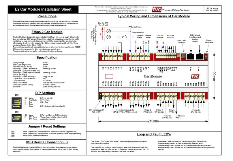
A basic Ethos Two system comprises of the main control module, which includes the CPU board + TFT MMI Display
interface, Motherboard I/O and an associated Car module to interface to car calls and car I/O. Various options are
available for landing call entry, including 8 way or 16 way call cards, QuickFlex landing nodes or the HCD navigator
system (See TVC factory for details). The main control module is equipped with a clear and intuitive touch screen
user interface with short cuts for fast and easy menu navigation.
Systems requiring more floors and or features can take advantage of plug in expansion modules; such as the 24
way output module and 8 way input or output modules. As the Ethos Two system is a modular system multiple
modules can be plugged together to form one contiguous modular Ethos Two system.
The Ethos Two control system uses a distributed field-bus network for interfacing calls and I/O to the main Ethos
Two lift controller. The field-bus uses a proprietary CAN bus protocol developed by TVC. The system is used in
place of normal discrete wiring for calls and car related input and outputs. Instead of each push and call lamp being
directly connected to the panel, in the motor room, they can be connected to local modules that are distributed about
the car and lift shaft. This will depend on particular installation requirements.
The systems voltages are derived from a transformer/power supply module mounted on the motor panel and are fed
via a wiring looms to the control modules. High reliability, field proven industrial standard components are used
throughout the system and are readily available from many sources.
The system has signal protection, where all external incoming signals are optically isolated and filtered. Motor panel
signals are mainly at 110Va.c and 24Vd.c. Call signals e.g. landing and car push feeds / acceptance lights are
24Vd.c.

Page 7 of 102
TVL 351
ISSUE 15
2.4. System Key Features.
Ethos Two is a modular lift control system, various expansion cards can be fitted to the system to allow for more
calls and features. The system can be configured to function as an 8 car dispatcher-less group or a Hall Call
Destination system in conjunction with the TVC Navigator system. The system uses several CAN bus connections to
facilitate this. Consult the contract drawings and expansion module section for further information.
The system can be configured with the following limits:
Number of Floors: 64 front and rear openings, short floors (min 20mm), long floors.
Group Operation: 8 cars Dispatcher-less or 8 cars Hall Call Destination.
Machine: Traction - AC / DCSCR, Hydraulic, Hydraulic – Electronic.
Speed: 0.3 – 8.0 m/s.
Features: Re-levelling / Advanced door opening / Advanced brake lift.
See Service / Feature descriptions for full list.
The Ethos Two builds on the original Ethos controller from TVC with these key new features:
Ethos Two is based around a simple, intuitive touch screen that provides a clear indication of the lift’s current status.
The screen gives the user all the information they need, at their fingertips. Extensive help for all features and faults
is displayed on the screen in plain English.
The new Car Module contains the “RideSensor” option. This records car ride performance via a 3-axis
accelerometer, checks the ride performance in real-time and can spot any issues before the passenger does. G-
force-limit records ‘Over G’ events such as crash stopping or safety gear operation which is useful for analyzing
passenger claims of abrupt journeys.
The new event logger stores every event against a time-line including direction, position, load, inputs & outputs.
Colour coded fault finding filtering critical and non-critical events and searching options quickly help get to the core
of a problem. All events are stored on a large memory Micro SD Card this can store years of archived events for
future reference.
Service Alerts record the number of operations of key components. As well as recording door and journey counts, it
records door operations per floor for an indication of landing door gear wear.
Parameter storage on the SD Card allows easy transfer of settings, this makes upgrades and repairs faster and
simpler, no special software is needed to upgrade the firmware of the device, so software upgrades can be
performed without waiting for an engineer with dedicated tools.
The Ethos Two has many handy automated features including: Automated shaft self-learning and automatic
stopping point adjustment for quicker installations.
Integrated speed pattern generation with “Direct-to-Floor” approach, so no need to adjust slowing distances and
speeds for different floor heights. The pattern also allows alternate speed profiles to be selected. Profiles include
ride settings for Comfort, Economy and Ultimate Performance.
A serial drive interface provides fault information from the drive, integrated into the logger.
Hoist Mode allows the elevator to be controlled during installation without all features connected. Jog motor feature
gives the engineer the option to run the motor from the screen to check starting and stopping performance.
Machine room-less installations are easier with the CAN serial modular system that allows for flexible installations
with either shaft or panel mounted modules. The main control module also has a remote MMI feature that can be
mounted in the smallest of rescue panels.

Page 8 of 102
TVL 351
ISSUE 15
2.5. Main Controller Specification
System Supply: 400V a.c. + 10% - 15% 50 Hz. Note: Other voltages available - consult factory.
Main Processor Specification
Supply: 24V d.c. / 0.5A (12W)
Low power shut down voltage: 20V d.c.
Max Voltage on 110V inputs: 120V
Max Voltage on 24V inputs: 30V
Max Voltage on outputs: 120V
Lift + MMI CPU Board: 32bit ARM CPUs with 4Mb Byte Flash, 24Mb RAM.
Features:
3 to 5 CAN Ports
2 to 3 RS232 Ports
2 to 3 RS485 Ports
Ethernet 10/100M
USB
5-24V Incremental Encoder Interface
Digital and Analogue Speed Pattern
7" TFT touch screen (800x480)
Mono audio.
2.6. Environment
Storage Temperature: -10 ºC to +60 ºC
Operating Temperature: 0 ºC to +40 ºC Note: The ambient temperature surrounding the
controller cabinet must be between 0 ºC and 40 ºC.
Humidity Operating Range: 0 - 90% relative humidity (non-condensing)
IP Rating IP2X Protect against dust, moisture and water ingress.

Page 9 of 102
TVL 351
ISSUE 15
2.7. Standards
The controller meets the following standards / specifications:
BS EN 81-20:2014. Safety rules for the construction and installation of lifts. Lifts for the transport of persons and
goods. Passenger and goods passenger lifts.
BS EN 81-50:2014. Safety rules for the construction and installation of lifts. Examinations and tests. Design rules,
calculations, examinations and tests of lift components.
BS EN 12015:2014. Electromagnetic compatibility. Product family standard for lifts, escalators and moving walks.
Emission.
BS EN 12016:2013. Electromagnetic compatibility. Product family standard for lifts, escalators and moving walks.
Immunity.
BS EN 81-73:2016. Safety rules for the construction and installation of lifts. Particular applications for passenger
and goods passenger lifts. Behavior of lifts in the event of fire (if requested)
BS EN 81-72:2015. Safety rules for the construction and installation of lifts. Particular applications for passenger
and goods passenger lifts. Firefighters lifts (if requested)
BS EN 81-1:1998+A3:2009. Safety rules for the construction and installation of lifts. Electric lifts
BS EN 81-2:1998+A3:2009. Safety rules for the construction and installation of lifts. Hydraulic lifts
2.8. Certificates
Certificates for EMC compliance and Safety compliance can be supplied when requested - see factory.
2.9. Help - Fault Finding Procedures
Ethos Two provides a number of software tools designed to assist the engineer in fault finding, these tools are
simple to use, The key fault finding tools include:
The “Solutions” button, takes you to a list of current out of service events.
The “Event Logger”, with extensive help system and out of service “Time Line”.
The “Help” key on the main screen, gives an overview on MMI and hardware operation.
Context sensitive help is always available on the screen footer.
See overleaf for a description of the main CPU.

Page 10 of 102
TVL 351
ISSUE 15
2.10. Main Controller CPU Hardware
Configuration Switches and Layout
Main CPU
Switch Description Normal Position
SW7 Watchdog Disable Norm (Lower)
SW8 Main CPU Reset Switch. OFF (Not Pressed)
SW9 (C1) Bootloader Activation OFF
SW9 (C2) Shaft Encoder Factory Test OFF
SW13 (1) ETSD Card Disable OKS. ON (if ETSD Card not fitted) / OFF (if ETSD Card fitted)
SW13 (2) ETSD Card Disable Pattern. ON (if ETSD Card not fitted) / OFF (if ETSD Card fitted)
SW14 Encoder Supply Link in 24V position
CAN1 TERM
Termination for Group Bus ON (if end node on Group bus)
CAN2 TERM
Termination for Expansion Bus ON (if end node on the bus e.g. no EMU)
CAN3 TERM
Termination for ABS Enc. ON (normally used for Absolute Encoder)
TC2 COM2 RS485 Termination OFF
TC3 COM3 RS485 Termination OFF
ABS Encoder Bias Resistors OFF (used for single ended encoder signals)
ABT Encoder Termination OFF
MMI Board
Switch Description Normal Position
SW5 MMI CPU Reset Switch. OFF (Not Pressed)
SW4 (C1) Bootloader Activation OFF
SW4 (C2) Touch Screen Calibration OFF
ETSD Card
Switch Description Normal Position
SW3 Bootloader Link Upper Position (Edge of board)
SW1 ETSD CPU Reset Switch. OFF (Not Pressed)
SW2 (1) Not Used OFF
SW2 (2) Not Used OFF
SW2 (3) Not Used OFF
SW2 (4) Bootloader Activation OFF
SW4 (CAN 4)
Termination for ABS Enc. ON (normally used for Absolute Encoder)
SW5 (CAN 5) Termination for Landing Bus ON (if end node on landing bus)
J4 COM4 RS485 Termination OFF

Page 11 of 102
TVL 351
ISSUE 15
170mm
SD2
CN1
CONC
TFL
GND
SGS
GND
OS
GND
MC
BKR
BLC1
BLC2
SI1
SI2
CN2
MRT
FSR
FAM
EMR1
TFR
BFR
LFS
CFS
DZ
RDZ
SI3
0V1
ALM1
ALM2
SI7
SI6
SI5
SI4
0V3
SO3C
SO3B
SO3A
GND
RL0V
RL24V
PS
CN3
LAR
TTR
PTR
TUP
TDN
NERR
GND
CG
GND
GL
GND
OKS
SAF
PUR
PDR
AROA
AROB
GND
DZA
DZB
DZC
RDZA
RROA
RROB
LOSIC
LOSIB
LOSIA
BROB
BROA
DEOB
DEOA
SO1A
SO1B
SO2A
SO2B
COM3
COM2
E-NET
COM4
COM1 CAN1
CAN1
CAN2
CAN3
CAN4CAN5
SD2
USB
C2T
C3T
CAN3 T
CAN2 T
C1T
5A d.c.
Output
24V
Supply
ET
ES
0V
B#
B
A#
A
ET
Earth / Screen
Encoder Supply
0V Return
Channel B Invt.
Channel B
Channel A Invt.
Channel A
Earth / Screen
COM
N/C
N/O

Page 12 of 102
TVL 351
ISSUE 15
3. MMI – Quick Start
The Ethos Two is fitted with a 7” touch screen as standard; this offers the user a comprehensive and easy to use
menu system, and allows extensive built in help screens so problems can be diagnosed swiftly and accurately.
The figure overleaf gives an overview of the main MMI features; feel free to press the buttons on the touch screen to
explore each feature in more depth.
3.1. MMI Key
Fixed button that can be pressed for additional features / menus.
Programmable button, tap to access function, touch and hold to assign a different function.
Main navigation Buttons.
No touch function, Information or Inactive button.
Active Feature.
Additional help and hardware connection diagrams are available in the toolbox menu.
Some screens will require you to login – the password is set to [222222] for technician level access.
3.2. Screen Calibration
If the touch screen is behaving inaccurately, please carry out a screen calibration.
Press: Toolbox → Calibrate Screen.
Follow the on screen prompts to re-calibrate the screen.
If the touch screen isn’t working at all, turn on DIP 2 on SW4 on the MMI and reboot the MMI by pressing the reset
button directly under SW4. The processor will now reboot into screen calibration mode. Follow the on screen
prompts to re-calibrate the screen, turn DIP 2 off after use and reset.

Page 13 of 102
TVL 351
ISSUE 15

Page 14 of 102
TVL 351
ISSUE 15
4. Service and Feature Descriptions
4.1. Main Modes of Operation
Normal or Automatic
This is the default mode of operation signified by the LAR input to the controller (Lift Available Relay),
Whenever the LAR input is de-energised, for example, due to the stop switch being operated, or the lift being
switched to inspection control, all car and landing calls will be cancelled and the ‘LISI’ (Lift In Service) indicator will
be off. (This LISI indicator is only provided when requested).
Door Disable
When enabled through the MMI, Door Disable inhibits normal operation of the door operator.
Also in this mode the lift can be moved via the MMI buttons in the “Jog Up/Down” screen, when Jog Motor mode is
active.
Prepare to Test
When enabled through the MMI, Prepare to Test assists in the commissioning or maintenance by inhibiting landing
calls and responding only to car calls, Doors park closed in the absence of car calls.
Inspection Control and Pit Inspection Control
When in these modes the car top / pit test buttons enable lift movement. During this time no calls will be accepted
and all features such as Fire or Service control are disabled. The lift will only move if the car top inspection buttons
are pressed or the pit inspection buttons are pressed (if fitted).
Emergency Electrical Operation
When in this mode the panel test buttons enable lift movement. During this time no calls will be accepted and all
features such as Fire or Service control are disabled. The lift will only move if the panel test buttons are pressed.
This mode is overridden by Inspection Control.
Installation Hoist Mode
When the controller is in installation hoist mode, activated in the checklist menu, the motor can be run on inspection
or emergency electrical operation without the CAN2 car / expansion network plugged in. Turn off after installation.
4.2. Call Collective Modes
The Ethos Two has a selection of call collection options, see below. Some of these options require additional
external modules so need to be requested at panel build time.
Full Collective
Up / Down landing calls answered in sequence, in the current direction of travel.
Down Collective
Down landing calls answered in sequence in the down direction, starting from the highest call.
Non Selective
Single call at each landing is answered irrespective of direction.
Hall Call Destination
Destination calls entered via keypad or touch screen at each landing (see TVC Navigator).
APB Control
APB operation offers the simplest form of lift service whereby the car responds to a single call and inhibits insertion
of further calls whilst the lift is in use. This mode of operation is suitable only for simplex installations and is typically
limited to low-rise goods lifts particularly manual gates installations. A Lift In Use Indicator (LIUI) warns other users
of the temporary unavailability of the car.
APB Car Call Preference temporarily inhibits landing calls to allow car call entry by the lift occupant. The APB Car
Call Preference timer restarts on arrival at a landing or when the doors open or close. The timer period can be set in
the settings menu under “Calls”.
The APB Last Car Call feature allows the lift occupant to change the current car call destination by pressing an
alternative car push. With APB Last Car Call operation turned off the user is unable to change the car call
destination once a car call has been accepted i.e. the existing car call must be serviced before another car call can
be entered.

Page 15 of 102
TVL 351
ISSUE 15
4.3. Group Operation
Press: Settings → Search Settings → Group or Parking or Peaks
The Ethos Two can be configured as a simplex or dispatcher-less group with up to 8 cars. The system can also be
setup with a standalone dispatcher or HCD dispatcher (Navigator) system. Various settings for group operation are
listed below:
Dispatching Overview (Non – HCD)
Put simply the dispatching algorithm employed by Ethos Two aims to assign the oldest call to the best car. Special
processing routines bias the assignment of calls to close cars or cars with coincident car and landing calls. The net
result is a balance between the fair distribution of lift service to all floors and an intuitive assignment of cars.
Installers may adjust call preference and parking assignments for normal, up and down peak traffic. Additional
priority can be given to calls at the main floor during an up peak and a Lobby Car feature may be used to keep a
single car at the lobby for an extended period.
Dispatching functionality may be provided by a per car controller (dispatcher-less operation) or by a standalone
dispatcher. Conceptually Ethos Two uses a master / slave dispatching model where the dispatch master assigns
landing calls to all controllers in the group. The dispatch master / slave concept is applied to installations large or
small. A simplex controller is always a dispatch master, a duplex installation has one dispatch master and one
slave, a triplex installation has one dispatch master and two slaves and so on. Selection of the dispatch master
controller is completely automatic and does not disrupt service.
Each controller’s current dispatch master / slave status can be viewed by pressing the Toolbox → Group Network
button. In the Group Network Status screen is a graphic showing the status of each car in the group.
The five main dispatching options available to the user for configuration are:
Parking
Parking & Bus-Stop - Parks cars at predefined levels, separate parking assignments are available for normal, up
and down peak traffic. Bus-Stop service provides rudimentary lift service during landing riser failure.
Ethos Two provides discrete parking assignments for normal, up and down peak traffic conditions. For each of the
three traffic conditions an ON / OFF control, parking timer and parking assignment table has been provided.
Parking ON/OFF - Select ON to park idle cars or OFF to leave idle cars at their current floor level (default = ON).
Parking Timer - The Parking Timer determines the period of time in seconds between the car becoming idle and
assignment of the parking call (default = 10 seconds).
Parking Assignments - The Parking Assignments screen lists a table of parking levels in ascending order of priority
i.e. the first idle car will park at the level entered for Park Assign Index 1 the second idle car will park at the level
entered for Park Assign Index 2 and so on.
The floor entry for Park Assign 1 is also known as the Primary Parking Assignment, it receives a higher level of
coverage than the other parking assignments. A car parked at any of the other parking assignment levels can be
moved to the Primary Parking Assignment level if it becomes unoccupied. A car parked at the Primary Parking
Assignment level will not be re-homed to any other parking level.
The parking assignment table is scanned for non-zero entries from Park Assign-1 through to Park Assign-8. A value
of zero is ignored if there are fewer non-zero entries than the number of cars in service the number of cars allowed
to park is reduced to the number of non-zero Park Assign-levels.
By way of example the following configuration for a 5 car group assigns the first 3 idle cars to levels 1-3-5, the 4th
and 5th idle cars will not receive a parking assignment whilst the parking levels 1-3-5 are occupied:
Park Assign-1 1 (Primary Parking Assignment)
Park Assign-2 3
Park Assign-3 5
Park Assign-4 0
Park Assign-5 0
The Primary Parking Assignment (Park Assign-1) also specifies the Lobby Floor (see Lobby Floor below). The
parking assignment levels are unique to each site and should be adjusted as necessary by the installer.
Peaks
The Ethos Two has special call processing routines for up and down peak traffic. By selectively “aging” landing calls
preference can be given to a particular direction of landing call (also known as boosting).
During an up peak idle cars can be made to park at specified up peak parking levels (refer to earlier section on
parking) plus landing calls at the lobby and up landing calls at all floors can be boosted.

Page 16 of 102
TVL 351
ISSUE 15
During a down peak idle cars can be made to park at specified down peak parking levels (refer to earlier section on
parking) and down landing calls at all floors can be boosted.
By default, peaks are disabled and must be enabled by the installer once site traffic conditions have been assessed.
A full description of all parameters relating to peak processing follows.
Peak Invocation - Peak processing is invoked by one of three triggers:
1. Input activation, peak processing begins on activation of the relevant input (refer to job specific wiring
diagrams) and persists until the input is deactivated.
2. Timer activation, peak processing starts and ends at user definable times.
3. Automatic activation, peaks begin when the appropriate start conditions have been met and persist for
the duration of the peak traffic condition or at least as long as the user definable peak duration time.
Peak Prioritisation - When up and down peaks coincide activation adheres to the following sequence (highest to
lowest):
Input activated down peak
Input activated up peak
Timer controlled down peak
Timer controlled up peak
Automatic down peak
Automatic up peak
Up Peak
Defines the up peak traffic start conditions, choose between input, time clock or automatic initiation. Provides a
boost for calls at the main floor during up peak traffic.
Inputs: "UPK ", "Up Peak Input"
Down Peak
Defines the down peak traffic start conditions; choose between input, time clock or automatic initiation.
Inputs: "DPK ", "Down Peak Input"
Group → Lobby Service
Delays cars leaving the lobby floor to encourage higher occupancy.
Group → Floor Preference Boost
Provides user settable boosting of calls at individual floors.
On delivery to site, controllers are pre-set with default settings. The default settings provide a good level of service
for a wide variety of conditions however; Installers may choose to configure the dispatching features for optimum
performance on each site.
Step By Step Guide To Dispatcher Configuration
The following guide is an optional series of steps that may be followed by the installer to tune group performance.
Peak configuration should be performed with all cars in service. Knowledge of traffic patterns and building
population is a prerequisite to dispatcher tuning. An Ethos Two group that is not tuned on site will still provide good
service. Incorrect configuration may produce a serious reduction in group performance.
Step 1. Check normal homing levels have been defined appropriately and homing is enabled. A homing time of 10
seconds is typical.
Step 2. Define parking levels for up and down peak traffic. If peak parking levels are not required, ensure the peak
parking assignments are set to the same levels defined in the normal parking assignment table.
Step 3. Depending upon which peak activation trigger is used (input, timer or automatic) set peak timers or
automatic detection parameters as required.
The active peak mode is displayed on the Ethos Two main status display. Events are stored in the event log to mark
the start and end of each peak. If automatic peak detection is required, use the following guidelines.
For automatic up peak activation start out by increasing Max Down Calls and reducing Min Car Calls and Min
Loaded Cars from their default values. By monitoring the number, duration and time of up peak events in the event
log optimal sensitivity of the system can be obtained. Similarly, for automatic down peak activation Max Up Calls
should be increased and Min Down Calls reduced from the default settings until the required sensitivity has been
reached.
Be conservative with Up and Down peak weighting. It is recommended that these parameters be left set at the
default value of zero. Even moderate values can lead to an increase in the number and duration of long wait times
for reverse traffic flow.
Step 4. For ad hoc boosting of specific floors, use Floor Preference. Set Floor Preference back to zero when
boosting is no longer required.
Step 5. Use Lobby Service to increase utilisation of cars at the lobby if necessary.
Note that whilst parked at the lobby level the lobby car will not be assigned landing calls from other levels.

Page 17 of 102
TVL 351
ISSUE 15
4.4. Door Settings
Press: Car → Settings or Settings → Search Settings → Door
The key door settings can be found behind the Car button and in the Search Settings menu. Ethos Two can be
configured for all major door operators, manual gates and swing landing operation. Any combination of front and
rear door openings can be requested. Each door parameter gives a description of its use and units.
Door Dwell
Dwell timers dictate the time the doors stay open when answering car, landing or combined calls.
Door Operation
Operation parameters such as whether advanced door opening or nudging is active can be found here. Delay timers
for reversal and contactor operation are also located here.
Door Protection
Door protection timers for opening and closing cycles can be adjusted as well as gate open warning timers for
manual gates and safety edge timeout timers.
4.5. Indicator Settings
Press: Indicators & Speech or Settings → Search Settings → Indicators & Speech
All indicator and speech unit settings can be found behind the Indicator and Speech button and in the Search
Settings menu. Ethos Two can be configured to serially control several 3rd party manufacturers’ encoder units, as
well as control encoders that are discretely wired. Binary / Gray code and discrete position indicators can be
controlled. The flexible I/O available can cover anything from hall lanterns to BMS signals. Options for indicator
testing are also under this menu. Each indicator parameter gives a description of its use and units.
Base Indicator Settings
This menu contains basic indicator setup parameters, such as whether the PI/BI outputs are used and any binary
offset. Serial indicator communications modes etc.
Lanterns and Gongs
Settings for hall Lanterns and Gongs are under this heading. The Gong test feature can be activated here also.
Lift In Service
The indicators can be setup to show Lift In Service – LISI or Lift Out Of Service – LOSI. Some features can be setup
to active the lift in service indicator or not e.g. Inspection control activates LOSI.
Serial Speech Msg. Enable
Numerous speech messages can be activated or silenced depending on configuration here. For example: whether
the indicators show if the alarm button has been pressed.
Speech Hush Times
This time window start/finish determines when the speech unit volume is turned down, normally during the night.
Speech/Gong Triggers
There are various options for triggering the floor arrival speech messages. For traction lifts using the integrated
speed pattern the message can be announced on the estimated time of arrival to floor. For other setups e.g.
hydraulic lifts the trigger can be delayed dependant on single / multi floors journeys. Gong delay and trigger pulse
duration can be adjusted here.

Page 18 of 102
TVL 351
ISSUE 15
4.6. Optional Service and Feature Descriptions
The Ethos Two has a multitude of standard methods of control built in, the feature list below gives a brief description
of the main services and features. Some of these features require additional external circuitry so need to be
requested at panel build time.
Access to the feature settings can be found behind the MMI “Settings” button.
Press: Settings → Search Settings → Services / Features
Accelerometer
The 3 axis accelerometer mounted on the Car Module board can be used to report abnormal stops or an “Over G”
event.
Anti-Nuisance Control
Monitors the lift use to determine if inappropriate call inputs are being set.
Auto Recovery
If the controller senses a fault and has tried 3 times to start a journey or door cycle it will go out of service, the auto
recovery feature extends the number of attempts to move.
Auto Run / Burn In Test
Auto Run can be used to test the lift for up to 24 hours before it’s entered into service, in this mode car calls will be
entered automatically, this feature can be used with or without door disable.
Bus Stop / Dispatch Failure
If the controller cannot accept landing calls due to a group bus fault or landing push feed fault it will go on to bus
stop mode to allow a limited service.
Cabinet Fan
Limits the cabinet fan to between certain hours if needed.
Outputs: "CFAN ", "Cabinet Fan"
Car light Control
Car light control used to turn off the lift car’s fan and light when the lift is not in use.
Outputs: "CLT ", "Car Light Output"
Eco Mode
Programmable by time of day, with staged count down timers, when active.
Any ‘Wake-up’ signal will cancel Eco-Mode and return the lift to normal service.
Wake-up signals include car or landing calls, special service, fire control, inspection operation and touch screen
activation. Stage 1 (Snooze) after an adjustable period of inactivity. The car light and fan will be switched off. Stage
2 (Sleep) after a second period of inactivity. Shutdown drive and unneeded control circuitry, turn off unnecessary
LEDs and backlights. Stage 3 (Hibernate) after a third period of inactivity. Shutdown indicators, speech, call button
dual-illumination and other peripherals.
During activated Eco-Mode periods, the controller will select the “Low Energy” ride profile, this is used if calls are
below an adjustable level or the lift is on a homing run or other non-critical journey. Low Energy mode is deactivated
if multiple calls above the call limit are accepted.
Outputs: "EC1 ", "Eco Mode Stage 1" + "EC2 ", "Eco Mode Stage 2"
Emergency Power
On ESUP input activation: -
Puts all cars in emergency power mode, so they stop at next floor and wait for next command. Lifts will display
Emergency Power in the Mode entry on the status screen.
If the car does not have the duty flag, it will additionally display No duty Car as a fault in the status button.
Dispatcher then selects Duty Car: -
If dispatcher sets “duty car” across the network then we follow the next three inputs or flags from dispatcher. The
dispatcher gives duty to a car; this would then return to either the fire floor or the emergency return floor if FSR, FAM
or EMR are active. If not the dispatcher will request a recovery to the emergency supply return floor. The recover
flag from dispatcher causes the car to return to emergency supply floor only if duty car. FAM or FSR would also
return to fire floor only if duty car. EMR would return car to emergency floor if duty car.
FSR (Firefighting) phase 2: -

Page 19 of 102
TVL 351
ISSUE 15
If a car is already on fire phase 2 when ESUP is activated then this is automatically the duty car and will stay that
way.
When all cars are returned to their relevant floors or have been found to have stalled 3 times the fire duty car will
become Duty Car if it has not stalled.
Inputs: "ESUP ", "Emergency Supply"
Emergency Recall
Emergency recall takes the lift out of normal service and parks the lift at its recall floor. Three emergency recall
inputs provide recall to specified recall floors.
Inputs: "EMR1 ", "Emergency Recall 1" + "EMR2 ", "Emergency Recall 2" + "EMR3 ", "Emergency Recall 3"
Engineers Access
When activated Engineers Access Control will take the lift to a point in the shaft at levelling speed and then stop to
allow the lift engineer to easily gain access to the car top.
Inputs: "EAC ", "Engineer's Access Ctrl Ip" + "EAS ", "Eng's Access Stop Input"
Fire Recall
The lift will operate as EN81-73 describes: - Once initiated the lift will travel to the fire floor as soon as possible. If
the doors are open they will nudge closed, if available. Note: the door open push and the safety edge will be
ignored. If the lift is travelling in the wrong direction, it will stop at the next available floor and without opening its
doors return to the fire floor. When at the fire floor the doors will open and remain open. (They may be set to dwell
closed in customer settings). No car or landing calls can be entered. Throughout this service the FRI (Fire Recall
Indicator) output will be active.
Inputs: "FAM ", "Fire Alarm Recall"
Fire Service (Firefighting)
The lift will operate as EN81-72 describes: - Operation of a single pole Fire Control Switch installed on the main
landing will immediately initiate Phase 1 Fire Control Return.
Phase 1 Fire Control, the lift will return to the fire floor as quickly as possible. The following sequence of operations
will occur: -
All calls will be cancelled. If the lift is travelling away from the fire floor, the car will slow and stop at the next
available landing, the doors will remain closed and following a short delay the lift will start to return to the fire floor.
If the lift is travelling towards the fire floor, the lift will continue to the fire floor without interruption.
If the lift is at a landing with its doors open, the doors will nudge close immediately if available and the lift will
proceed to the fire floor, the door open push will remain operative in this phase.
Throughout the Fire Service Control sequence the "Fire Control" FCI indicator will be illuminated, landing calls will
remain inoperative and the Safety Edge (or the heat sensitive door devices) will be disabled.
Once at the fire floor the firefighting lift will park with its doors open and Phase 2 Fire Service operation will begin.
Phase 2 Fire Service, the following operations will exist on the firefighting lift:
Once they are fully closed, the doors will only open via constant pressure on the door open push. If the push is
released before the doors have fully opened they will automatically close. Once the doors are fully open they will
remain open until constant pressure of a call push causes them to close. If the call push is released before doors
are fully closed, the doors will re-open, all calls be cancelled and the lift will park with its doors open until a car push
is re-operated. The safety edge will be disabled.
Once the lift is moving, only one call will be accepted at any point, a new call entered will cause the original call to
be cancelled, the lift will travel to the last call entered. If moving away from the floor the lift will stop and reverse
direction. Once at the selected floor the doors will remain closed until signalled to open by constant pressure
operation of the door open push.
The lift will only return to normal operation if the fire control switch is in its 'Off' position, the lift is at the fire floor and
the doors are fully open.
Switching the fire control switch 'Off' for a minimum of five seconds and then to 'On' again, at any time, will always
cause the lift to return to the fire floor. Unless fitted with an in car fire switch, this switch must be on for the lift to
move whilst in phase 2.
Inputs: "FSR ", "Fire Service" + "FCS ", "Fire Car Switch"
Hospital Service
On entering a Hospital call the dispatching function will determine which lift will go on to Hospital service, all other
lifts in the group will stay on normal service. Only lifts capable of performing the service will be available. If a lift has
a fault, is on a higher priority service or is overloaded, then it is unavailable. A Hospital call cannot be placed at a
blank floor.

Page 20 of 102
TVL 351
ISSUE 15
The lift on hospital service will cancel all its car calls and landing calls, and temporarily remove any floor security in
place. The lift will then travel to the floor the hospital call has been placed, if the doors are currently open then it will
close them directly using nudging (if available), DOP to be ignored.
On arriving at the recall floor, the lift will open its doors and wait for a constant pressure car call to be placed onto
the lift. The doors will close and the lift will service the call. If no call is placed the service will time out and the lift will
return to normal service. On arriving at the selected floor, the lift will return to normal service.
If at any stage the lift develops a fault condition then it will cancel Hospital service.
Lift Alert Monitor
Prevents the lift starting a new journey if the system detects unintended movement.
Inputs: "MLA ", "Lift Alert Monitor"
Lift Isolation
Lift isolation takes the lift out of normal service, parking it at the next available floor.
Inputs: "LISL ", "Lift Isolated"
Limited Floor Service
Limited floor service provides an extra security map that is activated via an input, the real time clock, or both.
Inputs: "LTD ", "Limited Service"
LISI Self-Test
Allows the lift to put calls on so that the lift status is checked. Only active if [Self-Test Enable] is set and time is
within [LISI Daytime Start] and [LISI Daytime Finish].
Once active waits until car has been idle for [Test Delay Timer] time. Then the processor will place a call and the lift
will run to floor. Homing does not operate while in self-test mode.
Lift will then return to original floor after [Test Delay Timer] time. This will continue for [Max Number of Tests].
Load Weighing / 95% Load
Lift is on 95% Bypass and will not accept any more landing calls. If the car is fitted with a load sensing switch and
this switch is closed when the doors are closing, then the by-pass feature operates so that the car cannot stop for
intermediate landing calls and will only stop at the first car call encountered. Acceleration or retardation cannot
cause inadvertent operation of the by-pass feature.
Inputs: "WS95 ", "95pc weight switch"
Load Weighing / 110% Overload
Where the input WS110 is active the MPU will record the event, cause the doors to re-open and refuse to close until
the load is reduced. The event will remain displayed while this situation continues to exist, also the OLI output (Car
Overload Indicator) will be turned on. (Not active on Car Top Inspection Control).
Inputs: "WS11 ", "110pc weight switch"
Lobby Return
When on Lobby Return, all landing calls are cancelled and the entry of further car and landing calls is inhibited, but
existing car calls remain active. When the existing car calls are answered, the lift will then return to the predefined
Lobby Return Level where it will park out of service.
Inputs: "LRET ", "Lobby Return"
Low Pressure Return (if input assigned)
Available on hydraulic lifts, if the low pressure input is activated the car will recall to the lowest floor and shutdown.
Inputs: "LPI ", "Low Pressure Input"
Milkman’s Service
Milkman’s service takes the lift out of normal service and places control to a driver of the car. The driver places
single car calls to drive the lift to its required destination. Upon arrival at the destination, the lift will park open until
either the Cancel Milkman’s Service Timer expires or entry of a further call. The Cancel Milkman’s Service Timer will
start as soon as the milkman’s input is active. Should the timer expire or the input is present for a second time, the
lift will return to normal service.
Inputs: "MILK ", "Milkman's Service"
Remote Recall
Remote recall takes the lift out of normal service and parks the lift at its recall floor. It is control by TVC’s
E-Director system. E-Director provides a method of monitoring and controlling a lift from a PC.
Other manuals for Ethos Two
1
Table of contents
Other TVC Controllers manuals
Popular Controllers manuals by other brands

TECO-Westinghouse
TECO-Westinghouse SA7 instruction manual

COMEXIO
COMEXIO ZC300 manual

GREISINGER
GREISINGER GIR 230 Pt manual

Victron energy
Victron energy BlueSolar PWM DUO 12V 24V 20A LCD USB manual

Siemens
Siemens RWB27 Timeswitch Installation and operating instructions

Norlake
Norlake CP6 Series instruction manual