TVR AJP8 User manual

Main
Engine
Assembly

~.Jpa
Modification
Block
Modifications
-Early
Engines
Only
Firstly the lower bellhousing
mounting
t
ad
d
h]
,
on
ach
side
of
the blo
need modifiying. (LeftPosition
shown)
(Right Position
shown)
Modification 1is to drill through the
tapped
hole at the front
of
the casting to
diameter S.5mm...
...
and
then
tap
through, MJ 0 x
1.5
x
2.5
mm
deep.

Modification
Modification
ModifiCJltion
~
....
pa
tito drill
out
the
pump
mounting
hol to 8.5mm...
...
and
th s
then
need
th
edges
deburring
on
both
the
front sid
...
and
then
on
the
rear
side.
Main
Assembly
Engine -
Main
Assembly
Number
the main bearing
cup
with
an
engraver at the edges.
Mnin
Assembly
Main
Assf'lnbly
Main
Assembly
Ml1iIJ
Assembly
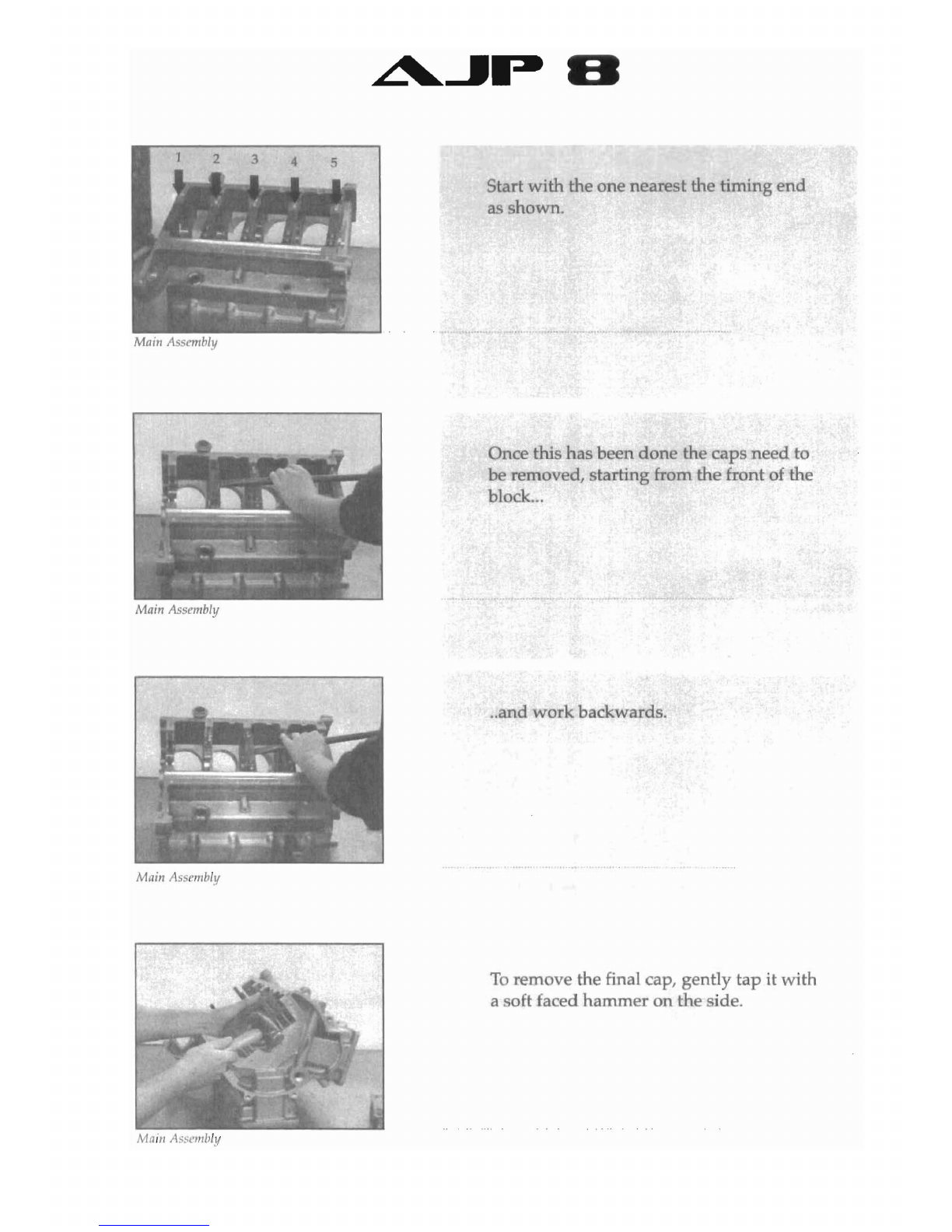
Start with the one neare tthe timing
end
as shown.
Once this
has
b n done the caps
need
to
be removed, starting from the front of the
block...
..
and
work
ba wards.
To
remove the final cap, gently tap
it
with
aoft faced hammer on the ideo

~...JP
El
MJIin
Assembly
Main
Assembly
Mod~ficali(ln
xt
the oil feed holes for th main
barings
ne
dto be deburred
...
...
and
any
sharp
edges
on
the
baring
bOT
sneed to
be
removed.
Modification
The edges
on
the thrustbearingbore
need
to
be chamfered
l.5mm
x
45
u
In
order for the
fly
wheel timing disc to
miss the oil gallery, the casting
needs
relieving ahown.
Modification
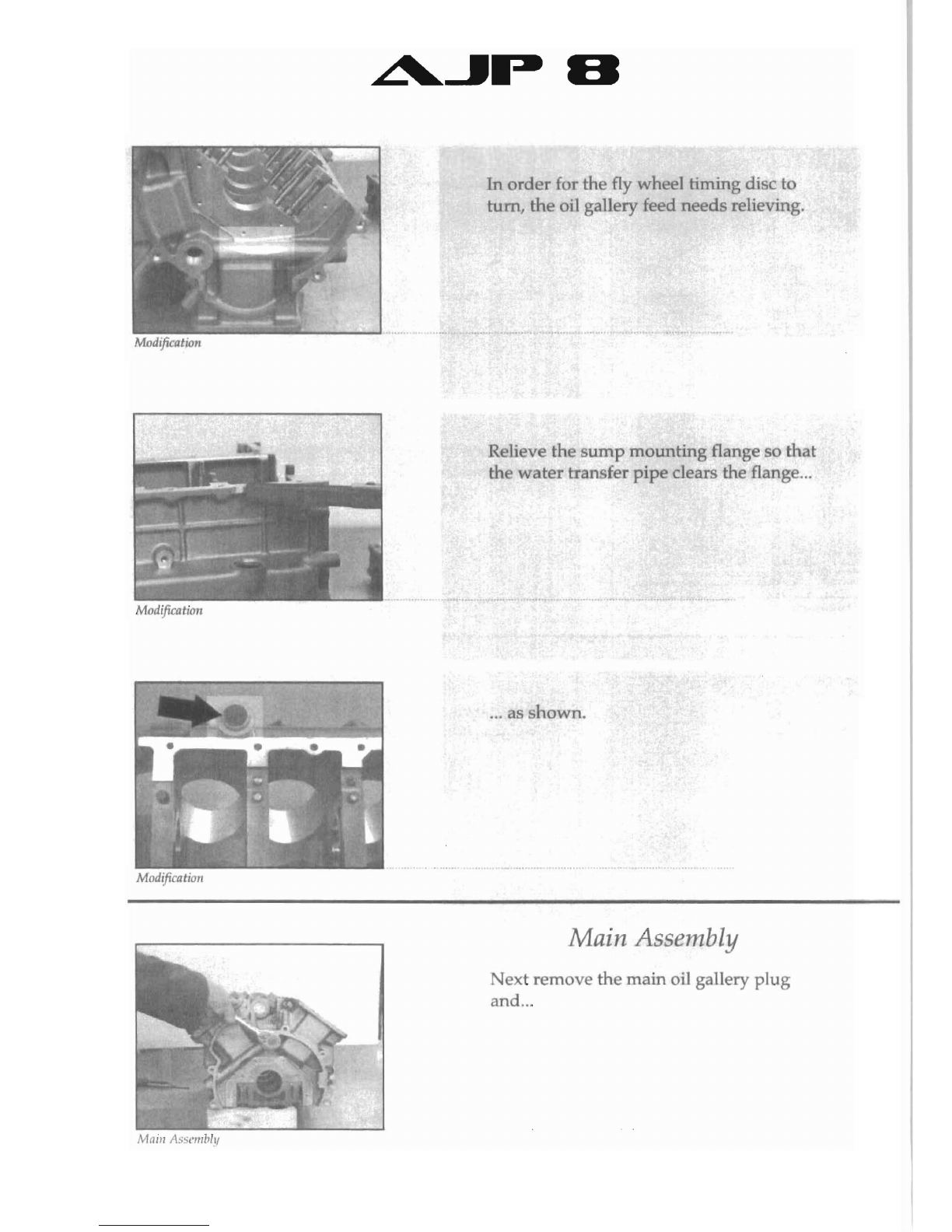
In
order
for the fly
wh
el timing disc 0
turn,
the
oil gallery f
ed
n
eds
relieving.
Modification
Maill
Assc1IIblt,
Rlieve th
sump
mounting
flange 0
that
th wte transf r
pipe
clears the flang
...
...
as hown.
Main Assembly
N
xt
remove
th
main
oil gallery
plug
and
...
L'....JP
El
Main
Assembly
Main
Assembly
Main
A~sembly
Main
ASSl'm/lll1
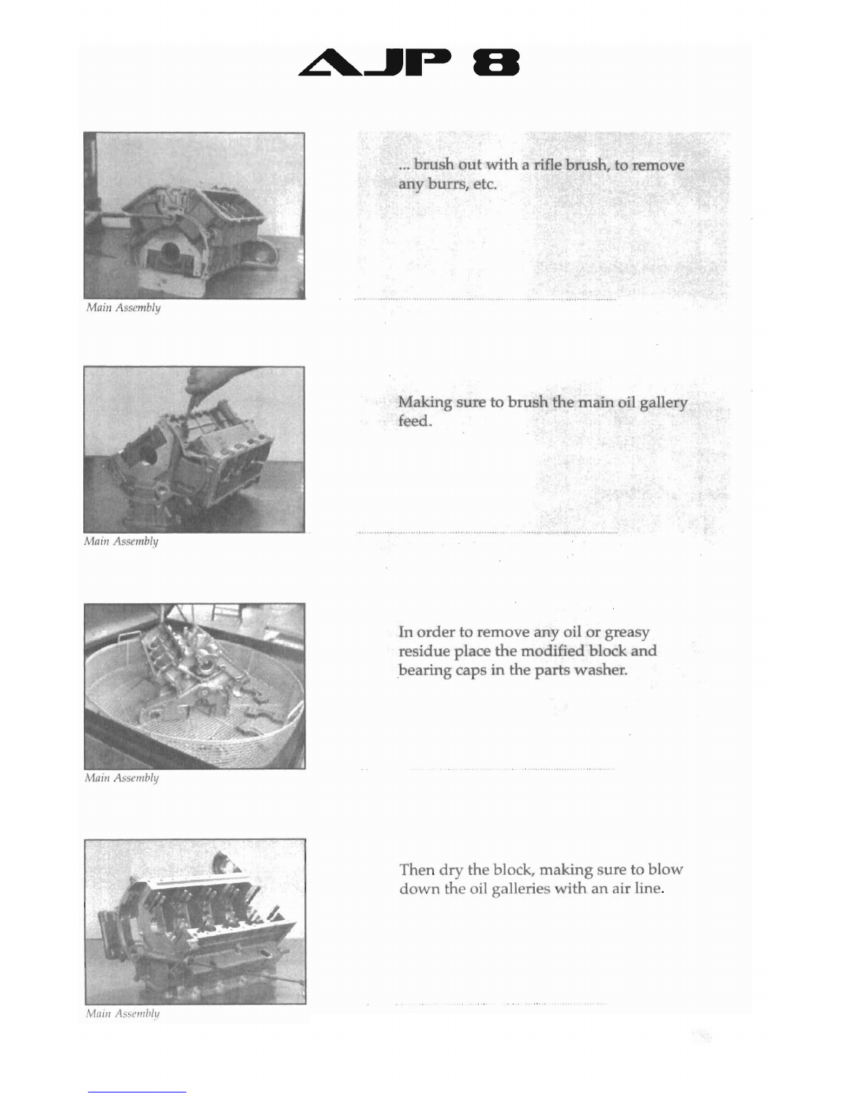
...
bru
h
out
with
arifle
bru
h, to remove
any
burrs, etc.
Making ure
to
brush
the
main
oil gallery
feed.
In
order
to remove any oil
or
greasy
residue place the modified block
and
bearing caps in the parts washer.
Then
dry
the block,
making
sure to blow
down
the oil galleries
with
an
air line.
El
Main Assembly
Main
Assembly
Main Assembly
Ma/ll
Asscl11/J1y
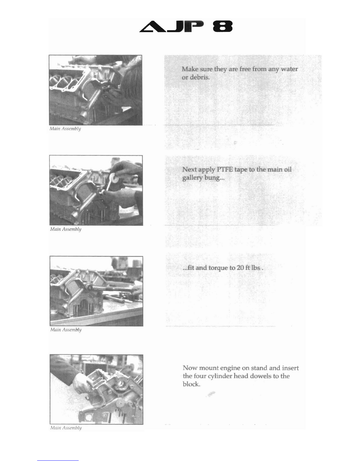
Make sure they r
fr
from any
wate
or
dbri .
ext
apply
PI'FE tape to the main oil
gallery
bung
...
...
fit
and
torque to 20
ft
lb .
Now
mount
engine
on
stand
and
insert
the four cylinder
head
dowels
to
the
block.
Main
Asembly
~...JP
El
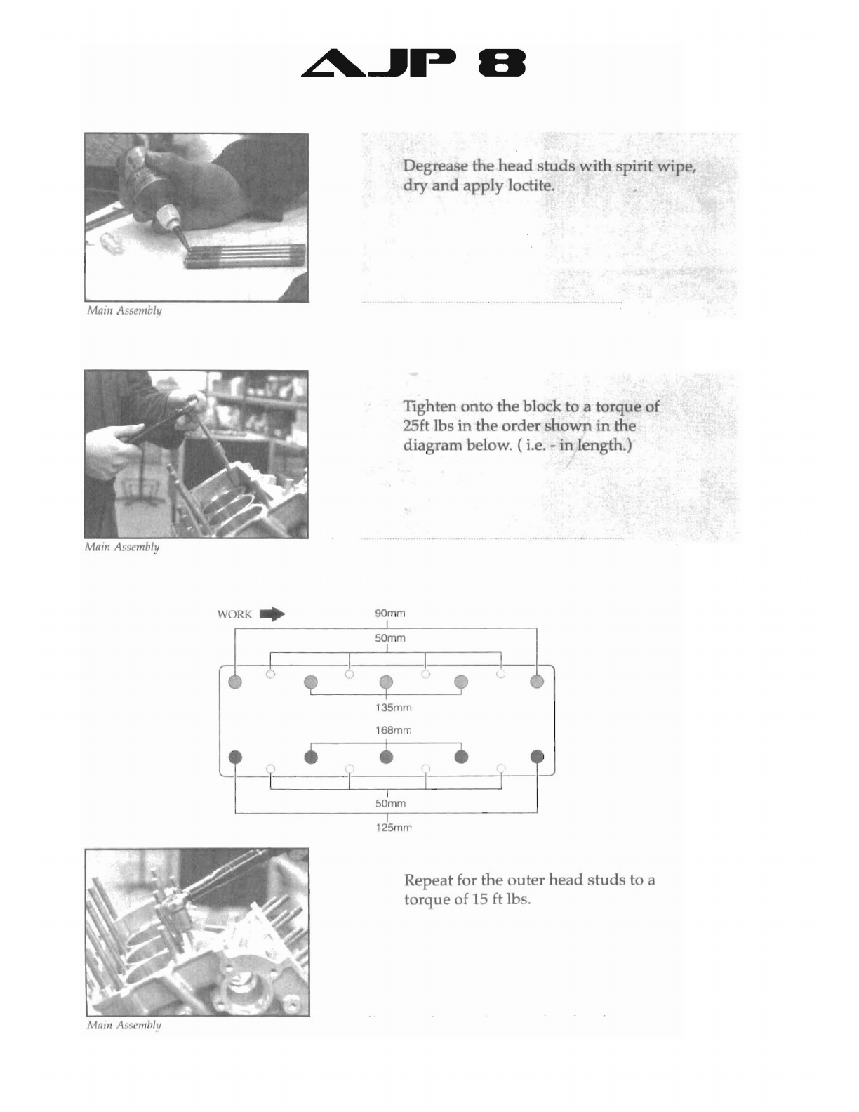
Dgre ethe
head
studs
with
spirit wipe,
dryand apply loctite.
TIghten onto
the
block to atorque of
25ft Ibs
in
the order shown
in
the
diagram below. (
Le.
-
in
length.)
Maifl
Assembly
WORK
..
90mm
f-h
5~mm
1
1
, I
135mm
168mm
1"•••J
I
I
-I
I
50mm
I
125mm
Repeat for the outer
head
studs to a
torque of
15
Et
lbs.

El
Marn Assembly
Main Assembly
Main
Asst'IIl/Jl.'l
Malll
Assm,bl.'l
Once fitted, the h
ad
tuds
should
be
level as
hown
in th picture.
Next
fj
tthe halftiro
bearing
as well as
th idl rpinion.
Using aoft driftinsert
the
jackshaft front
bearing.
Break the
sharp
edges on the bottom of
the liners
and
wash.
Table of contents


