10. Manual Recording
8. UPnP
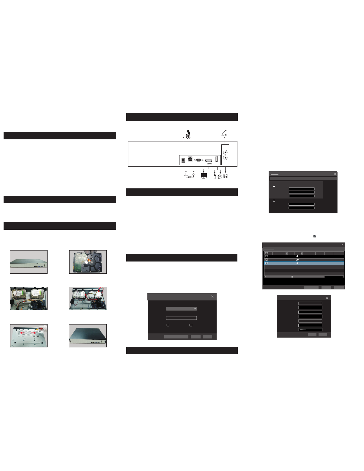
9. NAT
11. Playback
“Online” status means connecting the device successfully and you will
see the live image. You may select the added device and click button to
modify channel, IP address, ect.
Delet eEdit
Display Password
IP Camera Nam e
IP Address
Model
Edit IP Ca mera
XXX
192 .168 . 1 . 58
80
admin
XXX
Port
Username
Protocol
Password
IP Camera 3
OKTest Ca nc el
1
2
192.1 68.1. 20IP Ca me ra 1
192.1 68.1. 38IP Ca me ra 2
XXX
80 XXX
Onlin e
XXXOff li ne XX X80
Remai n Bandw id th: 8 5 / 12 0 Mb
No. C ame ra N ame IP Add re ss Port Pr otoco l M od el Pr ev iew
Statu s
Edit C amera Edit C amera Group
Search Ca me ra
3
192.1 68.1. 45IP Came ra 3
XXXOnlin e XXX80
►WAN
① Set the network of the NVR. Go to Start → Settings → Network → TCP/IPv4.
Input static IP address or enable PPPoE and then input the user name and password
received from your ISP.
② Go to Start → Settings → Camera. Click “Add Camera” or behind the
column of the search camera and select “Manually Add” to add the IP cameras.
Input IP address, server port, username and password of the IP camera. The IP
camera must be connected over WAN. And here the IP address of the IP camera
must be a WAN IP address.
►NAT Settings
① The NVR shall be powered on and connected to the network.
② Go to Start → Settings → Network → TCP/IPv4. You can obtain the IP
address, subnet mask and gateway automatically. You can also manually enter
them according to the actual network situation. Please make sure the network
segment is the same as that of the network which is used.
③ Set the preferred or alternative DNS Server. Click “Apply” to save the
parameters.
④ Go to Start → Settings → Network → NAT tab. Enable NAT and select
the NAT Server (The default NAT Server is nat.autonat.com). Click “Apply”
to save the parameters.
TCP/IPv4 P ort UPnP NAT
DDNS E-mail Network S tatus
nat.autonat.comNAT Se rver
Enab le
Apply
►NAT Access
After finishing the NAT settings, you can input www.autonat.com in the IE
address bar and then press enter to go to the following interface. If you are
the first time to access the NAT, you shall download and install the ActiveX
according to the popup tips. After installing ActiveX successfully, it will
pop the login box.
Before recording, please install and format a HDD. In the live interface
you can see the menu toolbar. Click button to start recording. Click
it again to stop recording. You can also click to check the status of
the recording.
►Instant playback
Click “Instant Playback” in the right-click menu of the camera’s preview
window to select or drag the playback progress bar to change the playback
time to play back the record.
►General playback
Click on the tool bar at the bottom of the live preview interface or click
Start → Playback to go to the playback interface as shown below. You can also
add the playback cameras manually. Click in the playback window to pop
up the “Add Camera” window. Check the cameras in the window and then click
“Add” to add playback camera. The record files of the added playback camera
will be played in the playback interface.
You can use the UPnP function to enable the fast connection of the device to
WAN via a router without port mapping.
① Go to Start → Settings → Network → UPnP, and enable UPnP and then
click “Apply” button to save.
② Enable the UPnP function in the router.
③Click “Refresh” button to refresh the UPnP status. If the UPnP status were
still “Invalid UPnP” after refreshing it for several times, the port would be
wrong. Please change the mapping type to “Manual” and then click to
modify the port until the UPnP status turns to “valid UPnP”.
HTTP Po rt
Serve r Po rt
80
6036
80183.1 7. 254.1 9 Vali d UP nP
Vali d UP nP
Inval id U PnP
6036183.1 7. 254.1 9
Port Typ e Ex te rnal Po rt Exter na l Addres s UPnP St atus Edit
Port
RTS P Port
554
554
TCP/IPv4 P ort UPnP
DDNS E-ma il NAT Network Stat us
AutoMap Type
UPnP
NAT
Enabl e
Refre sh A pply
450041000844 A1
Device Serial Number: Click on the menu bar at the bottom of the live
interface to check the serial number or go to Start → Settings → Network →
Network Status to check the serial number of the NVR).
Username: The username of the NVR. The default username is admin.
Password: The password of the NVR. The password is set by yourself when
you configure the wizard for the first time.
Enter Password
Enter Username
Enter device serial number
Login