Twinno 16540 User manual

twin no 天15
16540 p。lar。graphic
On-line Diss。lved Oxygen Meter
Operating Manual
上海淳业仪表科技杳限公司 l

Content
Preface................................................................................................................................................. 1
Features............................................................................................................................................... 2
Technical Specifications.......................................................................................................................3
Instrument installation........................................................................................................................ 4
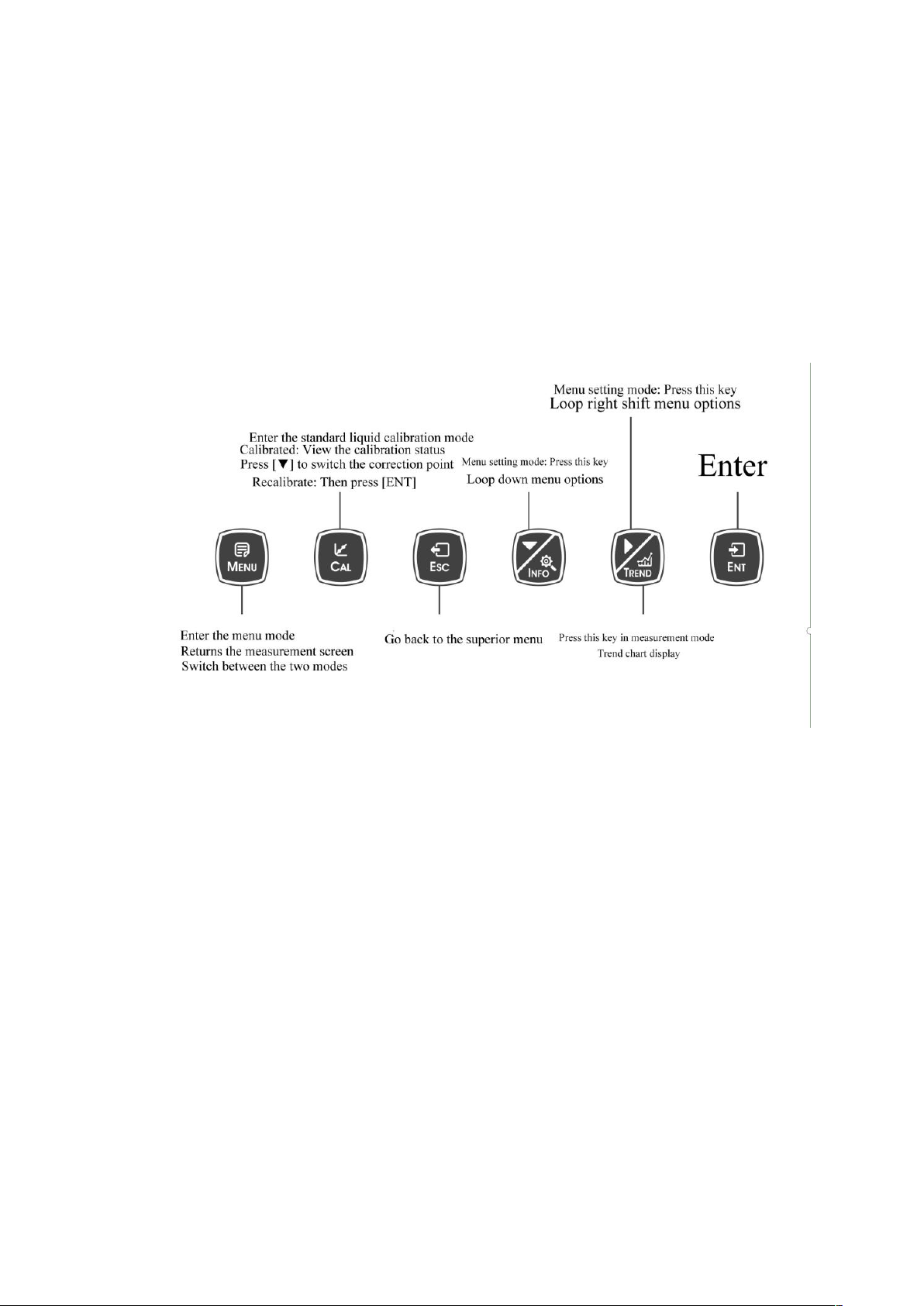
Keypad descriptions............................................................................................................................ 6
Display description.............................................................................................................................. 7
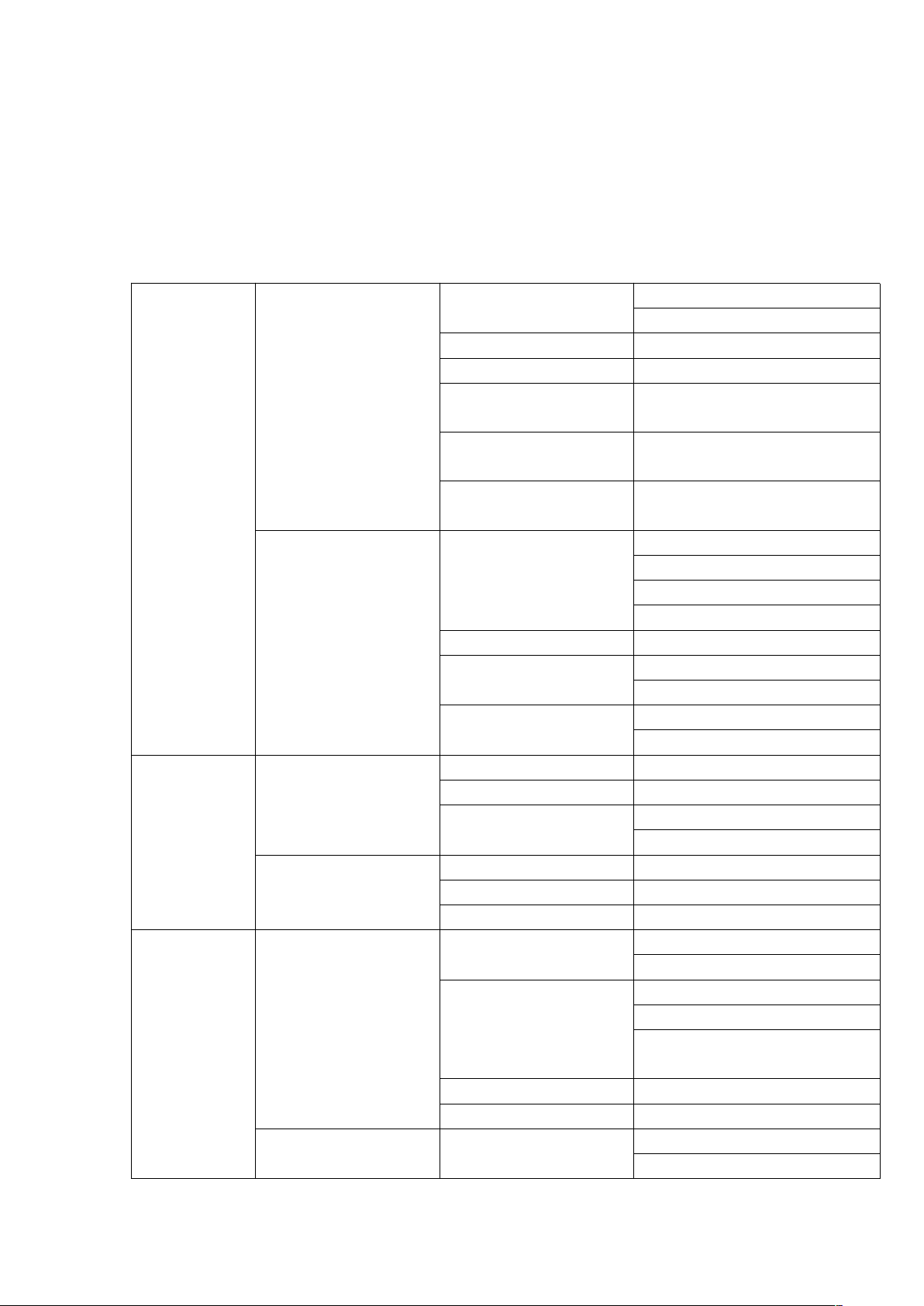
Menu Structure................................................................................................................................... 8
Calibration......................................................................................................................................... 11
Graphic Trend(Trend Chart)...............................................................................................................12
MODBUS RTU General Information..................................................................................................13
MODBUS RTU Transmission Mode................................................................................................... 14
MODBUS RTU CRC Check.................................................................................................................. 16
Implementation of MODBUS RTU in Instrument............................................................................. 16
Instrument MODBUS RTU function code..........................................................................................16
MODBUS function code 0x10: write multiple registers................................................................... 18
Data format in instrument................................................................................................................ 19
Read instruction mode......................................................................................................................22
Saturated Oxygen Meter in Water at Different Temperatures......................................................... 23
Daily maintenance.............................................................................................................................24
Frequently Asked Questions............................................................................................................. 25
Package Set........................................................................................................................................26
Warranty............................................................................................................................................27
Notes................................................................................................................................................. 28

1
Preface
Thank you for your support to us. Please read the instruction manual carefully before
use to help you use our products correctly.
When receiving the instrument, please carefully open the package, check whether
the instrument and accessories are damaged by transportation, whether the
accessories are complete, if abnormal, please contact our after-sales service
department or regional customer service center, and keep the packaging for return
processing.
Wiring or repair shall be done by a professional and operate only on instruments
with power-off. In the event of an instrument safety problem, power off the
instrument immediately to prevent any unintentional operation.
For example, it may be
Unsafe condition:
1) Significant damage to the instrument;
2) The instrument can not operate properly or provide specified measurements;
3) The instrument was stored in an environment with temperature exceeding 70℃
for a long time.
The instrument must be installed by a professional in accordance with relevant local
specifications, and the guidance instructions are included in the operating instruction
manual. Comply with the technical specification and input grade of the instrument.

2
Features
Industrial online dissolved oxygen meter is an online water quality monitor and
control instrument with microprocessor. The instrument is equipped with different
types of dissolved oxygen sensors. It is widely used in power plants, petrochemical
industry, metallurgical electronics, mining, paper industry, food and beverage
industry, environmental protection water treatment, aquaculture and other
industries. The dissolved oxygen value and temperature value of water solution are
continuously monitored and controlled.
●Color LCD display
●Intelligent menu operation
●Multiple automatic calibration function
●Differential signal measurement mode
●Three relay control switches
●High & low alarm and hysteresis control
●4-20mA & RS485,Multiple output modes
●Password protection function to prevent misoperation by non-staff.

3
Technical Specifications
Measurement range
0~40.00mg/L; 0~400.0%
Measurement unit
mg/L; %
Resolution
0.01mg/L; 0.1%
Basic error
±1%F.S
Temperature
-10~150℃
Temperature Resolution
0.1℃
Temperature Basic error
±0.3℃
Current Output
4~20mA,20~4mA,(load resistance<750Ω)
Communication output
RS485 MODBUS RTU
Relay control contacts
5A 240VAC,5A 28VDC or 120VAC
Power supply (optional)
85~265VAC,9~36VDC,power consumption≤3W
Working conditions
No strong magnetic field interference around except the
geomagnetic field.
Working temperature
-10~60℃
Relative humidity
≤90%
IP rate
IP65
Instrument Weight
1.5kg
Instrument Dimensions
235×185×120mm
Installation methods
Wall mounted

4
Instrument installation
Installation size

5
Connection between equipment and sensor: The power supply of relay, output signal,
alarm contact and connection between sensor and instrument are all inside the
instrument. Wiring is done according to Figure 3. The lead length of the cable fixed
by the electrode is generally 5-10 meters. Insert the line with corresponding label or
color on the sensor into the corresponding wiring terminal inside the instrument and
tighten it.
Wiring
Terminal
Function
Wiring Terminal
Function
SEN V+
Sensor Power+
NO 1
High set relay working position
SEN V-
Sensor Power-
COM 1
Alarm relay common
SEN A
Sensor Communication A
NC 1
High set relay resting position
SEN B
Sensor Communication B
NO 2
Low set relay working position
COM 2
Alarm relay common
N/C
NC 2
Low set relay resting position
Pow DC +(9-36V)
DC power +(9-36V)
Cure1+
Current output 1+
Pow DC-
DC power -
Com-
Current output common
Pow PE
Earth wire
Cure2+
Current output 2+
Pow ACL (85-265V)
Live wire
RS485 B
Communication Terminal
Pow AC N
Neutral wire
RS485 A
Communication Terminal
Pow PE
Earth wire

6
Keypad descriptions
Keypad operation tips:
Short Press: Short Press means to release the key immediately after pressing.
((Default to short presses if not indicated below)
Long Press: Long Press is to press the button for 3 seconds and then release it.

7
Display description
Before using should check all the pipe connection and electrical connection, after the
power supply, the instrument is shown as:

8
Menu Structure
The following is the menu structure of the instrument:
Configure
Sensor
Unit
Mg/L
%
Pressure compensation
101.3
Salinity compensation
0
Anaerobic oxygen
voltage compensation
0
Saturation oxygen
voltage compensation
20
Saturation oxygen
compensation
25
Temperature
Temperature Sensor
NTC2.252 kΩ
NTC10 kΩ
Pt100
Pt1000
Temperature Offset
0.0000
Temperature Input
Automatic
Manual
Temperature Unit
°C
°F
Calibration
Standard Solution
Calibration
Anaerobic calibration
Air Calibration
Calibrate correction
Offset Adjustment 一
Slope Adjustment 二
Field Calibration
Field Calibration
Offset Adjustment
Slope Adjustment
Alarm
Relay 1
Status
ON
OFF
High/Low Alarm
High Alarm
Low Alarm
Cleaning(cleaning time is set
in the cleaning output)
Limit Value
Hysteresis
Status
ON
OFF

9
Relay 2
High/Low Alarm
High Alarm
Low Alarm
Cleaning(cleaning time is set
in the cleaning output)
Limit Value
Hysteresis
Relay 3
Status
ON
OFF
High/Low Alarm
High Alarm
Low Alarm
Cleaning(cleaning time is set
in the cleaning output)
Limit Value
Hysteresis
Output
Current 1
Channel
Main
Temperature
Output Option
4-20mA
0-20mA
20-4mA
Upper Limit
Lower Limit
Current 2
Channel
Main
Temperature
Output Option
4-20mA
0-20mA
20-4mA
Upper Limit
Lower Limit
RS485
Baud Rate
4800BPS
9600BPS
19200BPS
Parity Check
None
Odd
Even
Stop Bit
1 Bit
2 Bit
Network Node
001+
Data Log
Graphic Trend
(Trend Chart)
1h
Display 480 points/screen
according to interval settings
12h
24h
Record Query
Input year/month/day
to query
Year/Month/Day,Time:Minute
s/Seconds Value Unit

10
Record Interval
7.5s
90s
180s
Memory information
101600point
Data Output
System
Language
Chinese
English
Date/Time
Year-Month-Day
Hour-Minute-Second
Display
Display Speed
Low
Standard
Medium
High
Backlight
Saving
Bright
Soft Version
Soft Version
19-1.0
Password Settings
0000
Serial Number
Factory Default
1.No
2.Yes
Terminal Current
Tuning
Current 1 4mA
(The positive and negative
ends of the ammeter are
connected to the current 1 or
current 2 output terminals of
the instrument respectively,
press 【▼】key to adjust the
current to 4 mA or
20mA ,press 【ENT 】key to
confirm.)
Current 1 20mA
Current 2 4mA
Current 2 20mA
Relay Test
Relay 1
(Select three groups of relays
and hear the sound of two
switches, the relay is normal.)
Relay 2
Relay 3

11
Calibration
Press [MENU] to enter the setting mode and select the calibration:
Calibration
Standard Solution Calibration
Anaerobic calibration
Air calibration
Field Calibration
Field Calibration
Offset Adjustment
Slope Adjustment
Calibration of Standard Solution
Select the way of Calibration, press the【ENT】key to enter the Standard Solution
Calibration. Or press the 【CAL 】button to enter the calibration mode of the
Standard Solution Calibration when in the measure screen.
If the monitor prompts you to enter the calibration security password, press the【▼】
key or 【►】key to set the calibration security password, and then press the 【ENT】
key to confirm the calibration security password.
Zero calibration Air calibration
Anaerobic calibration: after entering the calibration mode, the instrument display is
shown in the figure as above. Put the electrode with film cap into the Anaerobic
water (the matching electrolyte shall be injected into the film cap), and the
corresponding “Signal” value will be displayed on the left side of the screen. Press
【ENT】when “Signal” value is stable. During the calibration process, Done means
succeed, Calibrating means continue, Err means failure. Press【ESC】to go back when
it is finished.
Air calibration: after entering the calibration mode, the instrument display is shown
in the figure as above. Put the electrode with film cap in the air(the matching
electrolyte shall be injected into the film cap), and the corresponding “Signal” value
will be displayed on the left side of the screen. Press【ENT】when “Signal” value is
stable. During the calibration process, Done means succeed, Calibrating means
continue, Err means failure. Press【ESC】to go back when it is finished.

12
Field calibration
Select field calibration mode: [field calibration], [Offset adjustment], [linear
adjustment].
When the data from laboratory or portable instrument are input into this item, the
instrument will automatically correct the data. Input data by 【▼】【▶/TREND】,
press 【ENT】to calibrate, Done means succeed, Press【ESC】to exit.
Offset adjustment
Compare the data detected by laboratory or portable instrument with the data
measured by instrument. If there is any error, the error data can be modified by this
function.
linear adjustment
The linear value after field calibration will be saved in this item, and the factory data
is 1.00.
Graphic Trend(Trend Chart)
Press【Menu】key to enter the setting mode,set the recording interval, and the
instrument will save the data according to the selected recording interval time.
Data Log
Graphic Trend
(Trend Chart)
Record intervals/points
400 points/screen. Displays
the most recent data trend
graph according to record
interval Settings.
1h/point
400 points/screen. Displays
the last 16 days data trend
graph.
12h/point
400 points/screen. Displays
the last 200 days data trend
graph.
24h/point
400 points/screen. Displays
the last 400 days data trend
graph.
Record Query
Input year/month/day to
query
Year/Month/Day,Time:Minut
es/Seconds Value Unit
Record Interval
7.5s
Store data every 7.5 seconds
90s
Store data every 90 seconds
180s
Store data every 180 seconds

13
Press the 【Menu】button returns to the measurement screen. Press the
【▶/TREND】button in the measurement mode to view the trend chart of the saved
data directly. There are 400 sets of data record per screen.
In the current mode, press the【ENT】key to move the data display line to the left and
right (red). Long pressing of the 【ENT】key can accelerates displacement. (When the
bottom icon is green, [ENT] key is displacement direction,press
【▶/TREND】key to switch the direction of displacement ), and press to
switch the display range (enlarge/shrink).
MODBUS RTU General Information
Overview
The hardware version number of this document is V2.0; the software version
number is V5.9 and above. This document describes the MODBUS RTU interface in
details and the target object is a software programmer.
MODBUS command structure
Data format description in this document;
Binary display, suffix B, for example: 10001B
- decimal display, without any prefix or suffix, for example: 256
Hexadecimal display, prefix 0x, for example: 0x2A
ASCII character or ASCII string display, for example: "YL0114010022"

14
Command Structure
The MODBUS application protocol defines the Simple Protocol Data Unit (PDU),
which is independent of the underlying communication layer.
Figure 1: MODBUS Protocol Data Unit
MODBUS protocol mapping on a specific bus or network introduces additional
fields of protocol data units. The client that initiates the MODBUS exchange creates
the MODBUS PDU, and then adds the domain to establish the correct
communication PDU.
Figure 2: MODBUS architecture for serial communication
On the MODBUS serial line, the address domain contains only the slave instrument
address. Tips:
The device address range is 1...247
Set the device address of the slave in the address field of the request frame sent by
the host.
When the slave instrument responds, it places its instrument address in the address
area of the response frame so that the master station knows which slave is
responding.
Function codes indicate the type of operation performed by the server.
CRC domain is the result of the “ redundancy check” calculation, which is executed
according to the information content.
MODBUS RTU Transmission Mode
When the instrument uses RTU (Remote Terminal Unit) mode for MODBUS serial
communication, each 8-bit byte of information contains two 4-bit hexadecimal
characters. The main advantages of this mode are greater character density and
better data throughput than the ASCII mode with the same baud rate. Each message
must be transmitted as a continuous string.
The format of each byte in RTU mode (11 bits):
Coding system: 8-bit binary

15
Each 8-bit byte in a message contains two 4-bit hexadecimal characters (0-9, A-F)
Bits in each byte: 1 starting bit
8 data bits, the first minimum valid bits without parity check bits
2 stop bits
Baud rate: 9600 BPS
How characters are transmitted serially:
Each character or byte is sent in this order (from left to right) the least significant bit
(LSB)... Maximum Significant Bit (MSB)
Start bit
1
2
3
4
5
6
7
8
Stop bit
Stop bit
Figure 3: RTU pattern bit sequence
Check Domain Structure: Cyclic Redundancy Check (CRC16)
Structure description:
Instrument Address Data
CRC
1 byte 1 byte 0…252 byte
2 byte
CRC Low byte
CRC High byte
Figure 4: RTU information structure
The maximum frame size of MODBUS is 256 bytes
MODBUS RTU Information Frame
In RTU mode, message frames are distinguished by idle intervals of at least 3.5
character times, which are called t3.5 in subsequent sections.
Figure 5: RTU message frame
The entire message frame must be sent in a continuous character stream.
When the pause time interval between two characters exceeds 1.5 characters, the
information frame is considered incomplete and the receiver does not receive the
information frame.
Figure 6: Frame data transmission

16
MODBUS RTU CRC Check
The RTU mode contains an error-detection domain based on a cyclic redundancy
check (CRC)
algorithm that performs on all message contents. The CRC domain checks the
contents of the entire message and performs this check regardless of whether the
message has a random parity check. The CRC domain contains a 16-bit value
consisting of two 8-bit bytes. CRC16 check is adopted..Low bytes precede, high bytes
precede.
Implementation of MODBUS RTU in Instrument
According to the official MODBUS definition, the command starts with a 3.5
character interval
triggering command, and the end of the command is also represented by a 3.5
character interval.
The device address and MODBUS function code have 8 bits. The data string contains
n*8 bits, and the data string contains the starting address of the register and the
number of read/write registers. CRC check is 16 bits.
Value
Start
Device
address
Function
code
Data
Summary
Check
End
No signal
bytes
during 3.5
characters
1-247
1
Function
codes
conforming
to
MODBUS
specification
Data
conforming
to MODBUS
specification
CRCL
CRCL
No signal
bytes
during
3.5
characters
Byte
3.5
1
N
1
1
3.5
Figure 7: MODBUS definition of data transmission
Instrument MODBUS RTU function code
The instrument only uses two MODBUS function codes:
0x03: Read-and-hold register
0x10: Write multiple registers
MODBUS Function Code 0x03: Read-and-hold Register
This function code is used to read the continuous block content of the holding
register of the remote device. Request the PDU to specify the start register address
and the number of registers. Address registers from zero. Therefore, the addressing
register 1-16 is 0-15. The register data in the response information is packaged in

17
two bytes per register. For each register, the first byte contains high bits and the
second byte contains low bits.
Request
Figure 8: Read-and-hold register request frame
Response
Function code
1 byte
0x03
Start Address
2 bytes
0x0000….0xfffff
Read register number
2bytes
1...125
N = Register number
Figure 9: Read-and-hold register response frame
The following illustrates the request frame and response frame with the read and
hold register 108-110 as an example. (The contents of register 108 are read-only,
with two byte values of 0X022B, and the contents of register 109-110 are 0X0000
and 0X0064)
Request Frame
Response Frame
Number Systems
(Hexadecimal)
Function code
(Hexadecimal)
Function code
0x03
Byte count
0x03
Start address (high byte)
0x00
Register Value (High
Bytes) (108)
0x06
Start address (low byte)
0x6B
Register Value (Low
Bytes)(108)
0x02
Number of Read Registers
(High Bytes)
0x00
Register Value (High
Bytes) (109)
0x2B
Number of Read Registers
(Low Bytes)
0x00
Register Value (Low
Bytes) (109)
0x00
.
Register Value (High
Bytes)(110)
0x00
Register Value (Low
Bytes) (110)
0x00
Function code
1 byte
0x03
Start Address
2 bytes
0x0000….0xfffff
Read register number
2bytes
1...125

18
Function code
0x64
Figure 10: Examples of read and hold register request and response frames
MODBUS function code 0x10: write multiple registers
This function code is used to write continuous registers to remote devices (1... 123
registers) block that specifies the value of the registers written in the request data
frame. Data is packaged in two bytes per register. Response frame return function
code, start address and number of registers written.
Request
Function code
1 byte
0x10
Start Address
2 bytes
0x0000....0xffff
Number of input registers
2 bytes
0x0001....0x0078
number of bytes
1 byte
N×2
Register values
N×2 bytes
Value
N = Register number
Figure11:Write multiple register request frames
Response
Function code
1 byte
0x10
Start Address
2 byte
0x0000….0xffff
Register number
2 byte
1…123(0x7B)
N = Register number
Figure 12: write multiple register response frames
The request frame and response frame are illustrated below in two registers that
write the values
0x000A and 0x0102 to the start address of 2.
Request Frame
(Hexadecimal)
Response Frame
(Hexadecimal)
Number Systems
0x10
Number Systems
0x10
Function code
0x00
Function code
0x00
Start address (high byte)
0x01
Start address (high byte)
0x01
Start address (low byte)
0x00
Start address (low byte)
0x00
Input register number
(high bytes)
0x02
Input register number
(high bytes)
0x02
Table of contents
Other Twinno Measuring Instrument manuals

Twinno
Twinno T4050 User manual

Twinno
Twinno T6075 User manual

Twinno
Twinno T4058 User manual

Twinno
Twinno T6555 User manual

Twinno
Twinno T4046 User manual

Twinno
Twinno T6500 User manual

Twinno
Twinno T4055 User manual

Twinno
Twinno RM785 User manual

Twinno
Twinno T6055 User manual

Twinno
Twinno T4030 User manual