Twinno T6000 User manual

Shanghai Chunye Instrument Technology Co.,Ltd
Tel: 021-61621082
Fax: 021-61621099
Web: www.twinno.net
Add: Building 6, No.166 Mindong Road, Pudong New District, Shanghai, China
Post code:201209
T6000 pH/ORP Online Analyzer
Operating Manual
Shanghai Chunye Instrument Technology Co.,Ltd

23
Distinguished users, please pay attention to the following points when using the instrument, in
order to ensure the life and accuracy of the instrument.
ӹCareful handling to avoid collision and falling instruments in use.
ӹAvoid contact with water or other liquids during use.
ӹDon't put the instrument in the sunshine for a long time. After use, it should be stored in a cool,
dry and ventilated place.
ӹIf you don't use the instrument for a long time, you should unplug the power supply to avoid
accidents.
ӹThis instrument is not suitable for use in harsh environment, high temperature, low temperature
or strong magnetic field interference,which may lead to instrument damage.
ӹIf there is any problem with the instrument, please contact the dealer or the company. Do not
disassemble the instrument by yourself. If disassembled, the company will no longer be
responsible for the warranty.
Cautions Table of Contents
Preface
Features
Technical Specifications
Installation
Installation size
Instrument installation
Instrument connection
Keypad descriptions
Display descriptions
Menu structure
Calibration
Graphic Trend
MODBUS RTU
pH Buffer VS Temperature
Daily Maintenance
Package Set
Warranty
Cautions
1
1
2
3
3
4
5
6
7
8
10
12
13
20
21
22
22
23

1
Features
The instrument is equipped with different types of pH or ORP sensors. Widely used in power
plants, petrochemical industry, metallurgical electronics, mining, paper industry,
biological fermentation engineering, medicine, food and beverage, environmental
protection water treatment, aquaculture, modern agricultural planting and other
industries. The pH (acidity and alkalinity) value, ORP (redox potential) value and
temperature value of water solution were continuously monitored and controlled.
ӪLarge color LCD display
ӪIntelligent menu operation
ӪData Recording /Curve display/Data upload function
ӪMultiple automatic calibration
ӪDouble high resistance measurement mode, stable and reliable
ӪManual and automatic temperature compensation
ӪThree relay control switches
ӪHigh & low alarm and hysteresis control
Ӫ4-20mA&RS485 Multiple output modes
ӪMulti parameter display simultaneously shows – pH, Temp, mV,etc.
ӪPassword protection to prevent misoperation by non-staff.
Preface
Thank you for your support. Please read this manual carefully before use.The correct use
will maximize the performance and advantages of the product, and bring you a good
experience.
When receiving the instrument, please open the package carefully, check whether the
instrument and accessories are damaged by transportation and whether the accessories
are complete. If any abnormalities are found, please contact our after-sales service
department or regional customer service center, and keep the package for return
processing.
This instrument is an analytical measurement and control instrument with highly
precision.Only skilled,trained or authorized person should carry out installation, setup and
operation of the instrument.Ensure that the power cable is physically separated from the
power supply when connection or repair.Once the safety problem occurs, make sure that
the power to the instrument is off and disconnected.
For example, it may insecurity when the following situations occur:
1) Apparent damage to the analyzer
2) The analyzer does not work properly or provides specified measurements.
3)The analyzer has been stored for a long time in an environment where the temperature
exceeds 70 ˫.
The analyzer must be installed by professionals in accordance with relevant local
specifications, and instructions are included in the operation manual.
Comply with the technical specifications and input requirements of the analyzer.
22
Complete Set
We Instruments warrants this product to be free from significant deviations in material and
workmanship for a period of one year from the date of purchase. If repair is necessary
and has not been the result of abuse or misuse within the warranty period, please return
to We Instruments and amendment will be made without any charge. We Instruments
Customer Service Center will determine if product problem is due to deviations or
customer abuse. Out of warranty products will be repaired on a charge basis.
Authorization must be obtained from We Instruments Customer Service Center to issue a
RIR number before returning items for any reason. When applying for authorization, please
nclude date requiring the reason of return. Instruments must be carefully packed to
prevent damage in shipment and insured against possible damage or loss. We
Instruments will not be responsible for any damage resulting from careless or insufficient
packing.
Warning: Damage as a result of inadequate packaging is the User / distributor’s
responsibility.
Please follow the guidelines below before transporting.
Use the original packaging materialif possible, when transporting back the unit for repair.
Otherwise wrap it with bubble pack and use a corrugated box for better protection.
Include a brief description of any faults suspected for the convenience of Customer
Service Center, if possible.If there are any questions, feel free to contact our Customer
Service Center or distributors.
Warranty
Product Description
1) T6000 Online pH/ORP Meter
2) pH/ORP Sensor with connection cable
3) pH Buffer(ORP Sensor has no buffer)
4) Embedded bracket, wall mounted bracket
5) Operating Manual
6) Qualification Certificate
7) Warranty card
Quantity
1
1
1
1
1
1
1
Note: Please check the complete set of instruments before use.
The company's other series of analytical instruments, please login to our website for enquiries.
21
Daily maintenance
Instruments generally do not need routine maintenance, such as failure to contact the company,
the company's technical staff under the direction of the adjusting.
Simple check method: set the parameter zero offset as 0.0mV and the slope as 1.00, then
short-circuit the terminal "Input" and "Ref", the instrument should be displayed in 7.000 or within the
error range; If the display is not correct, please contact the manufacturer for maintenance.
Please pay attention to the following points for the maintenance of sensors.
(1) when adopting the circulation structure, the velocity of inlet water sample should be kept as
constant as possible.
(2) When leaving the factory, there is a protective cap on the head of the electrode, which
contains electrode soaking solution to maintain the moisture of the sensitive membrane.The
protective cap should be taken off before use and screwed on when not in use.
(3) The new electrode can be immersed in 3.3mKCL concentration immersion solution for one
day and night to ensure the accuracy of calibration.
(4) Calibration before installation is recommended.Do not crash the composite electrode glass
bulb to avoid damage when installing the measuring pool.
(5) When the site is out of water for a long time and not in use, the electrode should be screwed
on the protective cap in time, and 3.3m concentration of immersion solution should be put into
the protective cap, which cannot be put dry and easily fails!
(6) Dirt on the glass ball on the top of the electrode can be cleaned with 0.1N hydrochloric acid
and then invaded into the 3.3mkcl solution for activation. Do not touch it by hand.To ensure
long-term accurate measurement, the electrode should be cleaned, maintained and calibrated
regularly.Antimony electrode will be oxidized after a period of time and the electrode head will be
black. Fine sandpaper can be selected to polish the electrode head and remove the oxidation
part to ensure the sensitivity of electrode measurement.
(7) Keep the electrode cable and connector clean and dry, not damp or water.
(8) Electrode failure or damage shall be replaced.It is recommended to replace one a year.
When the electrode is not in use, the electrode should be immersed in the solution. The
preparation of the soaking solution: take a package of pH4 buffer, dissolve in 250ml pure
water, then add 56g of analytical pure KCl, heat and stir it until it is completely
dissolved.(note: the electrode is easy to fail when stored in the dry discharge state)
2
Technical Specifications
Measuring range
Unit
Resolution
Basic error
Temperature
Temp. resolution
Temp. accuracy
Temp. compensation
Temp. compensation
Stability
Current outputs
Signal output
Other functions
Three relay control contacts
Optional power supply
Working conditions
Working temperature
Relative humidity
Waterproof rating
Weight
Dimensions
Installation opening size
Installation methods
pH:-2~16pH; ORP:-2000~+2000mV
pH,mV
pH:0.001pH; ORP:1mV
pH:±0.01pH;ORP:±1mV;
-10~150.0˫(Depend on the Sensor)
0.1˫
±0.3˫
0~150.0˫
Manual or automatic
pH:≤0.01pH/24h;ORP: ≤1mV/24h
Two 4~20mA,20~4mA,0~20mA
RS485 MODBUS RTU
Data record &Curve display
5A 250VAC,5A 30VDC
85~265VAC,9~36VDC,power consumption≤3W
No strong magnetic field interference around except the geomagnetic field.
-10~60˫
≤90%
IP65
0.8kg
144×144×118mm
138×138mm
Panel & wall mounted or pipeline

Instrument installation
Instrument dimensions
Back fixed hole size Embedded mounting Cut-out size
138 mm
138 mm
+0.5 mm
+0.5 mm
M4x4
45x45 mm
144 mm
136 mm
144 mm
26 mm
118 mm
3
Installation size
20
PH buffer vs Temperature
Temp(°C)
0
5
10
15
20
25
30
35
40
45
50
55
60
70
80
90
pH4.01
4.01
4.01
4.00
4.00
4.00
4.01
4.01
4.02
4.03
4.04
4.06
4.08
4.10
4.12
4.16
4.20
pH6.86
6.98
6.95
6.92
6.90
6.88
6.86
6.85
6.84
6.84
6.83
6.83
6.83
6.84
6.85
6.86
6.88
pH9.18
9.47
9.38
9.32
9.27
9.22
9.18
9.14
9.10
9.07
9.04
9.01
8.99
8.96
8.92
8.89
8.85
pH4.00
4.01
4.00
4.00
4.00
4.00
4.00
4.01
4.02
4.03
4.04
4.06
4.07
4.09
4.12
4.16
4.20
pH7.00
7.12
7.09
7.06
7.04
7.02
7.00
6.99
6.98
6.97
6.97
6.97
6.97
6.98
6.99
7.00
7.02
pH10.01
10.32
10.25
10.18
10.12
10.06
10.01
9.97
9.93
9.89
9.86
9.83
9.81
9.79
9.76
9.74
9.73

19
Read instruction mode
The communication protocol adopts MODBUS (RTU) protocol. The content and address of the
communication can be changed according to the needs of customers.
The default configuration is network address 01, baud rate 9600, even check, one stop bit, users
can set their own changes;
Function code 0x04: This function enables the host to obtain real-time measurements from slaves,
which are specified as single-precision floating-point type (i.e. occupying two consecutive register
addresses), and to mark the corresponding parameters with different register addresses.
Communication address is as follows:
0000-0001: Temperature value
0002-0003: Main Measured Value
0004-0005: Temperature and Voltage Value
0006-0007: Main Voltage Value
Communication examples:
Examples of function code 04 instructions:
Communication address = 1, temperature = 20.0, ion value = 10.0, temperature voltage =
100.0, ion voltage = 200.0
Host Send: 01 04 00 00 08 F1 CC
Slave Response: 01 04 10 00 41 A0 00 41 20 00 42 C8 00 43 48 81 E8
Note:
[01] Represents the instrument communication address;
[04] Represents function code 04;
[10] represents 10H (16) byte data;
[00 00 00 41 A0] = 20.0; / temperature value
[00 00 4120]= 10.0; // Main Measured Value
[00 00 42 C8] = 100.0; / / Temperature and Voltage Value
[00 00 43 48] = 200.0; / / Main measured voltage value
[81 E8] represents CRC16 check code;
Instrument installation: embedded installation
Installation completion diagram
Install fixing bracket for instrument
Insert into the cut-out hole
a. Install fixing bracket for instrument
b.Wall screw fixing
Instrument installation:Wall mounted installation
D+ D-
B2 L N
RELAY A
RELAY B
RELAY C
Install fixed bracket top view,
pay attention to
4
6x15 mm
150.3 mm
58.1 mm

Instrument connection
Power
connection
V+
V-
A1
B1
V+
V-
A2
B2
Cur1
Com
Cur2
A3
B3
G
TX
RX
P+
P-
NO1 COM
NO2 COM
NO3 COM
AC L
AC N
PE
Temp
Temp
CELL1
CELL2
CELL3
CELL4
Ref1
Input1
Temp1
Temp1
SEN-
SEN+
Ref2
Input2
Temp2
Temp2
GND
CE
RE
WE
Temperature sensor input
Conductivity sensor input 1
Conductivity sensor input 2
Conductivity sensor input 3
Conductivity sensor input 4
pH measurement 1
pH reference 1
Temperature 1
Temperature 1
DO /Membrane residual chlorine sensor-
DO /Membrane residual chlorine sensor+
pH measurement 2
pH reference 2
Temperature 2
Temperature 2
Grounding (for testing)
Residual chlorine
Residual chlorine
Residual chlorine
Digital input channel 1
Digital input channel 2
Analog output 1
Analog output common
Relay B
Digital RS485 output
Digital RS232 output
Power input 9~36VDC
Power input 9~36VDC
Relay 1
Relay 2
Relay 3
Live wire
Neutral wire
Earth wire
5
Electrical connection
Connection between instrument and pH or ORP sensors: Connection of power supply, output
signal, relay contacts and instrument baseplate. The cable length of sensors is usually 5-10
meters. There are labeled inserts at the end of the cable, which can be inserted into the terminal
with the same digital symbols on the instrument roof and tightened.
18
If it is large-end storage mode, after executing the above statement,
the data stored in outdata of address unit is 0x41
Outdata + 1 stores data as 0x8D
address unit (outdata + 2) stores data as 0x00
address unit (outdata + 3) stores data as 0x00
2. If the compiler used by the user does not implement the library function of this function, the
following functions can be used to achieve this function:
void memcpy(void *dest,void *src,int n)
{
char *pd = (char *)dest; char *ps = (char *)src;
for(int i=0;i<n;i++) *pd++ = *ps++;
}
And then make a call to the above memcpy(outdata,&floatdata,4);
Example: Compile binary floating-point number 0100 0010 0111 1011 0110 0110 0110 10B to
decimal number
Step 1: Divide the binary floating-point number 0100 0010 0111 1011 0110 0110 0110B into symbol
bit, exponential bit and mantissa bit.
0 10000100 11110110110011001100110B
1-bit sign + 8-bit index + 23-bit tail sign bit S: 0 denotes positive number
Index position E:10000100B =1×27+0×26+0×25+0×24+ 0 × 23+1×22+0×21+0×20
=128+0+0+0+0+4+0+0=132
Mantissa bits M:11110110110011001100110B =8087142
Step 2: Calculate the decimal number
D = (−1)𝑆×(1.0 + M/223)×2𝐸−127
= (−1)0×(1.0 + 8087142/223)×2132−127
= 1×1.964062452316284×32
= 62.85
Reference Code:
float floatTOdecimal(long int byte0, long int byte1, long int byte2, long int byte3)
{ long int realbyte0,realbyte1,realbyte2,realbyte3; char S;
long int E,M;
float D;
realbyte0 = byte3; realbyte1 = byte2; realbyte2 = byte1; realbyte3 = byte0;
if((realbyte0&0x80)==0)
{ S = 0;//positive number }
else { S = 1;//negative number }
E = ((realbyte0<<1)|(realbyte1&0x80)>>7)-127;
M = ((realbyte1&0x7f) << 16) | (realbyte2<< 8)| realbyte3;
D = pow(-1,S)*(1.0 + M/pow(2,23))* pow(2,E);
return D; }
Function description: parameters byte0, byte1, byte2, byte3 represent 4 bytes of binary floating point
number(
The decimal number converted from the return value
For example, the user sends the command to get the temperature value and dissolved oxygen value
to the probe. The4 bytes representing the temperature value in the received response frame are 0x00,
0x00, 0x8d and 0x41. Then the user can get the decimal number of the corresponding temperature
value through the following call statement.
That is temperature = 17.625.
float temperature = floatTOdecimal( 0x00, 0x00, 0x8d, 0x41)

17
Overview
Floating Point
Definition: Floating point, conforming to IEEE 754 (single precision)
Figure 14: floating point single-precision definition (4 bytes, 2 MODBUS registers)
Example: Compile decimal 17.625 to binary
Step 1: Converting 17.625 in decimal form to a floating-point number in binary form, first finding the
binary representation of the integer part
17decimal= 16 + 1 = 1×24+ 0×23+ 0×22+ 0×21+ 1×20
The binary representation of integer part 17 is 10001B
then the binary representation of decimal part is obtained
0.625= 0.5 + 0.125 = 1×2−1+ 0×2−2+ 1×2−3
The binary representation of decimal part 0.625 is 0.101B.
So the binary floating point number of 17.625 in decimal form is 10001.101B
Step 2: Shift to find the exponent.
Move 10001.101B to the left until there is only one decimal point, resulting in 1.0001101B, and
10001.101B = 1.0001101 B× 24 . So the exponential part is 4, plus 127, it becomes 131, and its binary
representation is 10000011B.
Step 3: Calculate the tail number
After removing 1 before the decimal point of 1.0001101B, the final number is 0001101B (because
before the decimal point must be 1, so IEEE stipulates that only the decimal point behind can be
recorded). For the important explanation of 23-bit mantissa, the first (i.e. hidden bit) is not compiled.
Hidden bits are bits on the left side of the separator, which are usually set to 1 and suppressed.
Step 4: Symbol bit definition
The sign bit of positive number is 0, and the sign bit of negative number is 1, so the sign bit of 17.625 is 0.
Step 5: Convert to floating point number
1 bit symbol + 8 bit index + 23-bit mantissa
0 10000011 00011010000000000000000B (the hexadecimal system is shown as
0 x418d0000 )
Reference code:
1. If the compiler used by the user has a library function that implements this function, the library
function can be called directly, for example, using
C language, then you can directly call the C library function memcpy to obtain an integer
representation of the floating-point storage format in memory.
For example: float floatdata; // converted floating point number
void* outdata; memcpy(outdata,&floatdata,4);
Suppose floatdata = 17.625
If it is a small-end storage mode, after executing the above statement,
the data stored in the address unit outdata is 0x00.
Outdata + 1 stores data as 0x00
address unit (outdata + 2) stores data as 0x8D
address unit (outdata + 3) stores data as 0x41
Data format in instrument
Description
Bit
Index Deviation
Symbol
3
Index
30…23
Mantissa
22…0
SUM
22…0
127
Enter menu setting mode
Return measurements
Two modes switching
Enter standard solution calibration mode
Calibrated: check the calibration status
Re-calibration: press “ENT” again
Return to
previous menu
Confirmation
options
6
Keypad descriptions
Keypad operation tips:
Short Press: Short Press means to release the key immediately after pressing. ((Default to
short presses if not indicated below)
Long Press: Long Press is to press the button for 3 seconds and then release it.
Press and hold: Press and hold means to press the button, and accelerate after a certain
time until the data is adjusted to the user's required value before releasing the button.
Menu setting mode:
press this key to loop
down the menu options
Menu setting mode:
press this key to
rotate menu options
Press the key in
measurement mode to
display the trend chart
In measurement mode,
press this button to set
parameters for browsing

Year/Month/DaypH value+ Unit
Clean
Instrument type
Time:Minutes:Senconds
Setting modeMeasurement mode
Trend Chart DisplayCalibration mode
2019-01-09 12:53:17
14.001 pH
25.0 °C
pH / ORP
249
14.51 mA
C1
SP1 SP2 SP3
mV
2019-01-09 12:53:17
235 mV
25.0 °C
pH / ORP
14.51 mA
C1
SP1 SP2 SP3
2019-01-09 12:53:17
14.001 pH 25.0 °C
14
12
10
8
6
4
2
0500
50 100 150 200 250 300 350 400 450
2019-01-09 12:53:17
pH / ORP
2019-01-09 12:53:17
pH / ORP
Configure
Calibration
Set Points
Output
Data Log
System
2019-01-09 12:53:17
pH / ORP
14.51 mA
C1
SP1 SP2 SP3
7.00
4.01
10.01
-5 mV
170 mV
-5 mV
98 %
Done
Calibrating
Error
offset:
Slope:
7
Display descriptions
All pipe connections and electrical connections should be checked before use. After the power is
switched on, the meter will display as follows.
Relay 1
[blue is off
and red is on]
Relay 2
[blue is off
and red is on]
Relay 3
[blue is off
and red is on]
Current 1
Current 2
Switch display
Automatic
temp. comp.
Temp. + Unit
Voltage value
corresponding
to pH
16
MODBUS function code 0x10: write multiple registers
This function code is used to write continuous registers to remote devices (1... 123 registers) block
that specifies the value of the registers written in the request data frame. Data is packaged in two
bytes per register. Response frame return function code, start address and number of registers
written.
Request
N = Register number
Figure11:Write multiple register request frames
Response
N = Register number
Figure 12: write multiple register response frames
The request frame and response frame are illustrated below in two registers that write the values
0x000A and 0x0102 to the start address of 2.
Function code
Start Address
Number of input registers
number of bytes
Register values
1 byte
2 byte
2 byte
1 byte
N×2 byte
0x10
2 byte
2 byte
1 byte
N×2 byte
Request Frame
Number Systems
Function code
Start address (high byte)
Start address (low byte)
Input register number (high bytes)
Input register number (low bytes)
number of bytes
Register value (high byte)
Register value (low byte)
Register value (high byte)
Register value (low byte)
(Hexadecimal)
0x10
0x00
0x01
0x00
0x02
0x04
0x00
0x0A
0x01
0x02
Response Frame
Number Systems
Function code
Start address (high byte)
Start address (low byte)
Input register number (high bytes)
Input register number (low bytes)
(Hexadecimal)
0x10
0x00
0x01
0x00
0x02
Function code
Start Address
Register number
1 byte
2 byte
2 byte
0x10
0x0000….0xffff
1…123(0x7B)
Figure 13: Examples of writing multiple register request and response frames

15
Implementation of MODBUS RTU in Instrument
According to the official MODBUS definition, the command starts with a 3.5 character interval
triggering command, and the end of the command is also represented by a 3.5 character interval.
The device address and MODBUS function code have 8 bits. The data string contains n*8 bits, and the
data string contains the starting address of the register and the number of read/write registers. CRC
check is 16 bits.
Figure 7: MODBUS definition of data transmission
Instrument MODBUS RTU function code
The instrument only uses two MODBUS function codes:
0x03: Read-and-hold register
0x10: Write multiple registers
MODBUS Function Code 0x03: Read-and-hold Register
This function code is used to read the continuous block content of the holding register of the remote
device. Request the PDU to specify the start register address and the number of registers. Address
registers from zero. Therefore, the addressing register 1-16 is 0-15. The register data in the response
information is packaged in two bytes per register. For each register, the first byte contains high bits and
the second byte contains low bits.
Request
Figure 8: Read-and-hold register request frame
Response
N = Register number
Figure 9: Read-and-hold register response frame
The following illustrates the request frame and response frame with the read and hold register 108-110
as an example. (The contents of register 108 are read-only, with two byte values of 0X022B, and the
contents of register 109-110 are 0X0000 and 0X0064)
Value
Byte
Start
No signal bytes
during 3.5
characters
3.5
Device address
1-247
1
Function
Function codes
conforming to
MODBUS
specification
1
Data
Data conforming
to MODBUS
specification
n
Summary Check
CRCL
1
End
No signal
bytes during
3.5 characters
3.5
CRCL
1
Function code
Start Address
Read register number
1 byte
2 byte
2 byte
0x03
0x0000….0xfffff
1…125
Function code
number of bytes
Register values
1 byte
1 byte
N×2 byte
0x03
N×2
Request Frame
Number Systems
Function code
Start address (high byte)
Start address (low byte)
Number of Read Registers (High Bytes)
Number of Read Registers (Low Bytes)
(Hexadecimal)
0x03
0x06
0x02
0x2B
0x00
0x00
0x00
0x64
(Hexadecimal)
0x03
0x00
0x6B
0x00
0x03
Response Frame
Number Systems
Function code
Byte count
Register Value (High Bytes) (108)
Register Value (Low Bytes)(108)
Register Value (High Bytes) (109)
Register Value (Low Bytes) (109)
Register Value (High Bytes)(110)
Register Value (Low Bytes) (110)
Figure 10: Examples of read and hold register request and response frames
Type
Unit
Temperature Sensor
Temperature Offset
Temperature Input
Temperature Unit
USA:7.00,4.01,10.01
NIST:6.86,4.01,9.18
ORP Standard Solution
Field Calibration
Offset Adjustment
Slope Adjustment
Correction
Status
High/Low Alarm
Limit Value (Cycle)
-under cleaning status
Hysteresis (INterval)
-under cleanning status
Status
High/Low Alarm
Limit Value (Cycle)
-under cleaning status
Hysteresis (INterval)
-under cleanning status
Status
High/Low Alarm
Limit Value (Cycle)
-under cleaning status
Hysteresis (INterval)
-under cleanning status
Sensor
Temperature
Standard
Calibration
Field
Calibration
Relay 1
Relay 2
Relay 3
pH
ORP
pH
mV
NTC2.252 kΩ
NTC10 kΩ
Pt100
Pt1000
0.0000
Automatic
Manual
°C
°F
Automatic identification
235mV(Default)
Offset
Slope
ON
OFF
High Alarm
Low Alarm
Cleanning(Cleaning time setting is as below)
(Continuous opening time)
(The interval between the last opening
and closing and the next opening)
ON
OFF
High Alarm
Low Alarm
Cleanning(Cleaning time setting is as below)
(Continuous opening time)
(The interval between the last opening
and closing and the next opening)
ON
OFF
High Alarm
Low Alarm
Cleanning(Cleaning time setting is as below)
(Continuous opening time)
(The interval between the last opening
and closing and the next opening)
8
Menu structure
The following is the menu structure of this instrument,pressսMENUվkey to enter menu setting mode:
Configure
Calibration
Alarm
Please press 【▼】 or 【】to set the security password, and then press 【ENT】to confirm . No initial
password, directly press【ENT】to enter.

9
Channel
Output Option
Upper Limit
Lower Limit
Channel
Output Option
Upper Limit
Lower Limit
Baud Rate
Parity Check
Stop Bit
Network Node
Interval/point
1h/point
12h/point
24h/point
year/month/day
7.5s
90s
180s
176932point
Chinese
English
Year-Month-Day
Hour-Minute-Second
Display Speed
Backlight
Soft Version
Password Settings
Serial Number
No
Yes
Current 1 4mA
Current 1 20mA
Current 2 4mA
Current 2 20mA
Relay 1
Relay 2
Relay 3
Current 1
Current 2
RS485
Graphic Trend
(trend chart)
Data Query
Interval
Memory information
Data Output
Language
Date/Time
Display
Soft Version
Factory Default
Terminal Current
Tuning
Relay Test
Output
Data Log
System
Main
Temperature
4-20mA
0-20mA
20-4mA
Main
Temperature
4-20mA
0-20mA
20-4mA
4800BPS
9600BPS
19200BPS
None
Odd
Even
1 Bit
2 Bit
001+
Low
Standard
Medium
High
Saving
Bright
T6075C V1.0
0000
(The positive and negative ends of the
ammeter are connected to the current
1 or current 2 output terminals of the
instrument respectively, press 【▼】key
to adjust the current to 4 mA or 20mA
,press【ENT】key to confirm.)
(Select three groups of relays and hear
the sound of two switches, the relay is
normal.)
14
MODBUS RTU Transmission Mode
When the instrument uses RTU (Remote Terminal Unit) mode for MODBUS serial communication, each
8-bit byte of information contains two 4-bit hexadecimal characters. The main advantages of this
mode are greater character density and better data throughput than the ASCII mode with the same
baud rate. Each message must be transmitted as a continuous string.
The format of each byte in RTU mode (11 bits):
Coding system: 8-bit binary
Each 8-bit byte in a message contains two 4-bit hexadecimal characters (0-9, A-F)
Bits in each byte: 1 starting bit
8 data bits, the first minimum valid bits without parity check bits
2 stop bits
Baud rate: 9600 BPS
How characters are transmitted serially:
Each character or byte is sent in this order (from left to right) the least significant bit (LSB)... Maximum
Significant Bit (MSB)
Figure 3: RTU pattern bit sequence
Check Domain Structure: Cyclic Redundancy Check (CRC16)
Structure description:
Figure 4: RTU information structure
The maximum frame size of MODBUS is 256 bytes
MODBUS RTU Information Frame
In RTU mode, message frames are distinguished by idle intervals of at least 3.5 character times, which
are called t3.5 in subsequent sections.
Figure 5: RTU message frame
The entire message frame must be sent in a continuous character stream.
When the pause time interval between two characters exceeds 1.5 characters, the information frame
is considered incomplete and the receiver does not receive the information frame.
MODBUS RTU CRC Check
The RTU mode contains an error-detection domain based on a cyclic redundancy check (CRC)
algorithm that performs on all message contents. The CRC domain checks the contents of the entire
message and performs this check regardless of whether the message has a random parity check. The
CRC domain contains a 16-bit value consisting of two 8-bit bytes. CRC16 check is adopted..Low bytes
precede, high bytes precede.
Start bit 1 2 3 4 5 6 7 8 Stop bit Stop bit
Slave Instrument
Address
Function Code
1 byte
Data
0…252 byte
CRC
2 byte
CRC Low byte CRCHigh byte
Starting
≥3.5 characters
Address
8 bit
Function code
8 bit
Data
Nx8 bit
CRC check
16 bit
End
≥3.5 characters
At least 3.5 characters At least 3.5 characters
Frame 1 Frame 2 Frame 3
4.5 characters
3.5 characters
Frame 1 normal
≤1.5 characters >1.5 characters
Frame 2 failure

13
Overview
The hardware version number of this document is V2.0; the software version number is V5.9 and
above. This document describes the MODBUS RTU interface in details and the target object is a
software programmer.
MODBUS command structure
Data format description in this document;
Binary display, suffix B, for example: 10001B
- decimal display, without any prefix or suffix, for example: 256
Hexadecimal display, prefix 0x, for example: 0x2A
ASCII character or ASCII string display, for example: "YL0114010022"
Command Structure
The MODBUS application protocol defines the Simple Protocol Data Unit (PDU), which is
independent of the underlying communication layer.
Figure 1: MODBUS Protocol Data Unit
MODBUS protocol mapping on a specific bus or network introduces additional fields of protocol
data units. The client that initiates the MODBUS exchange creates the MODBUS PDU, and then
adds the domain to establish the correct communication PDU.
Figure 2: MODBUS architecture for serial communication
On the MODBUS serial line, the address domain contains only the slave instrument address. Tips:
The device address range is 1...247
Set the device address of the slave in the address field of the request frame sent by the host.
When the slave instrument responds, it places its instrument address in the address area of the
response frame so that the master station knows which slave is responding.
Function codes indicate the type of operation performed by the server.
CRC domain is the result of the “ redundancy check” calculation, which is executed according to
the information content.
MODBUS RTU General Information
Function Code Data
Address Domain Function Code Data CRC
MODBUS SERIAL LINE PDU
MODBUS PDU
PH Calibration: After entering the calibration mode, the instrument displays as shown above.
The instrument automatically identifies the standard liquid, first calibrates the midpoint (example
7.00pH), then calibrates 4.01pH or 10.01pH. The corresponding mV value will be displayed on the
left side of the screen.
After the calibration is completed, the offset and slope will be displayed on the right side of the
screen.
If only two points of calibration are needed, after two points of calibration, press theսMenuվ
button to exit directly.
During the calibration process, Error prompt appears on the screen when the standard liquid is
wrong.
Calibration results: The slope of glass electrode (> 0.90) is qualified, and that of metal antimony
electrode (> 0.80) is qualified.
2019-01-09 12:53:17
pH / ORP
14.51 mA
C1
SP1 SP2 SP3
235 98 %Done Slope:
228 mV
2019-01-09 12:53:17
pH / ORP
14.51 mA
C1
SP1 SP2 SP3
7.00
4.01
10.01
-5 mV
170 mV
-5 mV
98 %
Done
Calibrating
Error
offset:
Slope:
PH Calibration PH Calibration
10
USA:7.00,4.01,10.01
NIST:6.86,4.01,9.18
ORP Standard Sulution
Field Calibration
Offset Adjustment
Slope Adjustment
Standard
Calibration
Field
Calibration
Calibration Automatic identification, calibrate 7.00 first
Automatic identification, calibrate 6.86 first
235mV(Default)
Calibration of Standard Solution
Select the Standard Solution Calibration, a total of two groups: USA: 7.00, 4.01, 10.01 and NIST:
6.86, 4.01, 9.18. After the selection is completed, press the [MENU] button to return to the
measurement screen, press the 【CAL】button to enter the calibration mode of the labeling
solution.
When the Standard Solution Calibration need not be modified, pressing the 【CAL】key enter
theStandard Calibration mode.
If the instrument has been calibrated, press the 【CAL】key to inspect the calibration state, and
then press the【ENT】key to enter the re-calibration.
If the monitor prompts you to enter the calibration security password, press the【▼】 key or【Ӝ】
key to set the calibration security password, and then press the 【ENT】key to confirm the
calibration security password.
Calibration
Press [MENU] to enter the setting mode and select the calibration

ORP Calibration: PressսMenuվkey to enter the setting mode, select ORP standard liquid
calibration, and input the known standard liquid value (default 235mV).
Press theսMenuվkey to return to the measurement screen and press theսCALվkey to enter the
standard solutioncalibration mode. If there is no need to modify the value, this setting is omitted.
PressսCALվkey to enter the calibration mode.After entering the calibration mode, the instrument
will be displayed as the upper right image, and the corresponding mV value will be displayed on
the left side of the screen.
After the calibration is completed, the slope will be displayed on the right side of the screen.
If the instruemnt has been calibrated, press theսCALվkey to inspect the calibration state, and then
press theսENTվkey to enter the re-calibration.
The pH value of buffer solution was measured at 25˫.
To calibrate the instrument using an automatic identification buffer, you need a standard pH
buffer that matches any of these values. Before using automatic calibration, please select the
correct buffer table (see "Buffer Table").
Before calibration, the sensor can be activated in the pH sensor immersion solution to ensure the
stability and accuracy of calibration and monitoring values.
pH / ORP
pH: 00.000
mV: -1298.2
Temp: 0.0 °C
2019-01-09 12:53:17
pH / ORP
Field Calibration
11
Field Calibration
Select on-site calibration methods:սLinear calibrationվ,սOffset adjustmentվ,սlinear
adjustmentվ.
Field Calibration
When the data from laboratory or portable instrument are input into this item, the instrument will
automatically correct the data.
Offset adjustment
Compare the data of laboratory or portable instrument with the data of instrument
measurement,if there are errors, the error data can be modified by this function.
Linear adjustment
Linear values after "field calibration" are stored in this item, with factory data of 1.00.
Calibrating
12
Press theսMenuվbutton returns to the measurement screen. Press theսӜ/TRENDվbutton in the
measurement mode to view the trend chart of the saved data directly. There are 480 sets of data
record per screen, and the interval time of each record can be selected [7.5s, 90s, 180s],
corresponding to the data displayed in [1h, 12h, 24h] per screen.
In the current mode, press theսENTվkey to move the data display line to the left and right (green),
and display the data in left and right circles.Long pressing of theսENTվkey can accelerates
displacement. (When the bottom icon is green,սENTվkey is displacement
direction,pressսӜ/TRENDվkey to switch the direction of displacement )
20
16
12
8
4
050 100 150 200 250 300 350 400
2019-01-09 12:53:17
14.001 pH 25.0 °C
2019-01-09 12:53:17
pH / ORP
Interval/point
1h/point
12h/point
24h/point
year/month/day
7.5s
90s
180s
Curve
query
(trend chart)
Data Query
Interval
Data Log
Graphic Trend(Trend Chart)
PressսMenuվkey to enter the setting mode,set the recording interval, and the instrument will
400 points per screen,displays the most recent
data trend graph according to interval Settings
400 points per screen, display trend chart of
the last 16 days of data
400 points per screen, display trend chart of
the last 200 days of data
400 points per screen, display trend chart of
the last 400 days of data
Year/month/day time: minute: second value unit
Store data every 7.5 seconds
Store data every 90 seconds
Store data every 180 seconds
Table of contents
Other Twinno Measuring Instrument manuals

Twinno
Twinno T6075 User manual

Twinno
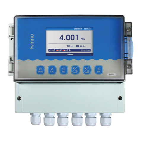
Twinno T6570 User manual

Twinno
Twinno T4046 User manual

Twinno
Twinno T4055 User manual

Twinno
Twinno T4050 User manual

Twinno
Twinno T6500 User manual

Twinno
Twinno T4000 User manual

Twinno
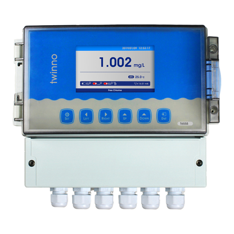
Twinno T6555 User manual

Twinno
Twinno T6055 User manual

Twinno
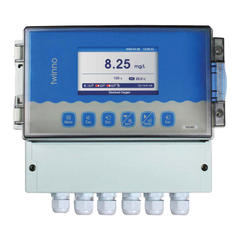
Twinno 16540 User manual
Popular Measuring Instrument manuals by other brands

Rohde & Schwarz
Rohde & Schwarz NRX Getting started

Ibiza
Ibiza LAS450RGB user manual

Major tech
Major tech MT790 instruction manual

Photon Systems Instruments
Photon Systems Instruments FluorPen FP 110 Manual and user guide

Chauvin Arnoux
Chauvin Arnoux MR6292 user manual

AXIOMA METERING UAB
AXIOMA METERING UAB QALCOSONIC E4 Technical operation guide