1110
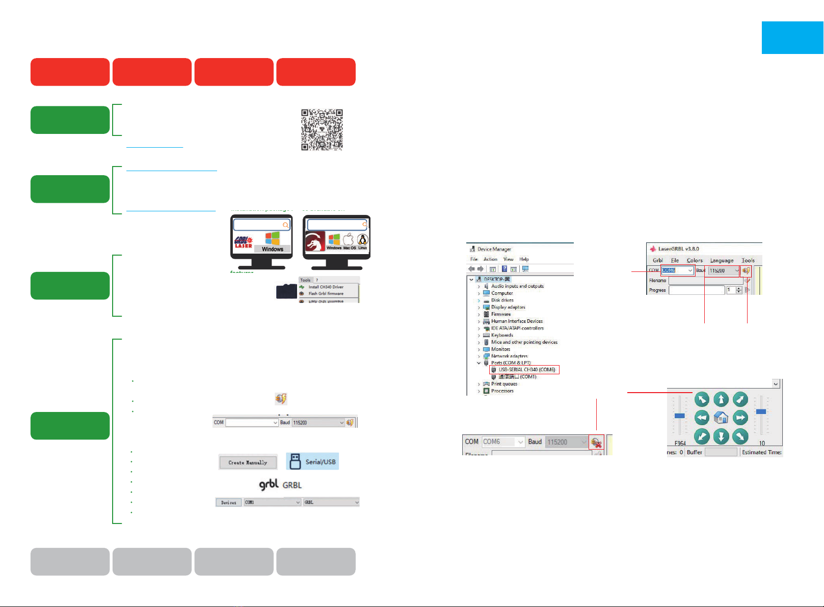
1. Connect the machine with the computer installed with LaserGRBL
software with USB data cable.
2. Plug in the power.
3. Open LaserGRBL on the computer.
4. Select the specific port number and baud rate——115200 (Figure A.10)
5. Click the lightning sign. When the lightning sign changes to the red “X”
and the direction sign is lit, it indicates that the connection is successful.
(Figure A.11)
Generally, the COM port does not need to be selected manually, unless
multiple serial port devices are connected to the computer, you can find the
port of the machine in the device manager of the windows system (as shown
in Figure A.09). A simpler way is to try the displayed port number one by one.
CONNECT PC
A.11
A.10
Successful
Choose the
correct port
Choose baud rate 115200 Lightning sign
Note:
If you cannot find the correct port in the “Ports”, you may need to
Method 1: Click "Tools" in the menu to install CH340 driver (This function is
not available in some software versions);
Method 2: Copy the "CH340ser. Exe" file in the TF Card (USB flash disk) to the
computer and install it.
EN
Driver Name: CH340SER.EXE
Where is the program?
1. The TF card attached by the manufacturer.
Search: CH340SER
2. Open the LaserGRBL software on your computer
The "Tools" menu of the LaserGRBL software.
LightBurn is a paid software, only 30 days for free.
https://lightburnsoftware.com/ (The installation package is also available on
the TF card from the manufacturer)
LightBurn For Windows, MAC
HOW TO START ?
Engraving Learning Process!
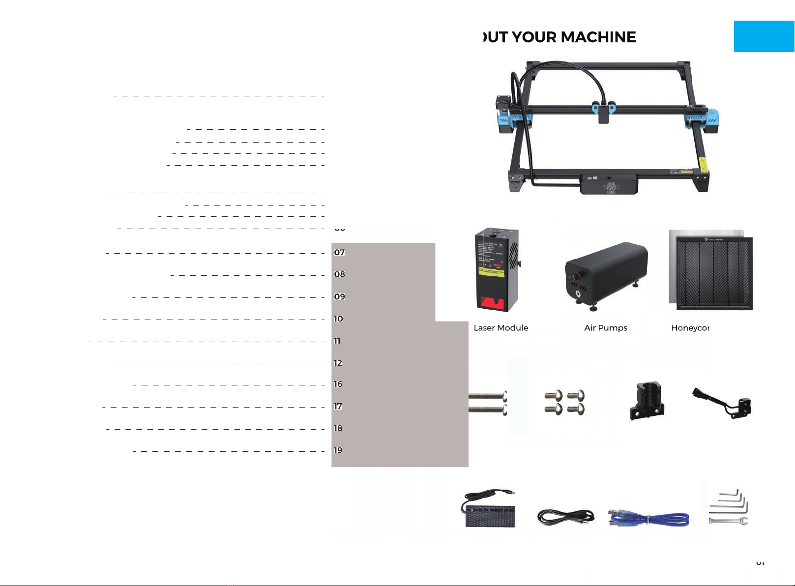
Assemble the machine
How to Assemble
the machine
How to Install
control software
How to Install
driver on computer
How to connect
the Machine &
the computer
Install the control
software on the
computer
Install the driver
on the computer Connect the machine
to the computer
Learn to use LaserGRBL
or lightburn.on websites
Learn to focus laser
via manual or video
Test speed and power
(Results for different
materials)
Communicate and share
via Facebook and YouTube
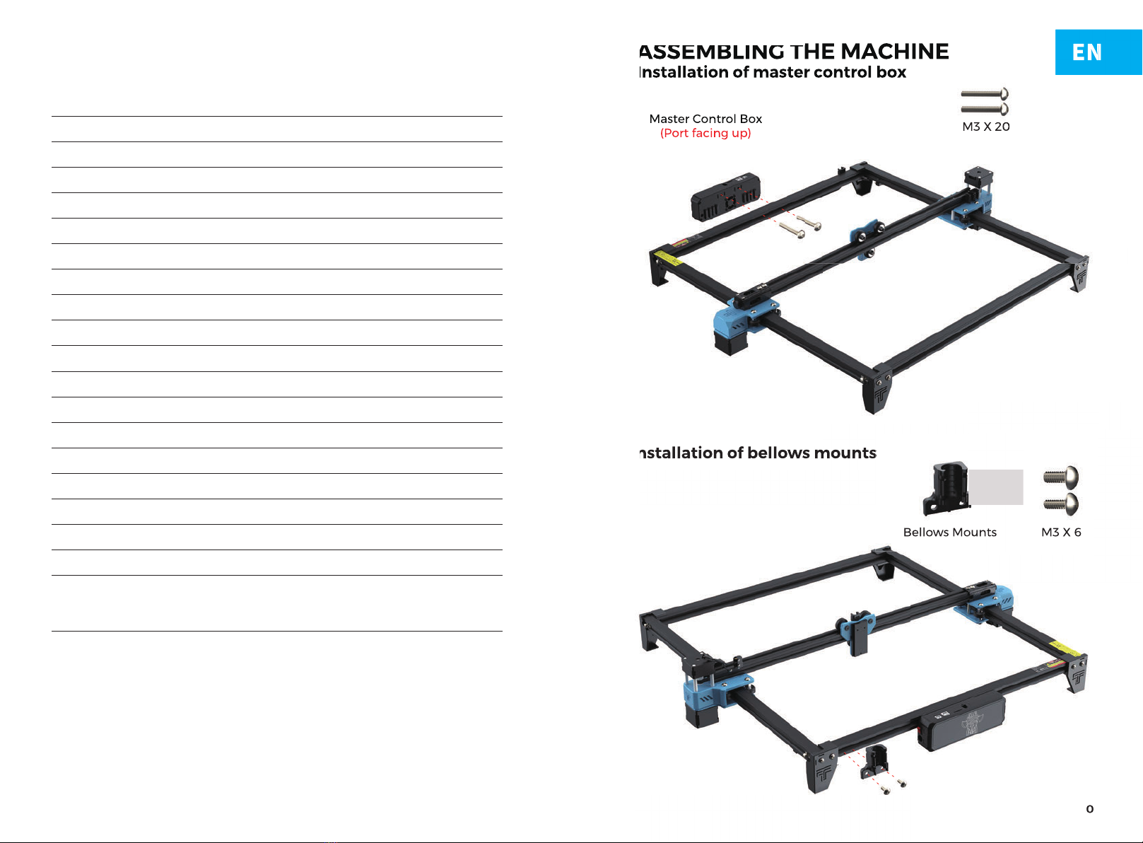
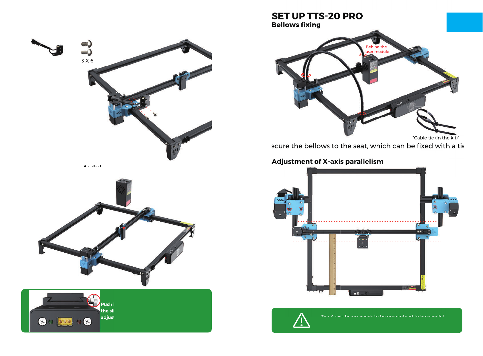
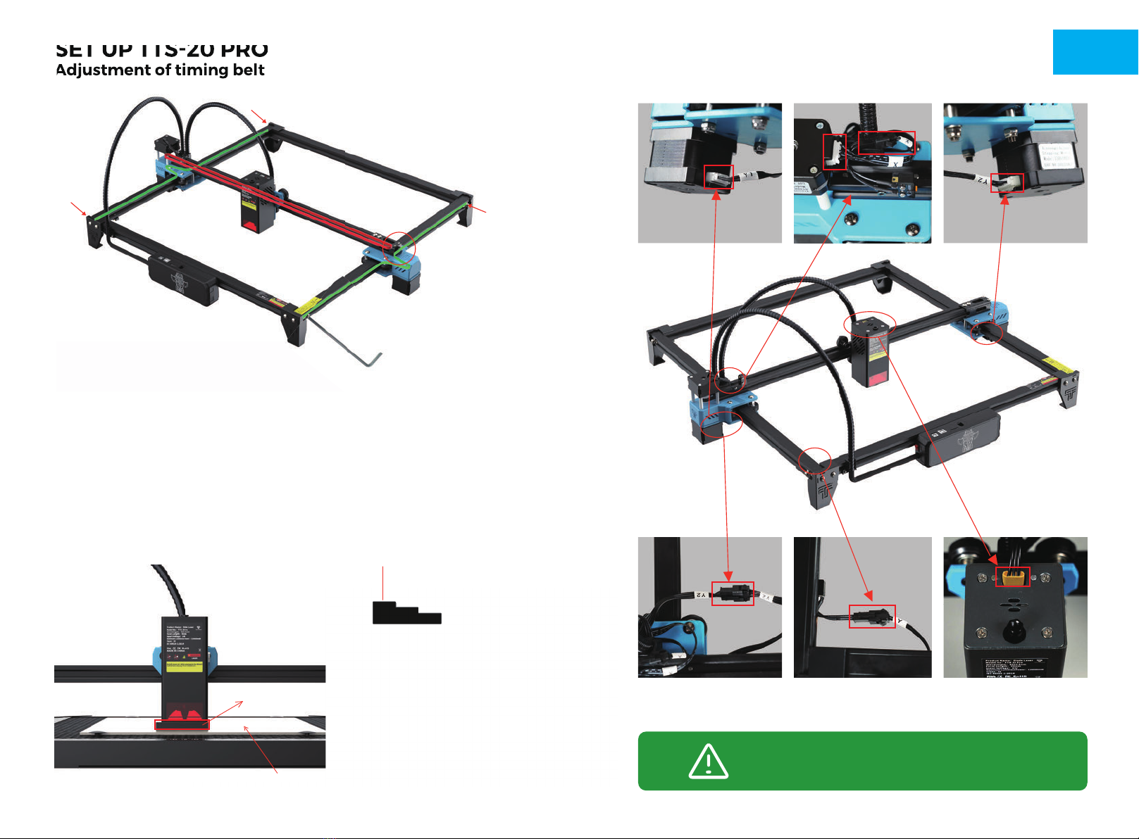
1. Read the product manual in detail and follow the steps in the manual
to assemble the machine.
2. Tutorial Video Watch it on Youtube!
www.youtube.com Search : TWO TREES Official
Note: Install the driver unsuccessfully will cause the computer to fail to connect
to the machine
Operating steps:
1. Turn on the machine.
2. Connect the machine to the computer with the USB cable.
3. Open LaserGRBL software
In the COM checkbox, choose the COM number of the machine. (usually not
COM1)
In the Baud checkbox, choose 115200.
Click on the "Connect" button to connect successfully.
(detailed operation)
Please check the back of the manual for
4. Open LightBurn software(Activated)
Choose “Create manually” .
Choose “GRBL” ,NEXT.
Choose “Serial/USB” .
Set the length of the working area.
Set Origin: Front left.
Turn off auto "home“, NEXT.
In the COM checkbox, choose the COM number of the
machine. (usually not COM1, MAC not showing COM)
Downloaded in LaserGRBL website, it's free.
http://lasergrbl.com/download/ (The installation package is also available on
the TF card from the manufacturer)
LaserGRBL For Windows
Watch video
"Connect" button
1. The TF card attached by the manufacturer.
(The installation package is also available on
lasergrbl.com
(The installation package is also available on
lightburnso�ware.com