Vision 5 Series User manual

© 2020 Vision Engraving & Routing Systems
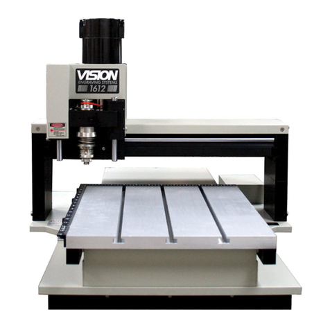
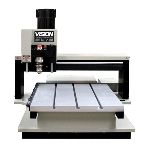
Vision 1612, 1624, 2424 and 2448
Series 5 Installation Guide
Revised: 5/14/2020Part number 12-1087-01
This is ONLY the Installation Guide.
PLEASE review the complete User
Manual for your machine, which will be
installed on your computer after the
software installation is completed.
Red Dot Laser Pointer Offset
X__________ Inches__ mm__
Y__________ Inches__ mm__
Braille Inserter Offset
X__________ Inches__ mm__
Y__________ Inches__ mm__
Factory Settings

All rights reserved. No parts of this work may be reproduced in any form or by any means - graphic, electronic, or
mechanical, including photocopying, recording, taping, or information storage and retrieval systems - without the
written permission of the publisher.
Products that are referred to in this document may be either trademarks and/or registered trademarks of the
respective owners. The publisher and the author make no claim to these trademarks.
While every precaution has been taken in the preparation of this document, the publisher and the author assume no
responsibilityfor errors or omissions, or for damages resulting from the use of information contained in this
document or from the use of programs and source code that mayaccompany it. In no event shall the publisher and
the author be liable for any loss of profit or anyother commercial damage caused or alleged to have been caused
directly or indirectly bythis document.
Revised: 5/14/2020
Vision 1612, 1624, 2424 and 2448 Series 5 Installation Guide
© 2020 Vision Engraving & Routing Systems

3Contents
3
© 2020 Vision Engraving & Routing Systems
Table of Contents
Part I Introduction 4
................................................................................................................................... 41 Computer Requirements
................................................................................................................................... 52 Vision Software Security Device
................................................................................................................................... 63 General Electrical and Facility Requirements
Part II Machine Setup 7
................................................................................................................................... 71 Locating the Engraver
................................................................................................................................... 82 Installation Layout Diagrams
.......................................................................................................................................................... 81612 and 1624 Engraver Layout Diagram
.......................................................................................................................................................... 92424 and 2448 Engraver Layout Diagram
................................................................................................................................... 103 Connections
................................................................................................................................... 134 Pendant Holder Installation
................................................................................................................................... 155 Spindle Options
.......................................................................................................................................................... 15NSK 50,000 RPM Spindle
.......................................................................................................................................................... 17UNIST Misting System
................................................................................................................................... 196 Network Connection
................................................................................................................................... 257 Vision Mov UI Software Installation
................................................................................................................................... 338 Vision Software Installation

Vision 1612, 1624, 2424 and 2448 Series 5 Installation Guide4
© 2020 Vision Engraving & Routing Systems
1 Introduction
This guide contains information to prepare the owner of a Vision 1612, 1624, 2424 or 2448 for the proper
installation of their machine. It is the customer's responsibility to read through this guide and make sure
the work area, electrical and computer requirements are met. If for any reason, there are questions about
these requirements, please call your Vision representative as soon as possible.
In the following sections, the complete machine and Vision software installation will be outlined.
Please call or email your Vision distributor or the Vision service department at Vision for assistance if
you have any questions with this procedure. The Vision service department phone number is 1-602-439-
0600 and the email address is service@visionengravers.com.
FOR MORE DETAILED INFORMATION, PLEASE REFER TO THE USER GUIDE FOR YOUR MACHINE
INSTALLED WITH THE VISION SOFTWARE. USER GUIDES ARE ALSO AVAILABLE ONLINE AT
http://www.visionengravers.com/support/vision-engraver-manuals.html
1.1 Computer Requirements
Minimum System
Requirements:
CPU:
Intel i5 2.6-3.0GHz
Hard Drive:
5 GB free space
RAM:
8 GB
Operating System:
Windows 10 (32/64 bit)
Windows 8 (32/64 bit)
Windows 7 (32/64 bit)
NOTE: Windows updates must ALL be installed
Ports:
1 USB port for security dongle
1 USB port for Ethernet adapter to connect machine
Suggested System
Requirements
CPU:
Intel i7 2.6-3.0GHz (or faster)
Hard Drive:
500 GB SSD (or larger)
RAM::
16 GB (or more)
Operating System:
Windows 10 (64 bit)
Ports
1 USB port for security dongle
1 USB port for Ethernet adapter to connect machine

Introduction 5
© 2020 Vision Engraving & Routing Systems
1.2 Vision Software Security Device
IMPORTANT:
The Vision software is available in two versions; one with a USB dongle, and one that is "dongleless" and
is loaded on to a USB Memory stick. If your machine was delivered with, or you currently have the silver,
white/blue or orange software dongle, DO NOT LOSE IT!
The Vision software will NOT run without the dongle plugged into the computer.

Vision 1612, 1624, 2424 and 2448 Series 5 Installation Guide6
© 2020 Vision Engraving & Routing Systems
1.3 General Electrical and Facility Requirements
Machine Model
Requirements
Vision 1612, 1624, 2424 or 2448
One 110 VAC 15 Amp
OR One 220 VAC 10 Amp Single Phase
Optional Equipment
Engraving Chip Removal System
Required in addition to the machine power above:
One 110 VAC 15 Amp OR One 220 VAC 10 Amp
Optional Equipment Requiring
Compressed Air Supply
UNIST Misting System
NSK 50,000 RPM Spindle
Required in addition to the machine power above:
Clean Dry Compressed Air Supply 60 - 90 PSI
One 110 VAC 15 Amp OR One 220 VAC 10 Amp Single
Phase AND Clean Dry Compressed Air Supply 1 SCFM
@ 40 PSI
NOTE: In addition to the above requirements, a standard outlet is required for the computer.

Introduction 7
© 2020 Vision Engraving & Routing Systems
2 Machine Setup
2.1 Locating the Engraver
1. Locate all equipment indoors on a flat surface and on a solid foundation.
2. Temperature must remain between 40°F and 85°F.
3. Do not expose machine to direct sunlight, rain, vibration, dampness, or explosive environments.
4. Machine dimensions:
1612 - 33” x 23” x 19”, shipping weight = 300 lbs.
1624 - 33” x 35” x 19”, shipping weight = 320 lbs.
2424 - 42” x 33” x 20”, shipping weight = 371 lbs.
2448 - 66” x 33” x 20”, shipping weight = 520 lbs.
NOTE: If you use our freight company, the equipment will be placed on the ground and a
pallet jack or other device is necessary to move the crate into your facility.
5. The sides of the crate unscrew, but it will take four people to remove the engraver from the
shipping crate.
6. A distance of at least 36" is recommended around all sides of the machine to ensure easy
operating, material handling, cleaning, maintenance and safety.
7. Typically, the engraver is oriented as shown in the layout diagrams.
8. Cutters and sample materials must be available before the scheduled installation/machine
orientation date.
9. If a chip extraction unit has not been purchased from Vision, it is highly recommended that one is
available for the installation/machine orientation.
10. If you ordered the NSK High Frequency Spindle, a clean air source is required. The air requirement
is 1 CFM @ 40 psi.

Vision 1612, 1624, 2424 and 2448 Series 5 Installation Guide8
© 2020 Vision Engraving & Routing Systems
2.2 Installation Layout Diagrams
2.2.1 1612 and 1624 Engraver Layout Diagram

Machine Setup 9
© 2020 Vision Engraving & Routing Systems
2.2.2 2424 and 2448 Engraver Layout Diagram

Vision 1612, 1624, 2424 and 2448 Series 5 Installation Guide10
© 2020 Vision Engraving & Routing Systems
2.3 Connections
On the rear of the Vision Series 5 controller, there are 13 connection ports. Plug in all of the cables
unless noted below.
1. The Aux Table plug connects to a 15 pin connector on the Vision 2424 and 2448. NOTE: This is not
used with the 1612 or 1624.
2. The Table plug connects to a 25 pin connector on the Vision 1612, 1624, 2424 and 2448.
3. The Rotary plug connects to a 9 pin connector on the Vision Rotary attachment. NOTE: This is not
used unless a rotary attachment is configured with the machine.
4. The 90V Spindle plug connects a 4 pin round connector that comes from the Vision 1612, 1624, 2424
and 2448.
5. The Vacuum plug connects to a 2 pin round connector that comes from an optional vacuum chip
removal system. If your machine is equipped with the optional Vacuum Chip Removal System, a
remote On/Off cable is connected from the controller to automatically turn the vacuum pump on and
off when the job is being run. NOTE: This will not be used if a vacuum chip removal system is not
configured with the machine.
6. The Pump/Mist plug connects to a misting system or water pump. NOTE: This is not used unless a
misting system or water pump is configured with the machine.
7. The Computer plug connects to the Ethernet port on the computer. This is typically plugged into the
USB to Ethernet adapter supplied with the machine.
8. The Pendant network plug connects to the back of the touch screen LCD pendant.
9. The 4 pin Pendant plug connects to the back of the touch screen LCD pendant.
10. The Mod Bus plug connects to the 3 hp router spindle power inverter. NOTE: This is only used if the
3 hp router motor is configured with the machine.
11. The power input plug connects to either the power source. IMPORTANT: Only use the 110 volt AC
or 220 volt AC power source that is displayed on the yellow label. Using the incorrect input power
can cause serious damage to the machine.
12. The Analog plug is used to control optional spindles such as a 50,000 RPM spindle. NOTE: This is
not used unless an optional spindle is configured with the machine.
13. The Aux plug is an expansion port that can be used for new products at a later date. NOTE: This is
not currently used.
Machine Setup 11
© 2020 Vision Engraving & Routing Systems
Vision Series 5 controller (rear view)

Vision 1612, 1624, 2424 and 2448 Series 5 Installation Guide12
© 2020 Vision Engraving & Routing Systems
Vision Series 5 pendant (rear view)
NOTE: If the emergency stop screen appears on the LCD when the machine is powered on, then the
emergency stop button is pressed in. This can either be the emergency stop button on the table or the
emergency stop button on the pendant. Release the button twisting it until it "pops up". This will clear
the emergency stop screen.
The machine is now connected. Please continue to the network setup section.

Machine Setup 13
© 2020 Vision Engraving & Routing Systems
2.4 Pendant Holder Installation
The 2424 and 2448 machines are shipped with a Pendant Holder to give the user a place to secure the
Pendant.
NOTE: Not required for 1612 or 1624.
To install the Pendant Holder on the 25 Series machines, follow the below procedure.

Vision 1612, 1624, 2424 and 2448 Series 5 Installation Guide14
© 2020 Vision Engraving & Routing Systems

Machine Setup 15
© 2020 Vision Engraving & Routing Systems
2.5 Spindle Options
2.5.1 NSK 50,000 RPM Spindle
The NSK Spindle mounts in place of the standard spindle to the Router Rail Plate in the same location
as other Router or Engraving Head Assemblies. Two dowel pins are pressed into the Mounting Bracket
Assembly and four mounting screws secure the bracket to the rail plate.
Electrical Connections
If the machine was ordered with the NSK Spindle option, an Analog Spindle port was installed on the
machine's controller. Connect the Analog Spindle Cable to this port on the controller and the other end to
the Analog Spindle Port on the NSK Power Supply Unit (The Analog Spindle Cable is identical to the
Table Cable used to connect the controller to the engraver or router's table. Be careful not to connect
the Table port on the controller to the Analog Spindle Port on the NSK Power Supply Unit).

Vision 1612, 1624, 2424 and 2448 Series 5 Installation Guide16
© 2020 Vision Engraving & Routing Systems
Connect the Power Cable to a standard 110 VAC power outlet and to the NSK Power Supply Unit. The
cable assembly coming from the NSK Spindle has a connector to the spindle motor and an air hose. The
motor connector is plugged into the Motor port and the air hose is connected to the AIR OUT port on the
NSK Power Supply.
The NSK Spindle requires an external compressed air supply capable of 1 SCFM @ 40 PSI. The air
supply is connected via the Inlet Air Hose to the AIR IN port on the NSK Power Supply Unit.
NOTE: The Spindle Cable to the standard engraving motor will not be used in this configuration.
Installing Cutting Tools
The NSK Spindle can accept either 1/8" or 1/4" cutting tools., depending on which collet was shipped
with the system. The spindle will accept standard 2" shank bottom loading cutting tools. The collar at the
bottom of spindle and the spindle shaft both have flat areas (tool slots) to allow the user to loosen or
tighten the collet. Special thin wrenches are shipped with the NSK Spindle for this purpose.

Machine Setup 17
© 2020 Vision Engraving & Routing Systems
2.5.2 UNIST Misting System
The optional UNIST Misting System is designed to provide lubrication to the cutting tool and material
when processing metals. The diagram shown below lists the main components and connections. This
system requires a compressed air supply (60 PSI Max) to be connected to the inlet air line.
Documentation for usage of the UNIST Misting System is included with the system. Please refer to this
documentation for operation details.

Vision 1612, 1624, 2424 and 2448 Series 5 Installation Guide18
© 2020 Vision Engraving & Routing Systems

Machine Setup 19
© 2020 Vision Engraving & Routing Systems
Additionally, the Misting System Power Plug on the machine connects to the controller's Pump/Mist port
with the supplied cable.
2.6 Network Connection
NOTE - This following section is shown on a Windows 10 PC. For Windows 7 or Windows 8, the screens
are slightly different.
Plug the USB end of the USB to Ethernet adapter into any open USB port on the computer.

Vision 1612, 1624, 2424 and 2448 Series 5 Installation Guide20
© 2020 Vision Engraving & Routing Systems
Right click on the Windows network icon in the lower right corner of the Windows screen.
Select "Open Network & Internet settings".
Other manuals for 5 Series
1
This manual suits for next models
4
Table of contents
Other Vision Engraver manuals

Vision
Vision Multi Axis User manual

Vision
Vision MaxPro User manual

Vision
Vision PHOENIX TABLE User manual

Vision
Vision 1612 User manual

Vision
Vision MAX Pro User manual

Vision
Vision Express S5 User manual

Vision
Vision 16 Series User manual

Vision
Vision VE-810 User manual

Vision
Vision Phoenix 1212 S5 User manual

Vision
Vision VE810 S5 User manual