TYAN Tempest i5100T User manual

1
Tempest i5100T /// S5377
Version 1.0
Copyright
Copyright © TYAN Computer Corporation, 2007. All rights reserved. No part of
this manual may be reproduced or translated without prior written consent from
TYAN Computer Corp.
Trademark
All registered and unregistered trademarks and company names contained in
this manual are property of their respective owners including, but not limited to
the following.
TYAN, Tempest i5100T are trademarks of TYAN Computer Corporation.
Intel® 5100/5200/5400 Series and combinations thereof are trademarks of Intel
Corporation.
AMI, AMI BIOS are trademarks of AMI Technologies.
Microsoft, Windows are trademarks of Microsoft Corporation.
SuSE is a trademark of Novell.
IBM, PC, AT, and PS/2 are trademarks of IBM Corporation.
Notice
Information contained in this document is furnished by TYAN Computer
Corporation and has been reviewed for accuracy and reliability prior to printing.
TYAN assumes no liability whatsoever, and disclaims any express or implied
warranty, relating to sale and/or use of TYAN products including liability or
warranties relating to fitness for a particular purpose or merchantability. TYAN
retains the right to make changes to product descriptions and/or specifications
at any time, without notice. In no event will TYAN be held liable for any direct or
indirect, incidental or consequential damage, loss of use, loss of data or other
malady resulting from errors or inaccuracies of information contained in this
document.

2
Table of Contents
Check the box contents! 3
Chapter 1: Introduction
1.1 Congratulations 5
1.2 Hardware Specifications 5
Chapter 2: Board Installation
2.1 Board Image 8
2.2 Block Diagram 9
2.3 Board Parts, Jumpers and Connectors 10
2.4 Tips on Installing Motherboard in Chassis 17
2.5 Installing the Processor(s) 18
2.6 Installing the Memory 21
2.7 Attaching Drive Cables 23
2.8 Installing Add-in Cards 24
2.9 Installing Optional SO-DIMM Modules 25
2.10 Connecting External Devices 26
2.11 Installing the Power Supply 27
2.12 Finishing up 27
Chapter 3: BIOS Setup
3.1 About the BIOS 28
3.2 BIOS Menu Bar 28
3.3 Setup Basics 29
3.4 Getting Help 29
3.5 In Case of Problems 29
3.6 BIOS Main Menu 30
3.7 Advanced Menu 31
3.8 PCI PnP Menu 51
3.9 Boot Menu 53
3.10 Security Menu 57
3.6 Chipset Menu 58
3.7 Exit Menu 62
Chapter 4: Diagnostics
4.1 Beep Codes 64
4.2 Flash Utility 64
4.3 AMI BIOS Post Code 65
Appendix: SMDC Information 68
Glossary 70
Technical Support 76

3
Check the box contents!
1 x TYAN Driver CD
1 x User’s Manual, V1.0, S5377
1 x Quick Reference, V1.0, S5377
1 x PWR Adapter Cabe
2 x Serial ATA Power Cable
4 x Serial ATA Cable
1 x USB2.0 Cable
1 x CPU Back Plane
If any of these items are missing, please contact your vendor/dealer for
replacement before continuing with the installation process.

4
NOTE

5
Chapter 1: Introduction
1.1 - Congratulations
You have purchased one of the most powerful server solutions. The Tempest
i5100T (S5377) is a flexible Intel®platform for multiple applications, based on
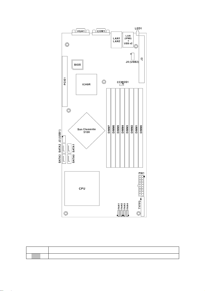
Intel®5100 MCH (San Clemente) and ICH9R chipsets.
Designed to support dual core Intel®Xeon®, and 32GB DDR2-533/667 DIMM
memory, and featured with integrated 82571EB dual port LAN controllers, built-
in 32MB XGI Z9S video plus four SATA2 ports, the S5377 offers exceptional
performance and versatile solution for your server / Workstation.
Remember to visit TYAN’s Website at http://www.TYAN.com. There you can
find information on all of TYAN’s products with FAQs, online manuals and BIOS
upgrades.
1.2 - Hardware Specifications
Processors
•One LGA771 socket
•Supports Intel® 5100/5200/5400
processors
•Supports 1.33 / 1.06 GHz FSB
Memory
•Eight (8) DIMM sockets
•Supports Registered ECC DIMMs
•Single & Dual Rank, Maximum 4
Ranks/Channel
•Single/Dual channel support
•Supports 256Mb, 512Mb, 1Gb, 2Gb,
and 4Gb memory modules.
•Maximum of 32GB of DDR2 DIMM
533/667
System Management
•Four (4) fan headers (8-pin) with
control and tachometer monitoring
•Monitors voltage for CPU,
environment
•Supports Serial Console Redirect
•Supports Watch Dog Timer
•IPMI 2.0 supported
Integrated Serial ATA II (ICH9-R)
Chipset
•Intel®5100 Chipset (San Clemente)
North Bridge
•Intel®ICH9-R South Bridge
•Winbond 83627DHG Super I/O chip
Expansion Slots
•One (1) PCI-E x16 slot
Internal I/O Interfaces
•One 200-pin SO-DIMM socket for
server management (M3295/M3296)
•Two USB pin-header to support USB
DOM and two USB 2.0 devices
•Tyan FPIO to support NMI SM-Bus,
Chassis Intrusion
Graphics
•XGI Z9S, PCI graphics controller
•32MB DDR2 frame buffer of video
memory
LAN Controllers
•One Intel 82571EB dual port Gigabit
controllers to support two GbE ports

6
•Supports four Serial ATA ports
running up to 3.0Gb/s
•Software RAID Levels 0, 1, 5, 10
supported
Back Panel I/O Ports
•One serial port with D-Sub connector
•One staked dual USB ports with One
RJ45 port (supports M3295-2/M3296
IPMI from LAN)
•One stacked up LAN ports with dual
RJ45 connectors with Transformer &
LEDs
•One 9-pin COM port
•One 15-pin VGA port
•One ID LED
BIOS
•AMI BIOS on 8Mbit Flash ROM
•Supports ACPI 2.0
•Supports boot from USB device
•WOL and PXE support
•Power-on mode control for AC power
loss recovery
•PnP, DMI2.0, WfM2.0 Power
management (S1, S4, S5 support)
Form Factor
•Proprietary (5.9” x 13”)
Power
•Onboard VRD 11.0
•Proprietary 18-pin power connectors
Regulatory
•FCC Class A (DoC)
•European Community CE (DoC)
•VCCI
•C-Tick

7
Chapter 2: Board Installation
You are now ready to install your motherboard. The mounting hole pattern of
the Tempest i5100T S5377 matches the proprietary form factor (5.9” x 13”).
Before continuing with installation, confirm that your chassis supports a
proprietary 5.9” x 13” motherboard.
How to install our products right… the first time
The first thing you should do is reading this user’s manual. It contains important
information that will make configuration and setup much easier. Here are some
precautions you should take when installing your motherboard:
(1) Ground yourself properly before removing your motherboard from the
antistatic bag. Unplug the power from your computer power supply and
then touch a safely grounded object to release static charge (i.e. power
supply case). For the safest conditions, TYAN recommends wearing a
static safety wrist strap.
(2) Hold the motherboard by its edges and do not touch the bottom of the
board, or flex the board in any way.
(3) Avoid touching the motherboard components, IC chips, connectors,
memory modules, and leads.
(4) Place the motherboard on a grounded antistatic surface or on the
antistatic bag that the board was shipped in.
(5) Inspect the board for damage.
The following pages include details on how to install your motherboard into your
chassis, as well as installing the processor, memory, disk drives and cables.
NOTE DO NOT APPLY POWER TO THE BOARD IF IT HAS BEEN
DAMAGED.

8
2.1- Board Image
This picture is representative of the latest board revision available at
the time of publishing. The board you receive may or may not look
exactly like the above picture.

9
2.2 - Block Diagram
Tempest i5100T S5377 Block Diagram

10
2.3 - Board Parts, Jumpers and Connectors
This diagram is representative of the latest board revision available at the time of
publishing. The board you receive may not look exactly like the above diagram.
Jumper Legend
OPEN - Jumper OFF, without jumper cover
CLOSED – Jumper ON, with jumper cover

11
Jumper/Connector Function
J2 USB1, USB Front Panel Header
J4 USB2, USB Header
J3 IPMI Connector
CCMOS 1 Clear CMOS Jumper
SATA0~SATA3 Serial ATA RAID Connector
FAN1/FAN2/FAN3/FAN4 8-pin FAN Connector with Speed Control
J5 TYFP3, Front Panel Header

12
SATA0/1/2/3: Serial ATA RAID Connector
1
7
Connects to the Serial ATA ready drives via the Serial
ATA cable.
Pin Signal
1 GND
2 TX+
3 TX-
4 GND
5 RX-
6 RX+
7 GND
SATA0
SATA1
SATA2
SATA3

13
J5
J
4
J2

14
J5: TYFP3 Connector Front Panel Header
27 28
12
Use this header to connect some control or signal wires
from motherboard to chassis, such as HDD LED, power
LED, power button, and reset button.
Pin Signal Pin Signal
1 HD_LED+ 2 HD_LED-
3 RESET+ 4 RESET-
5 PWR_LED+ 6 PWR_LED-
7 WLED+ 8 WLED-
9 SMBDAT 10 SMBCLK
11 EXT_INT 12 +5V
13 5VSB 14 INTRUDER_N
15 PWR_SW+ 16 PWR_SW-
17 LAN1_LED+ 18 LAN1_LED-
19 LAN2_LED+ 20 LAN2_LED-
21 LAN3_LED+ 22 LAN3_LED-
23 ID_LED+ 24 ID_LED-
25 ID_SW+ 26 ID_SW-
27 Key 28 RSV
J2/J4: USB Front Panel Header (USB1) /USB Header (USB2)
1
910
2
Each USB header supports 2 additional USB ports.
Use these headers to connect the PCI USB bracket or
internal USB header cable to the front or rear I/O.
Pin Signal Pin Signal
1 +5V 2 +5V
3 USB_P0_N 4 USB_P1_N
5 USB_P0_P 6 USB_P1_P
7 GND 8 GND
9 Key 10
RSV

15
CCMOS1
FAN1/ FAN2/ FAN3 /FAN4

16
FAN1/ FAN2/ FAN3/ FAN4: 8-pin Fan Connector
1
Use this header to connect the cooling fan to your
motherboard to keep the system at optimum
performance levels.
Pin Signal
1 FAN_PWM1
2 +12V
3 FAN_TACH1
4 GND
5 GND
6 FAN_TACH2
7 +12V
8 FAN_PWM2
CCMOS1: Clear CMOS Jumper
31
Normal
(Default)
31
Clear
Use this jumper when you forgot your system/setup
password or need to clear system BIOS setting.
How to clear the CMOS data
- Power off system and disconnect power
supply from AC source
- Use jumper cap to close Pin_2 and 3 for
several seconds to Clear CMOS
- Replace jumper cap to close Pin_1 and 2
Reconnect power supply to AC source
- Power on system

17
2.4 - Tips on Installing Motherboard in Chassis
Before installing your motherboard, make sure your chassis has the
necessary motherboard support studs installed. These studs are usually
metal and are gold in color. Usually, the chassis manufacturer will pre-install
the support studs. If you are unsure of stud placement, simply lay the
motherboard inside the chassis and align the screw holes of the
motherboard to the studs inside the case. If there are any studs missing,
you will know right away since the motherboard will not be able to be
securely installed.
Some chassis’ include plastic studs instead of metal. Although the plastic
studs are usable, TYAN recommends using metal studs with screws that will
fasten the motherboard more securely in place.
Below is a chart detailing what the most common motherboard studs look
like and how they should be installed.

18
2.5 - Installing the Processor(s)
Your Tempest i5100T S5377 supports the latest processor technologies from
Intel. Check the TYAN website for latest processor support:
http://www.tyan.com
Processor Installation (LGA771 Socket)
The processor should be installed carefully. Make sure you are wearing an
antistatic strap and handle the processor as little as possible. Please note that
both processors of the same type and frequency are required for optimal
system performance.
Follow these instructions to install your processor.
1. Locate the processor socket on the motherboard and lift the protective
cover off as shown.
WARNING:
This new processor socket
designed by Intel is easy to be
damaged. The processor has to be
installed very carefully to prevent
the contact pins of the socket from
breaking. It is strongly
recommended the processor
installation job to be handled by the
experienced technician.
2. Pull the locking lever out of it’s locked position and let it spring into the
open position.

19
3. Lift the metal cover to expose the socket interior and place the CPU in as
shown.
4. Close the cover and return the locking lever to its locked position.
Heatsink Installation
After you have installed the processor, the heatsink should be installed to
ensure that the processor runs efficiently and does not overheat. Use the
heatsink supplied for best results.
Follow these instructions to install the heatsink shown.
1. Take out the heatsink from the package. Turn the heatsink upside down
and you can see that the heatsink has already applied a layer of thermal
compound.
2. Turn the board upside down and insert the heat sink spring mechanism
as shown.
Pin 1

20
3. Turn the board the right way up again and align the heatsink with the four
holes around the processor socket.
4. Press the heatsink down until the four screws are securely seated in the
holes.
5. Use screwdriver to secure the four screws.
CPU VRD Heat Dispersion Notice
INSTALL FAN INTO CHASSIS TO LET AIR FLOW IN!!!
-To ensure that the board runs efficiently and does not overheat, make sure
there is air flow around the CPU VRD (as shown) to help disperse the heat
generated around the CPU.
CPU VRD
This manual suits for next models
1
Table of contents
Other TYAN Motherboard manuals

TYAN
TYAN TOMCAT K8E-SLI User manual

TYAN
TYAN S7070 User manual

TYAN
TYAN S8005 User manual

TYAN
TYAN TAHOE PLUS ATX User manual

TYAN
TYAN Tiger MP S2460 User manual

TYAN
TYAN M4985 User manual

TYAN
TYAN S7063 User manual

TYAN
TYAN TOMAHAWK BX User manual

TYAN
TYAN S5501 Operation and maintenance manual

TYAN
TYAN TITAN TURBO AT User manual

TYAN
TYAN THUNDER K7 User manual

TYAN
TYAN S5552 User manual

TYAN
TYAN 1.00 User manual

TYAN
TYAN Tempest i5000VS S5372-LC User manual

TYAN
TYAN THUNDER K8QS User manual

TYAN
TYAN S5512 User manual

TYAN
TYAN THUNDER K8HR User manual

TYAN
TYAN THUNDER 2400 User manual

TYAN
TYAN THUNDER I7501 XTREME User manual

TYAN
TYAN S7076 User manual