TYAN Thunder n6550EX User manual

Thunder n6550EX S4989
Version 1.2
Copyright
Copyright © MiTAC International Corporation, 2008. All rights reserved. No part
of this manual may be reproduced
or translated without prior written consent from MiTAC International Corporation.
Trademark
All registered and unregistered trademarks and company names contained in
this manual are property of their respective owners including, but not limited to
the following.
TYAN®, Thunder n6550EX are trademarks of MiTAC International Corporation.
AMD®,Opteron™, and combinations thereof are trademarks of AMD
Corporation.
AMI®, AMIBIOS®, and combinations thereof are trademarks of AMI
Technologies.
Microsoft®, Windows®are trademarks of Microsoft Corporation.
Nvidia®and nForce®are trademarks of Nvidia Corporation.
IBM®, PC®, AT®, PS/2®are trademarks of IBM Corporation.
Winbond®is a trademark of Winbond Electronics Corporation.
Notice
Information contained in this document is furnished by MiTAC International
Corporation and has been reviewed for accuracy and reliability prior to printing.
MiTAC assumes no liability whatsoever, and disclaims any express or implied
warranty, relating to sale and/or use of TYAN®products including liability or
warranties relating to fitness for a particular purpose or merchantability. MiTAC
retains the right to make changes to product descriptions and/or specifications
at any time, without notice. In no event will MiTAC be held liable for any direct
or indirect, incidental or consequential damage, loss of use, loss of data or other
malady resulting from errors or inaccuracies of information contained in this
document.

II
http://www.tyan.com

Contents
Before you begin Ⅴ
Chapter 1: Instruction 1
1.1 Congratulations .......................................................................................1
1.2 Hardware Specifications.......................................................................... 1
1.3 Software Specifications ...........................................................................2
Chapter 2: Board Installation 3
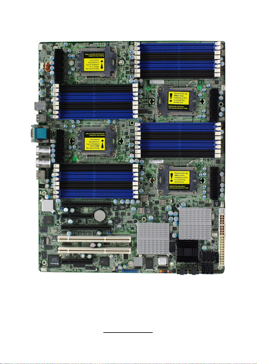
2.1 Board Image ............................................................................................4
2.2 Block Diagram .........................................................................................5
2.3 Board Parts, Jumpers and Connectors....................................................6
2.4 Installing the Processor .........................................................................14
2.5 Heat sink Installation .............................................................................15
2.6 Thermal Interface Material.....................................................................16
2.7 Finishing Installing the Heat sink ........................................................... 17
2.8 Tips on Installing Motherboard in Chassis.............................................18
2.9 Installing the Memory ............................................................................ 20
2.10 Attaching Drive Cables ........................................................................23
2.11 Installing Add-In Cards ........................................................................24
2.12 Connecting External Devices............................................................... 25
2.13 Installing the Power Supply .................................................................26
2.14 Finishing Up.........................................................................................27
Chapter 3: KVM-over-IP Server Management 29
3.1 Overview of KVM-over-IP Sever Management ......................................29
3.2 Key Feature ...........................................................................................29
3.3 Initialize and Web Interface .................................................................. 30
3.4 Configuration ........................................................................................33
3.5 Menu Option .........................................................................................40
Chapter 4: BIOS Setup 81
4.1 About the BIOS..................................................................................... 81
4.2 BIOS Menu Bar ....................................................................................81
4.3 Setup Basics......................................................................................... 82
4.4 Getting Help..........................................................................................82
4.5 In Case of Problems ............................................................................. 82
4.6 BIOS Main Menu ..................................................................................83
4.7 BIOS Advanced Menu ..........................................................................84
4.8 PCI PnP Menu.................................................................................... 104
4.9 Boot Menu ..........................................................................................106
4.10 Security Menu....................................................................................111
4.11 Chipset Menu ....................................................................................112
4.12 Exit Menu........................................................................................... 125
III
http://www.tyan.com

Chapter 5: Diagnostics 127
5.1 Beep Codes......................................................................................... 127
5.2 Flash Utility .......................................................................................... 127
5.3 AMIBIOS Post Code............................................................................ 128
Appendix: How to Make a Driver Diskette 131
Glossary 133
Technical Support 139
IV
http://www.tyan.com

http://www.tyan.com
V
Before you begin…
Check the box contents!
The retail motherboard package should contain the following:
1x S4989-SI Motherboard
6 x SATA Cable
2 x SAS to Backplane Cable
4 x CPU backplane
1 x S4989 User’s manual
1 x S4989 Quick reference guide
1 x TYAN®Driver CD
1 x I/O shield

VI
http://www.tyan.com

1
http://www.tyan.com
Chapter 1: Instruction
1.1 - Congratulations
You have purchased one of the most powerful server solutions. Based on
NVIDIA®NPF3600 and NPF3050 chipsets, the Thunder n6650EX (S4989) is
designed to support AMD®Opteron™ Rev. F 8000 series Dual-core and Quad-
core processors and up to 256GB DDR2-400/533/667, 128GB DDR2-800
memory, providing a rich feature set and incredible performance. Leveraging
advanced technology from AMD®, the Thunder n6650EX (S4989) is capable of
offering scalable 32 and 64-bit computing, high-bandwidth memory design, and
lightning-fast PCI-E, PCI-X bus implementation.
The Thunder n6650EX (S4989) not only empowers your company in today’s
demanding IT environment but also offers a smooth path for future application
usage. TYAN®is also proud to deliver the Thunder n6650EX (S4989) in SAS
and SATA II flavor. All of this provides the Thunder n6650EX (S4989) the power
and flexibility to meet the needs of nearly any server application.
Remember to visit TYAN®’s Website at http://www.tyan.com. There you can find
information on all of TYAN®’s products with FAQs, online manuals and BIOS
upgrades.
1.2 - Hardware Specifications
Processors
●Four 1207-pin ZIF socket
●Support up to four AMD®Opteron™
Rev. F 8000 series Dual-
Core/Quad-Core processors
●Support up to 4.4GT/s Hyper
Transport TM inter-processor link
●Four onboard 5-phase VRDs (four
phases for CPU-core and one
phase for North bridge)
Chipset
●NVIDIA®nForce®Pro 3600
NVIDIA®nForce®Pro 3050
●PERICOM®PI7C9X130 PCI-E
bridge
●HW monitors:
(1) Winbond W83793G
(2) ADT7476
●Super I/O:
Winbond W83627HG-AW
Expansion Slots
●(2) PCI-E slots with x16 signal
(1) x 16 signal from MCP55
(1) x 8 or x16 signal (through
PCI-E switch) from IO55
●(2) PCI-E slots with x8 signal
from IO55
●(2) PCI-X 133MHz slots from
PERICOM® PI7C9X130 (through
IO55)
System Management
●Raritan KIRA100 chip w/ iKVM
(M3 type)
Onboard SAS Controller
●LSISAS1068E SAS controller
●(8) SAS ports
●RAID 0,1,1E support

2
http://www.tyan.com
Memory
●128-bit Dual-channel memory bus
●(32) 240-pin1.8-volt DDR2 DIMM
slots (eight on each CPU)
●Support memory speeds of
400/533/667/800^MHz
●Supports up to 256GB of ECC
Registered DDR2 memory
●Supports Single and Dual Rank*
memory
^ 800MHz DDR2 speed support available
only at 4xDIMM’s per CPU or less
* (8) Dual Rank memory per CPU will have a
maximum memory speed of 533MHz
Integrated I/O
●(2) USB headers (two ports in one
header)
●(6) SATAII connectors from
MCP55 (one is for CD-ROM)
●(8) SAS ports (two four-in-one
connectors) from LSISAS1068E
●(2) RJ-45 10/100/1000 LAN ports
from Intel 82571EB
(1) RJ-45 10/100 LAN port from
onboard Raritan KIRA100 chip w/
iKVM
●(10) 4-pin FAN headers with autofan
and tachmeter function
●(1) 2x9-pin front panel header
●(1) 2x6-pin TYFP2 header
●(1) 2x9-pin FAN header for
Barebone
●(1) 2x3-pin LCM header
Back Panel I/O Connector
●Stacked connector for PS/2®
keyboard and mouse
●Stacked connector for (2) USB 2.0
●Stacked connector for VGA+COM
●(3) RJ-45 connectors, side by side
Integrated Network Processor
●GbE Intel 82571EB (2x GbE
ports)
●Davicom DM9161 (PHY) for
onboard Raritan KIRA100 w/
iKVM (LAN3 MAC is integrated
in KIRA100)
●WOL and PXE support
●(3) RJ-45 ports with LEDs
Integrated 2D PCI Graphics
●XGI Volari™ Z9s
●PCI interface
●32MB DDR2 frame buffer
memory
BIOS
●AMIBIOS®on 8Mbit LPC Flash
ROM
Form Factor
●MEB (13”x 16.2”)
●PCB layer:10-layer
Power
●EPS12V
●(1) 24-pin,3V+5V+12V power
connector
●(2) 8-pin,12V power connector
●(1) 4-pin,12V power connector
Regulatory
●FCC Class B (DoC)
●European Community CE (DoC)
1.3 - Software Specifications
For OS (operation system) support, please check with Tyan support for latest
information.

3
http://www.tyan.com
Chapter 2: Board Installation
You are now ready to install your motherboard.
How to install our products right… the first time
The first thing you should do is reading this user’s manual. It contains important
information that will make configuration and setup much easier. Here are some
precautions you should take when installing your motherboard:
(1) Ground yourself properly before removing your motherboard from the
antistatic bag. Unplug the power from your computer power supply and
then touch a safely grounded object to release static charge (i.e. power
supply case). For the safest conditions, TYAN®recommends wearing
a static safety wrist strap.
(2) Hold the motherboard by its edges and do not touch the bottom of the
board, or flex the board in any way.
(3) Avoid touching the motherboard components, IC chips, connectors,
memory modules, and leads.
(4) Place the motherboard on a grounded antistatic surface or on the
antistatic bag that the board was shipped in.
(5) Inspect the board for damage.
The following pages include details on how to install your motherboard into your
chassis, as well as installing the processor, memory, disk drives and cables.
NOTE DO NOT APPLY POWER TO THE BOARD IF IT HAS BEEN
DAMAGED.

4
http://www.tyan.com
2.1- Board Image
This picture is representative of the latest board revision available at
the time of publishing. The board you receive may or may not look
exactly like the above picture.

5
http://www.tyan.com
2.2 - Block Diagram
Thunder n6650EX (S4989) Block Diagram

6
http://www.tyan.com
2.3 - Board Parts, Jumpers and Connectors
Note: Slot1-5 belong to IO55 and Slot6 belongs to MCP55.
This diagram is representative of the latest board revision available at the time
of publishing. The board you receive may not look exactly like the above
diagram. But for the DIMM number please refer to the above placement for
memory installation. For the latest board revision, please visit:
http: //www.tyan.com

7
http://www.tyan.com
Jumpers & Connectors
Jumper/Connector Function
J1/J3/J4/J5/J6/J7/J32/J34/J36/J37 Fan connector
J8 PSMI Header
J9 Front Panel Header for
Barebones System
J18 LCM Header
J19 Front Panel Header
J20/J21 USB 2.0 Header
J23 PCI-X Mode Selection
J29 BBU Fan Connector
JP3 Clear CMOS
JP6 LAN2 Selection
JP7 LAN1 Selection
JP8 XG21 VGA Enable/Disable
Jumper
JP9 IPMB Pin Header
JP4 PCI-E configuration selection
JP22 PCI-X clock frequency 133/100
MHz selection
Jumper Legend
OPEN - Jumper OFF Without jumper cover
CLOSED - Jumper ON With jumper cover
To indicate the location of pin-1

8
http://www.tyan.com
Jumper Placement
JP3: Clear CMOS
Pin_3 Pin_1
Normal
(Default)
Pin_3 Pin_1
Clear CMOS
You can reset the CMOS settings by using
this jumper if you have forgotten your
system/setup password or need to clear
system BIOS setting.
-Power off system and disconnect
both power connectors from the
motherboard
-Put jumper cap back to Pin_1 and
Pin_2 (default setting)
-Use jumper cap to close Pin_2 and
Pin_3 for several seconds to Clear
CMOS
Reconnect power & power on system
JP3
J1
J4
J3
J5
J6
J7
J32
J34
J36
J37
J9
J8
J18

9
http://www.tyan.com
J1/J3/J4/J5/J6/J7/J32/J34/J36/J37: 4-pin fan connector
Pin_1
Pin 1 2 3 4
Signal GND +12V TACH PWM
NOTE: When using the 3-pin fans, you will have no auto fan
functionality.
J8: PSMI Header
Pin_1
Pin 1 2 3 4 5
Signal SMBUS
CLOCK
SMBUS
DATA
RSVD
(NC)
GND VDD_3P
3_DUAL
J9: Front panel Header for Barebones Systems
Signal Pin Pin Signal
LAN1_LED+ 1 2 LAN1_LED-
LAN2_LED+ 3 4 LAN2_LED-
LAN3_LED+ 5 6 LAN3_LED-
ID_LED+ 7 8 ID_LED-
ID_S/W+ 9 10 ID_S/W-
Key 11 12 RSVD
J18: LCM Pin Header
Signal Pin Pin Signal
VCC_5_RUN 1 2 RXD
KEY PIN 3 4 GND
VCC_5_ALW 5 6 TXD
Use this header to connect to the LCM module with system
monitoring function.

10
http://www.tyan.com
J19: Front Panel Header Connector
Signal Pin Pin Signal
HD LED+ 1 2 PW_LED+
HD_LED- 3 4 PW LED-
GND 5 6 P_S/W
RESET 7 8 GND
GND 9 10 FANFAIL_H
EXT_NMI 11 12 FANFAIL_L
5VSB 13 14 Key
SDA 15 16 GND
SCL 17 18 INTRUDER_L
J19
J23
J20J21 J29

11
http://www.tyan.com
J20/J21: USB Pin Header
Signal Pin Pin Signal
+5VPWR 1 2 +5VPWR
USB0- 3 4 USB1-
USB0+ 5 6 USB1+
GND 7 8 GND
KEY PIN 9 10 GND
Use this header to connect to the USB devices via the provided
USB cable.
J23: PCI-X Mode Selection Header
PCI Mode = Short 2-3
PCI-X 66Mhz = Short 3-4
PCI-X 100 / 133Mhz = 1-2 (Default)
Pin_1
Pin 1 2 3 4
Signal N/C GND PCI_PCIXCAP 10k TO
GROUND
J29: BBU Fan Connector
Signal Pin Pin Signal
SYS1_TACH 1 2 SYS6_TACH
SYS2_TACH 3 4 SYS7_TACH
SYS3_TACH 5 6 SYS8_TACH
SYS4_TACH 7 8 SYS9_TACH
SYS5_TACH 9 10 SYS10_TACH
GND 11 12 KEY PIN
SYS2_PWM 13 14 CPUX_PWM
SYS11_TACH 15 16 SYS13_TACH
SYS12_TACH 17 18 SYS14_TACH

12
http://www.tyan.com
JP4: PCI-E Configuration Selection
Pins 1-2 (Default):
If a x16 speed card is installed in slot 4, then the card installed will run at x16 speed
and slot 5 will be disabled.
If a x8 (or lower) card is installed on Slot 4, then the installed card will run at x8 (or
lower) speed and slot 5 will be active and run at a maximum of x8 speeds.
Pins 2-3:
If this jumper is set to pins 2 -3, then both slot 4 and 5 will be locked at x8 speed for
both slots regardless of the speed of card installed.
Pin_1
Pin 1 2 3
Signal PCIEX16
DETECT_L
IO55
PEMOD
SEL_L
NC
JP22
JP4
JP6
JP9
JP7
JP8

13
http://www.tyan.com
JP6: LAN1 Selection
Pins 1-2 (Default): Enable LAN1
Pins 2-3: Disable LAN1
Pin_1
Pin 1 2 3
Signal LAN1
DIS_N
82571_LAN1
DIS_N GND
JP7: LAN2 Selection
Pins 1-2 (Default): Enable LAN2
Pins 2-3: Disable LAN2
Pin_1
Pin 1 2 3
Signal LAN0
DIS_N
82571_LAN0
DIS_N GND
JP8: XG21 VGA Enable/Disable Jumper
Pin_3 Pin_1
Normal (Default)
Pin_1 & Pin_2 closed: default setting
Pin_3 Pin_1 Pin_2 & Pin_3 closed: disable XG21
JP9: IPMB Pin Header
Pin_1
Pin 1 2 3
Signal IPMB
DATA GND IPMB
CLK
JP22: PCI-X Clock Frequency 133/100 MHz Selection
Pins 1-2 (Default): 133MHz
Pins 2-3: 100MHz
Pin_1
Pin 1 2 3
Signal 1k to
GND S_SEL100 1k to
3.3V

14
http://www.tyan.com
2.4 - Installing the Processor
Your brand new Thunder n6650EX (S4989) supports the latest 64-bit processor
technology from AMD®. Only AMD®Opteron™ Rev. F 8000 series processors
are certified and supported with this motherboard.
Check our website for latest processor support. http://www.tyan.com
TYAN®is not liable for damage as a result of operating an unsupported
configuration.
The diagram is provided as a visual guide to help you install the socket
processor and may not be an exact representation of the processor you have.
Step 1: Take off the CPU protection cap.
Step 2: Pull the CPU lever up to unlock the CPU socket (A). Then open the
socket in the direction as shown (B).
Step 3: Place the CPU on the CPU socket, ensuring that pin 1 is located in the
right direction.
Step 4: Close the CPU socket cover (A) and press the CPU socket lever down
to secure the CPU (B).
Take care when installing the processor as it has very fragile
connector pins below the processor and can bend and break
if inserted improperly.
This manual suits for next models
1
Table of contents
Other TYAN Motherboard manuals

TYAN
TYAN TOMCAT I II User manual

TYAN
TYAN THUNDER N6650W User manual

TYAN
TYAN TIGER I7520SD User manual

TYAN
TYAN Tempest i5000VS S5372-LC User manual

TYAN
TYAN S5549 User manual

TYAN
TYAN S8212 User manual

TYAN
TYAN TOMCAT N3400B User manual

TYAN
TYAN TIGER I7320, D, R, RD User manual

TYAN
TYAN S8253 User manual

TYAN
TYAN S5530 User manual

TYAN
TYAN Tsunami S1846S User manual

TYAN
TYAN S7067 User manual

TYAN
TYAN Tempest i5000VS S5372-LC User manual

TYAN
TYAN S5545 User manual

TYAN
TYAN S8236 Instructions for use

TYAN
TYAN Tiger K8WE User manual

TYAN
TYAN TRINITY GC-SL User manual

TYAN
TYAN THUNDER I7505 User manual

TYAN
TYAN Thunder HEsl S2567 User manual

TYAN
TYAN S8232 User manual