TYAN Triumph i7520 (S6623) User manual

http://www.tyan.com
1
Triumph i7520 ///
S6623
Version 1.0
Copyright
Copyright © TYAN Computer Corporation, 2006. All rights reserved. No part of
this manual may be reproduced or translated without prior written consent from
TYAN Computer Corp.
Trademark
All registered and unregistered trademarks and company names contained in
this manual are property of their respective owners including, but not limited to
the following.
TYAN, Taro and Triumph i7520 are trademarks of TYAN Computer Corporation.
Intel, Xeon, and combinations thereof are trademarks of Intel Corporation.
ATI is a trademark of ATI Technologies Inc.
Phoenix, Phoenix-Award BIOS are trademarks of Phoenix Technologies.
Microsoft, Windows are trademarks of Microsoft Corporation.
SuSE,is a trademark of SuSE AG.
Linux is a trademark of Linus Torvalds
IBM, PC, AT, and PS/2 are trademarks of IBM Corporation.
Winbond is a trademark of Winbond Electronics Corporation.
Notice
Information contained in this document is furnished by TYAN Computer
Corporation and has been reviewed for accuracy and reliability prior to printing.
TYAN assumes no liability whatsoever, and disclaims any express or implied
warranty, relating to sale and/or use of TYAN products including liability or
warranties relating to fitness for a particular purpose or merchantability. TYAN
retains the right to make changes to product descriptions and/or specifications
at any time, without notice. In no event will TYAN be held liable for any direct or
indirect, incidental or consequential damage, loss of use, loss of data or other
malady resulting from errors or inaccuracies of information contained in this
document.

http://www.tyan.com
2
Table of Contents
Chapter 1: Introduction
1.1 Congratulations Page 5
1.2 Hardware Specifications Page 5
Chapter 2: Board Installation
2.1 Board Image Page 8
2.2 Block Diagram Page 10
2.3 Board Parts, Jumpers and Connectors Page 12
2.4 Mounting the Motherboard Page 25
2.5 Installing the Memory Page 26
2.6 Installing the Processor and Cooling Fan Page 29
2.7 Attaching Drive Cables Page 31
2.8 Installing Add-In Cards Page 33
2.9 Installing Optional SO-DIMM Modules Page 34
2.10 Connecting External Devices Page 35
2.11Installing the Power Supply Page 36
2.12Finishing Up Page 37
Chapter 3: BIOS
3.1 Main Menu Page 40
3.2 Advanced Menu Page 43
3.3 Security Menu Page 58
3.4 PC Health Menu Page 59
3.5 Clk/Misc. Menu Page 61
3.6 Exit Menu Page 62
Chapter 4: Diagnostics
4.1 Beep Codes Page 63
4.2 Flash Utility Page 63
4.3 AWARD BIOS Post Code Page 64
Appendix I: How to Make a Driver Diskette Page 69
Glossary Page 71
Technical Support Page 77

http://www.tyan.com
3
Check the box contents!
The retail motherboard package should contain the following:
1 x Triumph i7520 S6623 motherboard
1 x VGA cable
1 x COM Port Cable
1 x PS/2 Cable
1 x TYAN driver CD
1x Serial ATA cable
If any of these items are missing, please contact your vendor/dealer for
replacement before continuing with the installation process.

http://www.tyan.com
4
NOTE

http://www.tyan.com
5
Chapter 1: Introduction
1.1 -Congratulations
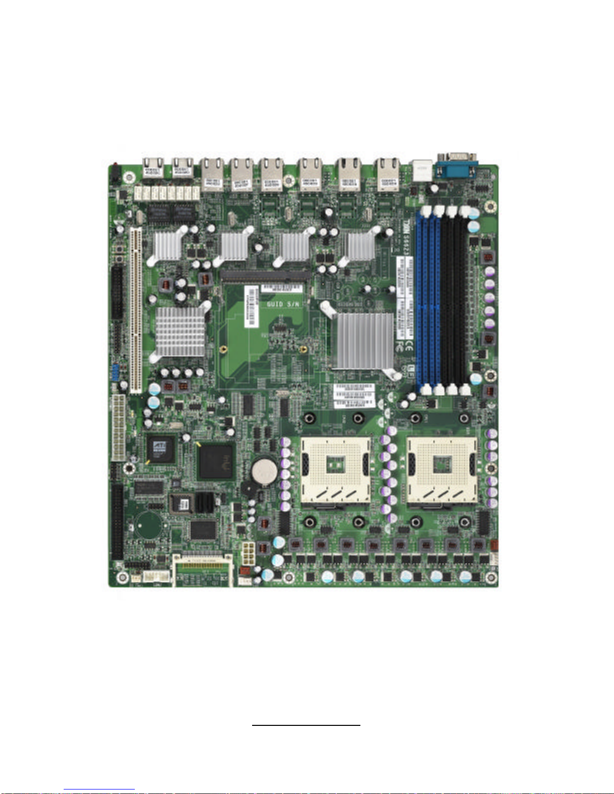
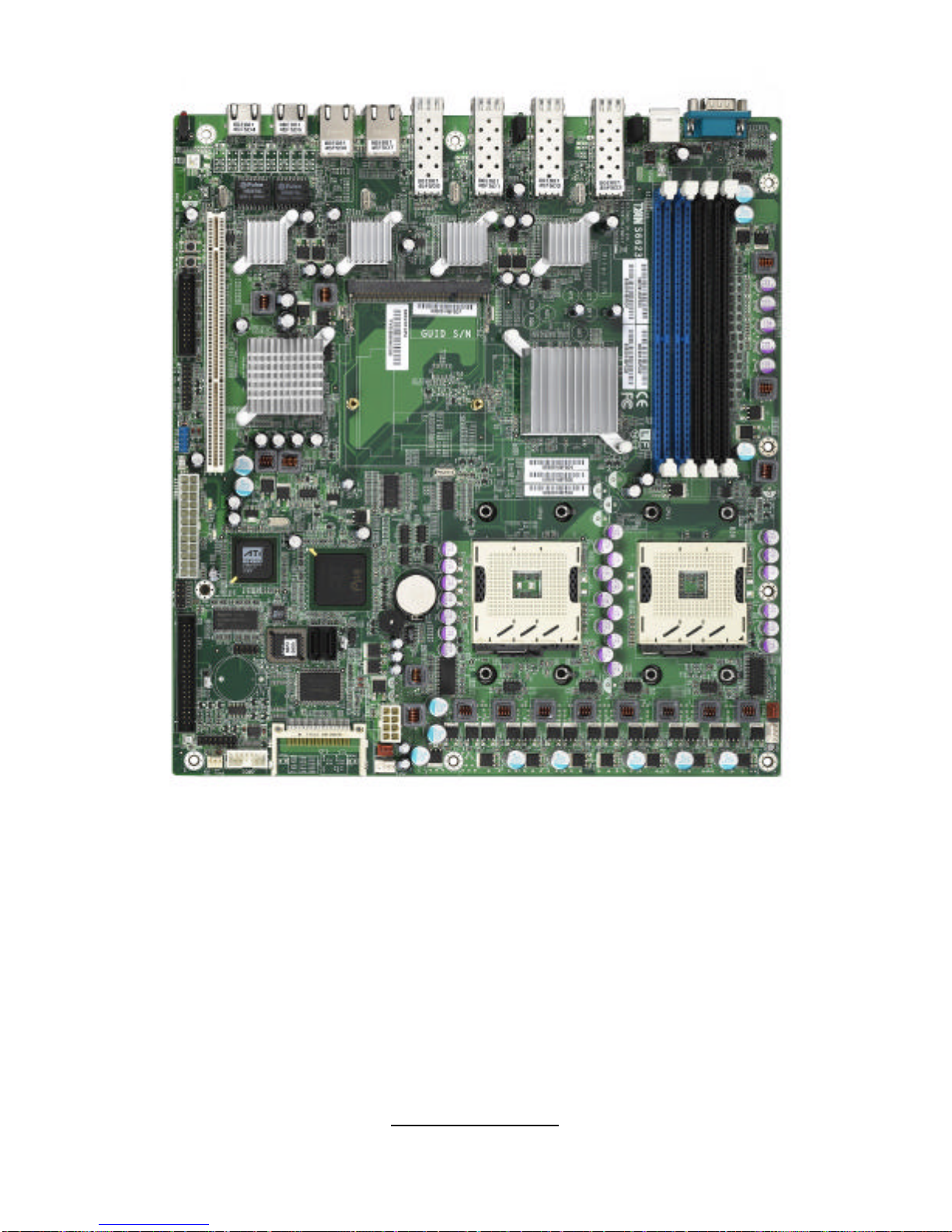
Congratulations on your purchase of the powerful Dual Intel processor solution,
the Triumph i7520 S6623. Based on Intel E7520 chipset, the S6623 offers
exceptional performance. Compatible with EPS12V power supplies, the EEB
3.51 form factor S6623 features an onboard ATI ES1000 PCI graphics
controller with 16 MB memory, four Intel 82571EB dual port Gigabit controllers
and 2 SATA ports from ICH5R, which provides a versatile solution for your
server needs.
Remember to visit TYAN’s Website at http://www.tyan.com. There you can find
information on all of TYAN’s products with FAQ’s, online manuals and BIOS
upgrades.
1.2 -Hardware Specifications
Processors
•Two 604-pin sockets support Intel
CPUs of the same type below:
?Xeon Dual Core (Paxville CPU) with
2x2MB L2
?Xeon (Nadona, 1M L2), up to
3.6GHz
?Xeon (Irwindale, 2M L2), up to
3.6GHz
?Xeon LV (Low Voltage) CPU, up to
2.8GHz
•Separated 4-phase VRD for each
CPU
Memory
•Four 240-pin DDR2 sockets support
up to 8GB
•Dual channel memory bus (must be
populated in pairs)
•Registered DDR2 400 compliant ECC
DIMM
•Supports 256MB, 512MB, 1GB and
2GB DIMM
Chipset
•Intel E7520 Memory Controller Hub
LAN Bypass
•Supports Bypass feature over one
pair of LAN ports (LAN 1 & 2)
Front Panel I/O Ports
•One serial port with D-Sub
connector
•Two USB ports with Dual-Stack
USB connector
•8 RJ45 Connectors (S6623P8B)
•Four of eight LAN ports could be
configured to Optical SFP
connectors (refer to Available
Models)
System Management
•Total 5 fan headers with control
and tachometer monitoring
•Monitors voltage for CPU,
Memory & Power Supply
•Monitors temperature for CPU &
environment
•Onboard LED: LAN bypass, Fault
FED Pin Header: Power LED &
HDD LED
•One pin header for Chassis

http://www.tyan.com
6
•Intel 82801ER I/O Controller Hub
(ICH5R)
•Intel 6700PXH PCI/PCI-X Controller
Hub
Integrated LAN Controllers
•Four Intel 82571EB dual port Gagabit
Controllers
•Configurable with total 8 Gigabit LAN
ports, Max. 4 of 8 ports could be over
Fiber connectors (refer to Available
Models)
Integrated 2D/3D Graphics
•Onboard ATI ES1000 PCI graphics
controller with 16MB memory
Expansion Slots
•One 64-bit 133MHz PCI-X slot
(3.3V) (M2052-RS)
•One Taro slot supports Tyan M6120
CN-1120 card
Integrated SATA Controller
•2 SATA ports from ICH5R
•RAID 0, 1 supported
Form Factor
•EEB 3.51 form factor (12”x 13”, 305
x 330mm)
Power Supply
•EPS 12V Power Supply (24-pin, 8-pin
power connectors)
Intrusion detection
•Supports Serial Console Redirect
•Optional SRAM to restore
customized private keys
•Supports Watch Dog Timer
BIOS
•AWARD BIOS®on 4Mbit Flash
ROM
•Supports ACPI 2.0
•Supports boot from USB device
•Power-on mode control for AC
power loss recovery
M6120 Networking Security add-
on card (optional)
•Cavium CN-1120-X Security
Macro Processor add-on card
supports IPsec/SSL
Integrated I/O
•One 40-pin IDE connector
•One 50-pin Compact Flash Type
II connector
•Two SATA connectors
•One pin header for USB ports
(supports two USB 2.0 devices)
•One shrouded header for serial
port
•One shrouded header for parallel
port
•One pin header for PS/2 mouse
and keyboard
•One pin header for VGA port
•One pin header for SMBUS
connection
Available Models
Model GbE over Fiber
GbE over Copper
LAN Bypass
Remarks
S6623T4P4
4 ports 4 ports N/A Standard
S6623P8B N/A 8 ports Yes standard
S6623T2P6
2 ports 6 ports N/A
S6623T4P2
4 ports 2 ports N/A

http://www.tyan.com
7
Chapter 2: Board Installation
Precautions: The Triumph i7520 supports SSI, EPS12V type power supplies
(24pin + 8pin) and will not operate with any other types. For proper power
supply installation procedures see page 37.
DO NOT USE ATX 2.x or ATXGES power supplies as they will damage the
board and void your warranty.
How to install our products right…the first time
The first thing you should do is reading this user’s manual. It contains important
information that will make configuration and setup much easier. Here are some
precautions you should take when installing your motherboard:
(1) Ground yourself properly before removing your motherboard from the
antistatic bag. Unplug the power from your computer power supply and
then touch a safely grounded object to release static charge (i.e. power
supply case). For the safest conditions, TYAN recommends wearing a
static safety wrist strap.
(2) Hold the motherboard by its edges and do not touch the bottom of the
board, or flex the board in any way.
(3) Avoid touching the motherboard components, IC chips, connectors,
memory modules, and leads.
(4) Place the motherboard on a grounded antistatic surface or on the
antistatic bag that the board was shipped in.
(5) Inspect the board for damage.
The following pages include details on how to install your motherboard into your
chassis, as well as installing the processor, memory, disk drives and cables.
NOTE
DO NOT APPLY POWER TO THE BOARD IF IT HAS BEEN
DAMAGED.

http://www.tyan.com
8
2.1-Board Image
This picture is representative of the latest board revision available at
the time of publishing. The board you receive may or may not look
exactly like the above picture.
Triumph i7520 (S6623P8B)

http://www.tyan.com
9
Triumph i7520 (S6623T4P4)

http://www.tyan.com
10
2.2 -Block Diagram
Triumph i7520 (S6623P8B) block diagram

http://www.tyan.com
11
Triumph i7520 (S6623T4P4) block diagram

http://www.tyan.com
12
2.3 -Board Parts, Jumpers and Connectors
Triumph i7520 (S6623P8B)

http://www.tyan.com
13
Triumph i7520 (S6623T4P4)
This diagram is representative of the latest board revision available at the time of
publishing. The board you receive may not look exactly like the above diagram.
Jumper Legend
©© OPEN -Jumper OFF, without jumper cover
©© CLOSED –Jumper ON, with jumper cover

http://www.tyan.com
14
Jumper/Connector
Function
FAN1/2/3/4/5 Fan Connector
VGA1 Pin Header for VGA Port
COM2 Box Header for COM Port
LPT1 Box Header for LPT Port
LPC1 Pin Header for LPC Ports
CF1 Compact Flash Connector
J8 200-pin SO-DIMM Socket
KM1 Pin Header for Keyboard & Mouse
SW1 System RESET Switch
SW2 System Power-ON Switch
FP-USB1 Pin Header for Internal USB Ports
FPIO1 Front Panel Connector
IDE1 IDE Connector
Red LED: shows fan/voltage/temperature fault
status
LED14 Green LED: shows LAN1/LAN2 LAN Bypass status
(for S6623P8B only)
SATA1/SATA2 Serial ATA Connector
JP2 Pin Header for Disk on Module Power Pin
CCMOS1 Clear CMOS Jumper

http://www.tyan.com
15
COM2
LPT1
FP
-
USB1

http://www.tyan.com
16
FP-USB1: Pin Header for Internal USB Ports
10 2
9 1
Signal Pin
Pin
Signal
VCC12VCC
-Data 0
34-Data 1
+ Data 0
56+ Data 1
GND 78GND
KEY 910
NC
COM2: Box Header for COM Port
10
2
9
1
Use these pin definitions to connect a port to COM2.
Signal
Pin
Pin
Signal
DCD 12DSR
RXD 34RTS
TXD 56CTS
DTR 78RI
GND 910
KEY
LPT1: Box Header for LPT Port
125
26
2
Signal
Pin
Pin
Signal
STB#
12AFD#
PD0 34ERR#
PD1 56INIT#
PD2 78SLIN#
PD3 910
GND
PD4 11
12
GND
PD5 13
14
GND
PD6 15
16
GND
PD7 17
18
GND
ACK#
19
20
GND
BUSY
21
22
GND
PE 23
24
GND
SLCT
25

http://www.tyan.com
17
SW2
FPIO1
FAN1
FAN2
FAN5
FAN4
FAN3

http://www.tyan.com
18
FAN1/FAN2/FAN3/FAN4/FAN5: Fan Connector with Speed Control
+12V
GND
TACH
1
+12V
NC
GND
TACH
1
Use these headers to connect the cooling fans to
the motherboard to monitor their fan speeds to
keep the system stable and reliable.
FPIO1: Front Panel Header
The motherboard provides one front panel header for electrical connection to
the front panel switches and LED’s.
Power_LED+
Power_LED-
PWR_ON+
GND
Warning LED+
Warning LED-
_
GND
INTRU-
24 6 8 10 12
14
16
18
1
3
5
7
9
11
13
15
17
HDD_LED+
HDD_LED-
GND
RST_SW+
VCC
Ext. Interrupt
5VSB
SMBUS Data
SMBUS Clock
SW2: System POWER-ON Switch
Pin 1 Pin 2 Pin 3 Pin 4
PWRSW-
PWRSW-
GND GND

http://www.tyan.com
19
J8
SW1
VGA1
KM1

http://www.tyan.com
20
VGA1: Pin Header for VGA Port
15
1
16
2
Signal Pin
Pin
Signal
Red 12Green
Blue 34NC
GND 56GND
GND 78GND
VCC 910
GND
NC 11
12
DDC Data
H. SYNC 13
14
v. SYNC
DDC Clock
15
16
KEY
KM1: Pin Header for Keyboard and Mouse
10 2
9 1
Signal Pin
Pin
Signal
VCC 12VCC
KEY 34KEY
KB Data
56Mouse Data
GND 78GND
KB CLK
910
Mouse CLK
J8: SO-DIMM Socket
Supports TYAN M6120 CN-1120 card.
SW1: System RESET Switch
Pin 1 Pin 2 Pin 3 Pin 4
RSTSW-RSTSW-GND GND
This manual suits for next models
2
Table of contents
Other TYAN Motherboard manuals

TYAN
TYAN THUNDER K8HR User manual

TYAN
TYAN TEMPEST I5000VF User manual

TYAN
TYAN M4881 User manual

TYAN
TYAN Toledo i3100 S5207 User manual

TYAN
TYAN Tsunami S1846S User manual

TYAN
TYAN S8020 User manual

TYAN
TYAN S5535 User manual

TYAN
TYAN TRINITY I845 User manual

TYAN
TYAN Triumph i7230 User manual

TYAN
TYAN S5517 User manual