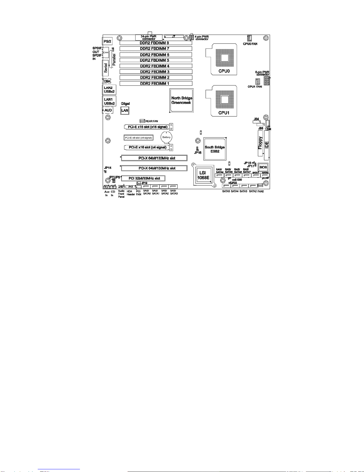
TYAN TEMPEST I5000XT User manual

1
Tempest i5000XT /// S2696
Version 1.20
Copyright
Copyright © TYAN Computer Corporation, 2006. All rights reserved. No part of
this manual may be reproduced or translated without prior written consent from
TYAN Computer Corp.
Trademark
All registered and unregistered trademarks and company names contained in
this manual are property of their respective owners including, but not limited to
the following.
TYAN, Tempest i5000XT are trademarks of TYAN Computer Corporation.
Intel, Greencreek, and combinations thereof are trademarks of Intel Corporation.
Phoenix, Phoenix-Award BIOS are trademarks of Phoenix Technologies.
Notice
Information contained in this document is furnished by TYAN Computer
Corporation and has been reviewed for accuracy and reliability prior to printing.
TYAN assumes no liability whatsoever, and disclaims any express or implied
warranty, relating to sale and/or use of TYAN products including liability or
warranties relating to fitness for a particular purpose or merchantability. TYAN
retains the right to make changes to product descriptions and/or specifications
at any time, without notice. In no event will TYAN be held liable for any direct or
indirect, incidental or consequential damage, loss of use, loss of data or other
malady resulting from errors or inaccuracies of information contained in this
document.

2
Table of Contents
Check the box contents! 3
Chapter 1: Introduction
1.1 Congratulations…………………………………………………………… 5
1.2 Hardware Specifications………………………………………………… 5
Chapter 2: Board Installation
2.1 Board Image……………………………………………………………… 8
2.2 Block Diagram……………………………………………………………. 9
2.3 Board Parts, Jumpers and Connectors………………………………... 10
2.4 Tips on Installing Motherboard in Chassis…………………………….. 19
2.5 Installing the Processor(s)………………………………....................... 20
2.6 Installing the Memory……………………………………………………. 23
2.7 Attaching Drive Cables………………………………………………….. 25
2.8 Installing Add-in Cards………………………………............................ 27
2.9 Connecting External Devices…………………………………………… 28
2.10 Installing the Power Supply……………………………………………... 29
2.11 Finishing up………………………………………………………………. 29
Chapter 3: BIOS Setup
3.1 About the BIOS…………………………………………………………… 30
3.2 BIOS Main Menu…………………………………………………………. 32
3.3 Advanced Menu………………………………………………………….. 38
3.4 Security Menu…………………………………………………………….. 55
3.5 Power Menu………………………………………………………………. 57
3.5 Boot Menu………………………………………………………………… 58
3.6 Exit Menu…………………………………………………………………. 60
Chapter 4: Diagnostics
4.1 Beep Codes………………………………………………………………. 61
4.2 Flash Utility……………………………………………………………….. 61
4.3 BIOS Post Code………………………………………………………….. 62
Appendix I: SMDC Information
Appendix II: How to Make a Driver Diskette
Glossary

3
Check the box contents!
1x Tempest i5000XT motherboard
1x 34-Pin floppy drive cable
1 x Ultra-DMA-100/66/33 IDE cable
3 x Serial ATA power cable
6 x Serial ATA Cable
1x Cable set: 9-pin Serial and 25-pin Parallel
1 x USB2.0 cable
2 x SAS cable
1 x Tempest i5000XT user’s manual
1 x Tempest i5000XT Quick Reference guide
1 x TYAN driver CD
1 x I/O shield
2 x CPU Mounting Kit
If any of these items are missing, please contact your vendor/dealer for
replacement before continuing with the installation process.

4

5
Chapter 1: Introduction
1.1 - Congratulations
You have purchased one of the most powerful workstation solutions. The
S2696 is a flexible Intel®platform for multiple applications, based on the Intel®
5000X (Greencreek) MCH and ESB2 chipsets.
Designed with the Dual LGA771 sockets, the S2696 supports Intel®Xeon®
Multi-core processors and 16/32GB DDR2-533/667 FB-DIMM memory. The
S2696 is also featured with an integrated Dual Gigabit Ethernet LAN, six SATA
ports and eight SAS ports based on the integrated LSI SAS controller. It's
ideally design to provide a versatile workstation platform.
Remember to visit TYAN’s Website at http://www.TYAN.com. There you can
find information on all of TYAN’s products with FAQs, online manuals and BIOS
upgrades.
1.2 - Hardware Specifications
Processor
•Dual LGA771 sockets
•Supports up to (2) Intel® Xeon®Multi-core
processors
•VRD 11.0
Chipset
•Intel®5000X (Greencreek) MCH and
ESB2 chipset
•Supports 1333/1066/667 MHz FSB
•Winbond W83627EHG Super I/O Chip
Memory
•Eight (8) 240-pin DDR2 FB-DIMM*
sockets
•4 memory channels
•Supports ECC DIMMs
•Maximum of 16/32GB DDR2-533/667
*FB-DIMM: Fully Buffered DIMM
Integrated SATA-II RAID
•Six (6) SATA-II ports
•3.0 Gb/s per port
•RAID 0, 1, 5, 10 support
Integrated LAN Controllers
•Intel Gigabit from ESB2 (w/ dual ports
“Gilgal’) – ASF2.0
•Two RJ-45 ports with LEDs
Integrated FireWire (1394a)
Controller
•TI TSB43AB22 1394a controller
•1394a channel for rear (connector)
•1394a channel for front (header)
Integrated Audio Controller
•HDA link
•Realtek ALC888 controller (High
Definition Audio)
•Line-in, Line-out, Mic-in rear ports
•Front panel audio header
•CD-in, Aux headers(4-pin configuration)
•SPDIF in/out in rear

6
Expansion Slots
•Two (2) PCI Express x16 slots (one with
x4 signal from ESB2)
•One (1) PCI Express x8 slot (x4 signal
from ESB2)
•Two (2) PCI-X 133/100MHz slots from
ESB2
•One (1) PCI 32-bit 33MHz slot
•Total six expansion slots
Integrated I/O
•One (1) 9-pin 16550 UART serial port
•Eight USB 2.0 ports (four at rear I/O,
four for two pin headers)
•PS/2 mouse and keyboard connectors
•Six (6) standard/integrated SATA
connectors
•Two (2) RJ-45 10/100/1000 LAN ports
•One (1) IDE and one (1) floppy
connectors
•Eight (8) SAS ports
System Management
•ADI ADT7470 Hardware Monitor
•CPU thermal & voltage monitor support
•Five (5) fan headers (4-pin configuration)
Integrated SAS (Optional)
•LSI 1068E SAS controller
•Operates at PCI-E x4 bus from ESB2
•Eight (8) SAS ports
•Supports 1.5 and 3.0 Gb/s SAS and
SATA data transfer rates.
•Raid support: IM/IME/IS
BIOS
•Phoenix®BIOS on 8Mbit Flash ROM
•Supports ACPI 2.0
•PXE via Ethernet, USB device boot
•PnP, DMI 2.0, WfM 2.0 power
management
•User-configurable H/W monitoring
•Auto-configuration of hard disk types
•Multiple boot options
•48-bit LBA support
Trusted Platform Management
(TPM)
•Infineon SLB9635TT 1.2 (with 5000X-G
chipset)
Form Factor
•SSI/Extended ATX (12” x 13”)
•EPS12V/SSI (24+8+4 pin) power
connectors
•Stacked PS/2 keyboard and mouse
connectors
•Stacked Serial (1) and parallel (1)
connectors
•Two stacked USB 2.0 (two) and RJ-45
(1) connectors
•FireWire (1394a) connector
•Stacked Line-in, Line-out, Mic-in audio
connectors
Regulatory
•FCC Class B (DoC)/BSMI
•European Community CE (DoC)
Software Specifications
OS (Operating System) Support
Microsoft Windows 2000 Pro
Microsoft Windows XP Pro (32-bit)
Microsoft Windows XP Pro (64-bit)
TYAN reserves the right to add support or discontinue support for any OS with or
without notice.

7
Chapter 2: Board Installation
You are now ready to install your motherboard. The mounting hole pattern of
the S2696 matches the Extended ATX specification. Before continuing with
installation, confirm that your chassis supports an Extended ATX motherboard.
How to install our products right… the first time
The first thing you should do is reading this user’s manual. It contains important
information that will make configuration and setup much easier. Here are some
precautions you should take when installing your motherboard:
(1) Ground yourself properly before removing your motherboard from the
antistatic bag. Unplug the power from your computer power supply and
then touch a safely grounded object to release static charge (i.e. power
supply case). For the safest conditions, TYAN recommends wearing a
static safety wrist strap.
(2) Hold the motherboard by its edges and do not touch the bottom of the
board, or flex the board in any way.
(3) Avoid touching the motherboard components, IC chips, connectors,
memory modules, and leads.
(4) Place the motherboard on a grounded antistatic surface or on the
antistatic bag that the board was shipped in.
(5) Inspect the board for damage.
The following pages include details on how to install your motherboard into your
chassis, as well as installing the processor, memory, disk drives and cables.
NOTE DO NOT APPLY POWER TO THE BOARD IF IT HAS BEEN
DAMAGED

8
2.1- Board Image
This picture is representative of the latest board revision available at
the time of publishing. The board you receive may or may not look
exactly like the above picture.

9
2.2 - Block Diagram
S2696 Block Diagram

10
2.3 - Board Parts, Jumpers and Connectors
This diagram is representative of the latest board revision available at the time of
publishing. The board you receive may not look exactly like the above diagram.

11
Jumper Legend
OPEN - Jumper OFF, without jumper cover
CLOSED – Jumper ON, with jumper cover
Jumper/Connector Function
JP1 Internal Buzzer Jumper
J15 Audio Front Panel
JP7/JP8 LAN Enable/Disable Jumper
E50 CMOS Clear Jumper
JP10 PS/2 Devices Wake up Enable Jumper
JP14 FW Write Protect Jumper
JP16 PCI-X Frequency Setting Jumper
JP19 Chassis Intrusion Jumper
JP23 BIOS Recovery Jumper
J84/J85 USB 2.0 Connector
J7 Front Panel Header
P17 HDA Digital Header
SATA-II 0/1/2/3/4/5 SATA-II Connectors
SAS 0/1/2/3/4/5/6/7 SAS Connectors
CPU0 FAN / CPU1 FAN CPU0/1 Fan Connectors

12
JP1: Internal Buzzer Enable/Disable Jumper
1
Use this jumper to disable the onboard internal
Buzzer.
1
(Default)
Use this jumper to enable the onboard internal
Buzzer.

13
E50: CMOS Clear Jumper
13
Normal
(Default)
31
Clear
Use this jumper when you have forgotten your
system/setup password or need to clear the system
BIOS settings.
How to clear the CMOS data
-Power off system and disconnect the power
supply from the AC source
-Use jumper cap to close pin_2 and 3 for several
seconds to clear the CMOS
-Replace the jumper cap to close pin_1 and 2
Reconnect the power supply to the AC source
and power on the system
J15: Audio Front Panel
AUD_MIC_L 1 2 GND
AUD_MIC_R 3 4 PRESENCE
AUD_HP_R 5 6 MIC_sence_return
Sense_send 7 8 KEY
AUD_HP_L 9 10 HP_sense_return
JP7/JP8: LAN Enable/Disable Jumper
11
3
(Default)
JP7: Enable the 1st LAN port
JP8: Enable the 2nd LAN port
3
1
JP7: Disable the 1st LAN port
JP8: Disable the 2nd LAN port

14
JP14: FWH Write Protect Jumper
1
(Default)
Use this jumper to disable the FWH write protect.
1
Use this jumper to enable the FWH write protect.

15
JP10: PS/2 Devices Wake up Jumper
JP19: Chassis Intrusion Jumper
13
(Default)
Use this jumper to disable the system chassis
intrusion alarm.
3
1
Use this jumper to trigger the system chassis
intrusion alarm.
J84/J85: Front Panel USB2.0 Connectors
Use these two headers to connect the USB devices
via the enclosed USB cable.
11
3
Use this jumper to disable the PS/2 devices from
waking up.
3
1
(Default)
Use this jumper to enable the waking up of the
PS/2 devices.
Key 1 2 Reserved
Power 3 4 Power
USB_A- 5 6 USB_B-
USB_A+ 7 8 USB_B+
GND 9 10 GND
Key 11 12 NC

16
JP23: BIOS Recovery Jumper
1
(Default) No BIOS recovery function
1
BIOS will be forced into recovery. BIOS image
will be loaded from floppy.

17
JP16: PCI-X Frequency Setting Jumper
1
3
(Default)
Use this jumper to set the PCI-X frequency at
133MHz.
1
3
Use this jumper to set the PCI-X frequency at
100MHz.
3
1
Use this jumper to set the PCI-X frequency at
66MHz.
P17: Intel HD Audio Digital Header
Intel HD Audio Digital Header is used to support one HD Codec on a cabled
up card.
SATA-II 0/1/2/3/4/5: SATA-II Connector
7 GND
6 RXP
5 RXN
4 GND
3 TXN
2 TXP
7
1
1 GND
Connects to the SATA-II ready drives via the
SATA-II cable
You may use these six SATA-II ports for
RAID 0, 1, 5 and 10 through the embedded
Intel ESB2 chipset.
BCLK 1 2 GND
RST# 3 4 DVDD_IO
SYNC 5 6 GND
SDO 7 8 3.3V_DVDD_CORE
SDI 9 10 +12V
Reserved 11 12 KEY
Reserved 13 14 3.3V_DUAL
Reserved 15 16 GND

18
SAS 0/1/2/3/4/5/6/7: SAS Connector
7 GND
6 RXP
5 RXN
4 GND
3 TXN
2 TXP
7
1
1 GND
Connects to the SAS ready drives via the SAS
cable or SATA ready drives via the SATA cable
You may use these eight SAS ports to have
the support of RAID IM, IME and IS through
the embedded LSI1068E chip.
CPU0 FAN/CPU1 FAN: CPU0/1 Fan Connectors
12V
PWM
GN
D
Ta c ho met e r
Use these two headers to connect the CPU
cooling fans to your motherboard to keep the
system at optimum performance levels.
J7: Front Panel Header
The Front Panel Header is used to connect some control or signal wires from
motherboard to chassis, such as HDD LED, power LED, power button, and
reset button.
GND 1 2 SPKR_OUT_L
SLP_LED + 3 4 KEY
KEY 5 6 GND
PWR_LED +_0 7 8 SPKR_OUT_H
PWR_LED +_1 9 10 NC
GND 11 12 NC
3.3V 13 14 KEY
MSG_LED 15 16 NC
KEY 17 18 SCSI_LED -_0
3.3V 19 20 SCSI_LED -_1
HDD_LED - 21 22 NC
GND 23 24 KEY
PWRBTN_N 25 26 GND
SLPBTN_N 27 28 GND
RESET_N 29 30 GND

19
2.4 - Tips on Installing Motherboard in Chassis
Before installing your motherboard, make sure your chassis has the
necessary motherboard support studs installed. These studs are usually
metal and are gold in color. Usually, the chassis manufacturer will pre-install
the support studs. If you are unsure of stud placement, simply lay the
motherboard inside the chassis and align the screw holes of the motherboard
to the studs inside the case. If there are any studs missing, you will know
right away since the motherboard will not be able to be securely installed.
Some chassis’ include plastic studs instead of metal. Although the plastic
studs are usable, TYAN recommends using metal studs with screws that will
fasten the motherboard more securely in place.
Below is a chart detailing what the most common motherboard studs look like
and how they should be installed.

20
2.5 - Installing the Processor(s)
Your S2696 supports the latest processor technologies from Intel. Check the
TYAN website for latest processor support:
http://www.tyan.com
Processor Installation
The processor should be installed carefully. Make sure you are wearing an
antistatic strap and handle the processor as little as possible.
Follow these instructions to install your processor
1. Locate the processor socket on the motherboard and lift the protective
cover off as shown.
WARNING:
This new processor socket designed
by Intel is easily damaged. The
processor has to be installed very
carefully to prevent the contact pins
in the socket from breaking. It is
strongly recommended that the
processor installation process
should be handled by an
experienced technician.
2. Pull the locking lever out of it’s locked position and let it spring into the
open position.
This manual suits for next models
1
Table of contents
Other TYAN Motherboard manuals

TYAN
TYAN TAHOE AT User manual

TYAN
TYAN TOMCAT N3400B User manual

TYAN
TYAN THUNDER K8SRE User manual

TYAN
TYAN S5515 User manual

TYAN
TYAN THUNDER K7 User manual

TYAN
TYAN THUNDER 2500 User manual

TYAN
TYAN Tomcat i845GV S2198 User manual

TYAN
TYAN S2054 User manual

TYAN
TYAN THUNDER K8SD PRO User manual

TYAN
TYAN S7086 User manual

TYAN
TYAN TEMPEST I5000VF User manual

TYAN
TYAN TRINITY KT-A User manual

TYAN
TYAN THUNDER LE-T User manual

TYAN
TYAN TITAN TURBO AT User manual

TYAN
TYAN TOMCAT H1000S User manual

TYAN
TYAN THUNDER TOMCAT H1000E User manual

TYAN
TYAN Tiger K8WE S2877 User manual

TYAN
TYAN Thunder i7501 S2720-533 User manual

TYAN
TYAN THUNDERBOLT User manual

TYAN
TYAN S7076 User manual