manuals.online logo
Brands
  1. Home
  2. •
  3. Brands
  4. •
  5. Tyco Electronics
  6. •
  7. Industrial Electrical
  8. •
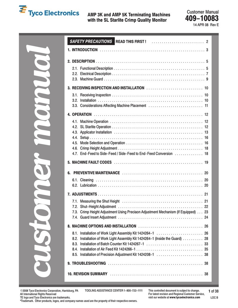
  9. Tyco Electronics BDA User manual

Tyco Electronics BDA User manual

ENERGY PRODUCTS
2005-06-Arrester installation instr-CIS-Rev 1
Installation Instruction
Polymeric Medium Voltage
ZnO Surge Arresters
Type:
BDA, CPA, HDA, NDA, OCP, SPA
ISO 9001 & 14001
EC 60099-4; Ammedment 2 2001
Medium Voltage ZnO Surge Arresters
2005-06-Arrester installation instr-CIS-Rev 1
1
Safety Warning
Surge arresters should be installed only
by competent personnel familiar with
good safety practices and the handling of
high voltage electrical equipment.
The enclosed installation instruction is not
intended as a substitute for adequate training and
experience in safe procedures nor to replace or
supersede existing safety, operating and
maintenance procedures.
Installation Note
Arresters are typically to be installed between the line
conductor and ground.
Only in a few special cases (motor protection, cable
sheath protection, ...) arresters may be installed in a
different way. Please consult your system administrator
for details if required.
Before Starting

Check if all parts (surge arrester & accessories)
are included in the box according to the
description printed on the carton label.

If the accessories come disassembled please
assemble all parts as appropriate prior to the
final installation. Please refer to the enclosed
drawings for the correct torque.

Check if the arrester or the accessories have
been damaged during transport. Never install a
damaged arrester. It may fail violently, causing
severe personal injury.

All surge arresters carry a nameplate giving
details of arrester type and voltage rating. Check
the voltage rating of each single arrester. Do not
install arresters with voltage ratings other than
specified by your system administrator.

Check if the arrester and the accessories fulfill
the local requirements in terms of mechanical
dimensions. Do not alter the arrangement of the
accessories or the accessory itself!
Do not leave out any parts!

Please ask your local system administrator about
the minimum clearances you have to meet
between live parts and ground. The values for
outdoor substations do apply. If not available you
may refer to Table 1 instead showing the values
according to IEC 60071-2.

If you are installing a special kind of surge
arresters like SPA-I with insulated line lead,
shorter clearances may apply. Please refer to the
relevant addendum covering those arresters.

If unsure about assembly sequence, please
request and refer to relevant assembly drawing.
Arresters applied at voltages higher than
rating may cause damage and injury.
Check the arrester rating, marked clearly
on the name plate, to ensure correct
application!
Installation
Do not handle the polymeric housing of the
arrester with tools!
Certain type of arresters ave a protrusion at both
ends of the arrester.
You can hold the arrester there safetly with a
second wrench to fasten the nuts included with
some accessories. Use the protrusion on the side
close to the nut to be fastened.
In case the arrester hasn’t got a protrusion please
support the arrester by hand.

Make sure that the electrical system is de-
energized and earthed.
!
!
Medium Voltage ZnO Surge Arresters
2005-06-Arrester installation instr-CIS-Rev 1
2

Strictly follow the local safety instructions and
maintenance procedures.

Select a mounting position as close as
practicable to the equipment (transformer, cable
termination, ...) to be protect in order to obtain
the highest degree of protection.

Connect the ground lead to the arrester ground
terminal stud or accessory. Fasten the nut to the
torque indicated in the relevant drawing.

In case the arrester comes with a metallic
bracket attached it is possible to connect the
ground lead to the bracket. The line lead may
also be left out if the bracket or the arrester
terminal is directly mounted on the earthed tank
or frame of the apparatus provided that the
electrical contact is reliable and earthing
interconnections are suitable. In doubt please
use separate conductor cables or strip to
connect the bracket or the arrester terminal to
system earth.

Connect the line lead to the arrester line terminal
stud or accessory. Fasten the nut to the torque
indicated in the relevant drawing.

Make the arrester ground and line connections
as short as possible avoiding sharp bends and
loops. If the line connection cannot be made
short, consider connecting the line directly to the
arrester and continue from there.

The continuous mechanical stress applied to the
arrester i.e. via the connection shall not exceed
the specified values. Mechanical overload may
shorten the arrester’s service lifetime
significantly.

In case the arrester is equipped with a
disconnector device (a „D“ is shown in the middle of
the description, e.g. ARR-ACC-BDM. ) make sure that
the ground lead is flexible enough to allow the
disconnector to operate properly.

Re-energize the electrical system. Avoid single-
phase switching because this may lead to ferro-
resonance of the transformer! If single-phase
switching needs to be done, make sure that you
are operating with protection as arresters may be
destroyed in case of ferro-resonances.
Maintenance
Bowthorpe arresters are maintenance free. There
are no serviceable parts inside.
Performance checks are not required during the
expected service life.
Removing Arresters
The polymeric housing of failed surge
arrester sometimes is inflated. This can happen if
the fault current is switched off fast before the
housing ruptures!
This typically does not represent a hazard if the arrester
is allowed to cool down to ambient temperature. Be
careful anyway when removing such kind of arresters.

Make sure that the electrical system is de-
energized.

Strictly follow the local safety instructions and
maintenance procedures.

Disconnect the line lead from the circuit.
þ
Disconnect the ground lead from the circuit.
Clearances
ab a
System Voltage Um
[kV]
ph/ph*(a)
[mm] ph/ground*(b)
[mm]
7,2 152 121
12 182 151
17,5 222 191
24 282 251
36 382 351
*
local regulations and standards may require
wider clearances!
Table 1: Minimum clearances following IEC60071-2
for altitudes up to 1000 m (3300 ft).
!
Medium Voltage ZnO Surge Arresters
2005-06-Arrester installation instr-CIS-Rev 1
3
max.
50 Nm !
Fig 1: Max. torque at the terminals of the arreste
Other considerations: Altitude
The clearances quoted above are
recommended min clearances required
for applications up to 3,300 ft (1,000m
metres). For installations at higher
altitudes, the accepted practice is to add
3% to the clearance length for every
1,000 ft (300 metres) increase in altitude
above 3,300 ft (1,000 metres). The 3%
is also added to the external housing
flashover distance of the arrester itself.
The information contained in this installation instruction is intended to describe the correct method of installation for this product. However, Tyco
Electronics has no control over the field conditions which influence product installation. It is user’s responsibility to determine the suitability of the
installation method in the user’s field conditions. Tyco Electronics only obligations are those in Tyco Electronics standard Conditions of Sale for this
product and in no case will Tyco Electronics be liable for any other incidental, indirect or consequential damages arising from the use or misuse of the
product.
Tyco Electronics Raychem GmbH
Energy Division
Finsinger Feld 1
85521 Ottobrunn/Munich
Germany
Tel: +49 89 6089 485
Fax: +49 89 6089-484
EN-CEE/CIS@tycoelectronics.com
Tyco Electronics Raychem Ltd
Energy Division
100-104 Shannon Industrial Estate,
Shannon,
Co. Clare
Ireland
Tel: +353 61 470839
Fax: +353 61 471169

This manual suits for next models

5

Other Tyco Electronics Industrial Electrical manuals

Tyco Electronics FIST-MB2-T User manual

Tyco Electronics

Tyco Electronics FIST-MB2-T User manual

Tyco Electronics AMP 3K Reference guide

Tyco Electronics

Tyco Electronics AMP 3K Reference guide

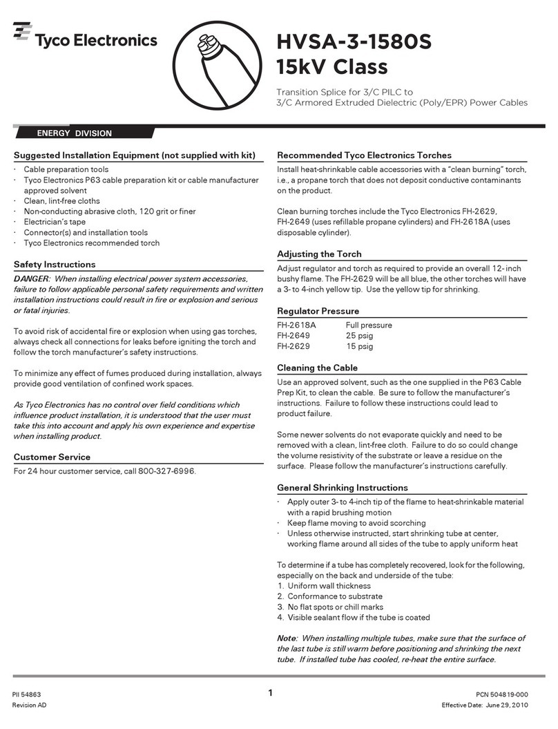
Tyco Electronics HVSA-3-1580S Series User manual

Tyco Electronics

Tyco Electronics HVSA-3-1580S Series User manual

Tyco Electronics Raychem FIST-MB2-S User manual

Tyco Electronics

Tyco Electronics Raychem FIST-MB2-S User manual

Popular Industrial Electrical manuals by other brands

Moeller NHI-E PKZ0 Series installation instructions

Moeller

Moeller NHI-E PKZ0 Series installation instructions

Murata GRM0335C2AR50BA01 Series Reference sheet

Murata

Murata GRM0335C2AR50BA01 Series Reference sheet

Murata ZRA21MR60J476ME11 Series Reference sheet

Murata

Murata ZRA21MR60J476ME11 Series Reference sheet

Murata GRM0225C1E7R8BA03 Series Reference sheet

Murata

Murata GRM0225C1E7R8BA03 Series Reference sheet

Murata LLA215R71A224MA14 Series Reference sheet

Murata

Murata LLA215R71A224MA14 Series Reference sheet

Siemens SIVACON 8PS BD2 Series installation instructions

Siemens

Siemens SIVACON 8PS BD2 Series installation instructions

Murata GRM0225C1E2R4BA03 Series Reference sheet

Murata

Murata GRM0225C1E2R4BA03 Series Reference sheet

Murata GRJ188R72A223KE11 Series Reference sheet

Murata

Murata GRJ188R72A223KE11 Series Reference sheet

Eaton W-SLC-7.2 INSTRUCTIONS FOR THE INSTALLATION, OPERATION AND MAINTENANCE

Eaton

Eaton W-SLC-7.2 INSTRUCTIONS FOR THE INSTALLATION, OPERATION AND MAINTENANCE

Bullhorn RM2000 Series Installation and configuration guide

Bullhorn

Bullhorn RM2000 Series Installation and configuration guide

Fluke Calibration P5531 operating instructions

Fluke Calibration

Fluke Calibration P5531 operating instructions

SOMFY Connect UAI Plus Integration guide

SOMFY

SOMFY Connect UAI Plus Integration guide

Siemens SIMOTION D45 Series manual

Siemens

Siemens SIMOTION D45 Series manual

ABB TMAX XT XT2 THERMOMAGNETIC Disassembly instructions

ABB

ABB TMAX XT XT2 THERMOMAGNETIC Disassembly instructions

Murata GRJ21BR72A104KE01 Series Reference sheet

Murata

Murata GRJ21BR72A104KE01 Series Reference sheet

Murata GRM155R71C224KA12 Series Reference sheet

Murata

Murata GRM155R71C224KA12 Series Reference sheet

Murata GRM1555C1H1R0CA01 Series Reference sheet

Murata

Murata GRM1555C1H1R0CA01 Series Reference sheet

Murata GJM0335C1E2R9WB01 Series Reference sheet

Murata

Murata GJM0335C1E2R9WB01 Series Reference sheet

manuals.online logo
manuals.online logoBrands
  • About & Mission
  • Contact us
  • Privacy Policy
  • Terms and Conditions

Copyright 2025 Manuals.Online. All Rights Reserved.