manuals.online logo
Brands
  1. Home
  2. •
  3. Brands
  4. •
  5. Tyco
  6. •
  7. Measuring Instrument
  8. •
  9. Tyco TIP User manual

Tyco TIP User manual

Model TIP Indicator Post Supervisory Switch
APACOnly
NATIONAL FIRE PROTECTION ASSOCIATION and NFPA are registered trademarks of National
Fire Protection Association
Important: Refer to technical data sheet TFP2300
for warnings pertaining to regulatory and health
information.
Scan the QR code or enter the URL in a web
browser to access the most up-to-date electronic
version of this document. Data rates may apply.
docs.jci.com/tycofire/indicator-post-supervisory-switch
NOTICE
The TYCO Model TIP Indicator Post Supervisory
Switch described herein must be installed and
maintained in compliance with this document, in
addition to the standards of any other authorities
having jurisdiction. Failure to do so may impair the
performance of the related devices.
The owner is responsible for maintaining their fire
protection system and devices in proper operating
condition. Contact the installing contractor or product
manufacturer with any questions.
General description
The TYCO Model TIP Indicator Post Supervisory Switch is
designed to monitor the position of a wall and yard post
indicator type fire sprinkler control valve, and indicate
when the valve is not in the open position.
The switch is weather proof and tamper resistant. The
cover incorporates tamper resistant screws that require
a special tamper resistant key for removal. One tamper
resistant key is supplied with each device.
The unit mounts to a ½ in. NPT threaded hole in the post
indicator housing.
Models
The switch models are based on the number of sets of
single-pole, double-throw (SPDT) contacts as shown in
Table 1.
Table 1: Switch models
Model Description
TIP-1 1 set of SPDT contacts
TIP-2 2 sets of SPDT contacts
TFP2112
MAY 2022
Assembly
Figure 1: Components and dimensions
Callout Description
1 Cover
2 Gasket
3 Housing
4 Tamper resistant cover screw
5 Trip rod locking screw
6 Trip rod
Callout Dimension
A 4.55 in. (116 mm)
B 2.36 in. (60 mm)
C 5.04 in. (128 mm)
D Minimum: 0.50 in. (13 mm); Maximum: 2.00
in. (51 mm)
E 1.65 in. (42 mm)
F 1/2 in. NPT
Technical Data
Approvals
• UL and cUL Listed
• FM Approved
• CE
Contact ratings
• 10 A at 125/250 VAC
• 2.5 A at 30 VDC Resistive
Operating temperature range
• -40°F to +140°F (-40°C to +60°C)
Dimensions
• See Assembly section
Physical characteristics
Cover Die-cast finish, powder coat
Base Die-cast finish
Note: All components have corrosion resistant
finishes.
Operation
The switch mounts on a ½ in. NPT threaded hole in the
post indicator housing. The switch is a spring loaded
device. In the normal condition (valve fully open) the trip
rod is pushing against the valve actuator. As the indicator
valve closes, the valve actuator moves away from the trip
rod of the switch. The internal spring moves the trip rod
over and trips the switch.
Model TIP Indicator Post Supervisory Switch APAC Only2
Installation
The TYCO Model TIP Indicator Post Supervisory Switch
must be installed according to the instructions in this
section.
Installation arrangements
Figure 2: Indicator target movement towards valve as
valve opens
Callout Component
6 Trip rod
Figure 3: Indicator target movement away from valve
as valve opens
Callout Component
6 Trip rod
Installing the switch
Before you begin:
• The switch must be installed according to the
instructions in this section.
• The switch may be installed according to the
installation arrangements shown in the Installation
arrangements section.
To install the switch, complete the following steps:
1. Ensure there is adequate clearance for installation
or removal of the switch.
2. Position the indicator valve to fully open.
3. Partially close the indicator valve and observe the
direction that the target assembly moves.
4. Re-open the valve, make sure that OPEN appears in
the window of the housing.
5. Remove the ½ in. plug from the valve.
6. Loosen the locking screw that holds the trip rod
in place and adjust the trip rod. When properly
adjusted, the rod should extend past the valve
screw, but no so far that it contacts the clamp bar.
Note: If the trip rod is too long, loosen the
locking screw and remove the trip rod from
the the trip lever. Use a pliers to break off the
1 in. (25.4 mm) long-notched section.
7. Tighten the locking screw to 5 in-lbs (0.56 Nm)
minimum to hold the trip rod in place and properly
seal the enclosure.
Wiring the switch
Before you begin:
• The switch must be wired according to the instructions
in this section.
To wire the switch, complete the following steps:
1. Remove the tamper resistant screw with a key.
Note: Do not leave the cover off for an
extended period of time.
2. Route the wiring through an agency approved
conduit connector and attach the connector to the
switch.
3. Connect the wiring to the appropriate terminals
according to the intended use as shown in Figure 4
and in compliance with all local electrical codes.
Figure 4: Typical wiring connections
Model TIP Indicator Post Supervisory Switch APAC Only 3
Care and maintenance
The TYCO Model TIP Indicator Post Supervisory Switch
must be maintained and serviced in accordance with
this section, in addition to any specific requirements of
the NFPA, and any impairment must be immediately
corrected. The inspection procedure must be performed
as described.
Before closing a fire protection system control valve for
inspection or maintenance work on the fire protection
system that it controls, permission to shut down the
affected fire protection system must first be obtained
from the proper authorities and all personnel who may
be affected by this action must be notified. After placing
a fire protection system in service, notify the proper
authorities and advise those responsible for monitoring
proprietary and/or central station alarms.
The owner is responsible for the inspection, testing,
and maintenance of their fire protection system and
devices in compliance with this document, as well as
with the applicable standards of the NATIONAL FIRE
PROTECTION ASSOCIATION such as NFPA 25, in addition
to the standards of any authority having jurisdiction (AHJ).
Contact the installing contractor or product manufacturer
with any questions.
It is recommended that automatic sprinkler systems
be inspected, tested, and maintained by a qualified
inspection service.
Inspecting the supervisory switch
Before you begin:
• The inspection procedure must be performed as
specified, in addition to any specific requirements of
the NFPA, and any impairment must be immediately
corrected.
• The operation of the supervisory switch and its
associated monitoring system must be tested upon
completion of installation.
• Test the switch periodically in accordance with
applicable NFPA codes and standards and/or the AHJ. A
quarterly arrangement is recommended.
To inspect the switch, complete the following steps:
1. Turn the valve operating mechanism towards the
the closed position. Verify the switch operates
within the first two revolutions.
2. Fully close the valve and verify the switch does not
reset.
3. Fully open the valve and verify the switch restores
to the normal condition.
Limited Warranty
For warranty terms and conditions, visit http://www.tyco-
fire.com.
Ordering Procedure
Contact your local distributor for availability. When
placing an order, indicate the full product name, and part
number (PN).
Indicator post supervisory switch
Specify: Model (see Table 2), Indicator post supervisory
switch, quantity, PN (see Table 2).
Table 2: Switch part numbers
Model Part number
TIP-1 300101
TIP-2 300103
© 2022 Johnson Controls. All rights reserved. All specifications and other information shown were current as of document revision and
are subject to change without notice.
www.johnsoncontrols.com

Other Tyco Measuring Instrument manuals

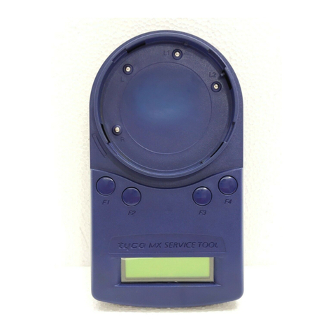
Tyco VIGILANT MX 850EMT User manual

Tyco

Tyco VIGILANT MX 850EMT User manual

Tyco F3200 User manual

Tyco

Tyco F3200 User manual

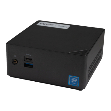
Tyco Exacq C-Series Standard User manual

Tyco

Tyco Exacq C-Series Standard User manual

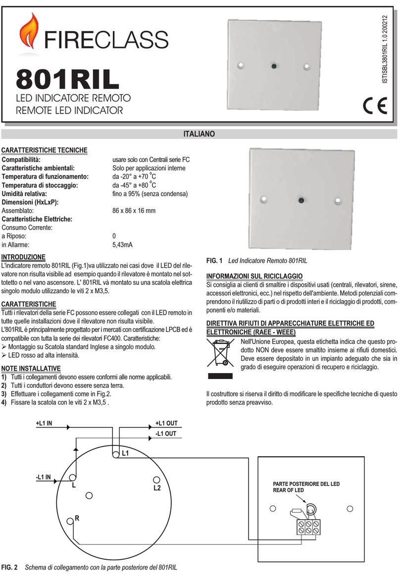
Tyco FireClass 801RIL User manual

Tyco

Tyco FireClass 801RIL User manual

Tyco 801AP MX User manual

Tyco

Tyco 801AP MX User manual

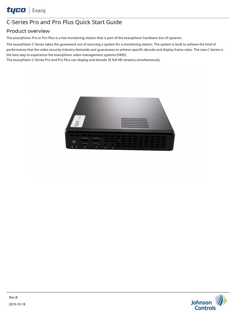
Tyco Exacq C-Series Pro User manual

Tyco

Tyco Exacq C-Series Pro User manual

Popular Measuring Instrument manuals by other brands

Owon Lilliput HDS1021M user manual

Owon

Owon Lilliput HDS1021M user manual

Parasport NeoXs user manual

Parasport

Parasport NeoXs user manual

GANN Hydromette RTU 600 operating manual

GANN

GANN Hydromette RTU 600 operating manual

Hach Hach SL1000 user manual

Hach

Hach Hach SL1000 user manual

PCE Health and Fitness PCE-RM 100 user manual

PCE Health and Fitness

PCE Health and Fitness PCE-RM 100 user manual

BEA LZR-MICROSCAN U920 user guide

BEA

BEA LZR-MICROSCAN U920 user guide

NI PXIe-4190 Getting started

NI

NI PXIe-4190 Getting started

DAKOTA ULTRASONICS MMX-6 Operation manual

DAKOTA ULTRASONICS

DAKOTA ULTRASONICS MMX-6 Operation manual

TDE Instruments 101398 instruction manual

TDE Instruments

TDE Instruments 101398 instruction manual

Thermo Interceptor user manual

Thermo

Thermo Interceptor user manual

ISCO 4230 Installation and operation guide

ISCO

ISCO 4230 Installation and operation guide

ADCMT 12706A Operation manual

ADCMT

ADCMT 12706A Operation manual

Turf-Tec Light-DLI-W quick start guide

Turf-Tec

Turf-Tec Light-DLI-W quick start guide

Safeside R-3D2 Series Installation and operating instructions

Safeside

Safeside R-3D2 Series Installation and operating instructions

SKF Inspector 400 manual

SKF

SKF Inspector 400 manual

Fluke 1587 FC Calibration manual

Fluke

Fluke 1587 FC Calibration manual

ThermoFisher Scientific 43iQHL instruction manual

ThermoFisher Scientific

ThermoFisher Scientific 43iQHL instruction manual

TESTO 338 instruction manual

TESTO

TESTO 338 instruction manual

manuals.online logo
manuals.online logoBrands
  • About & Mission
  • Contact us
  • Privacy Policy
  • Terms and Conditions

Copyright 2025 Manuals.Online. All Rights Reserved.