manuals.online logo
Brands
  1. Home
  2. •
  3. Brands
  4. •
  5. Solinst
  6. •
  7. Measuring Instrument
  8. •
  9. Solinst 101 P7 SC1000 User manual

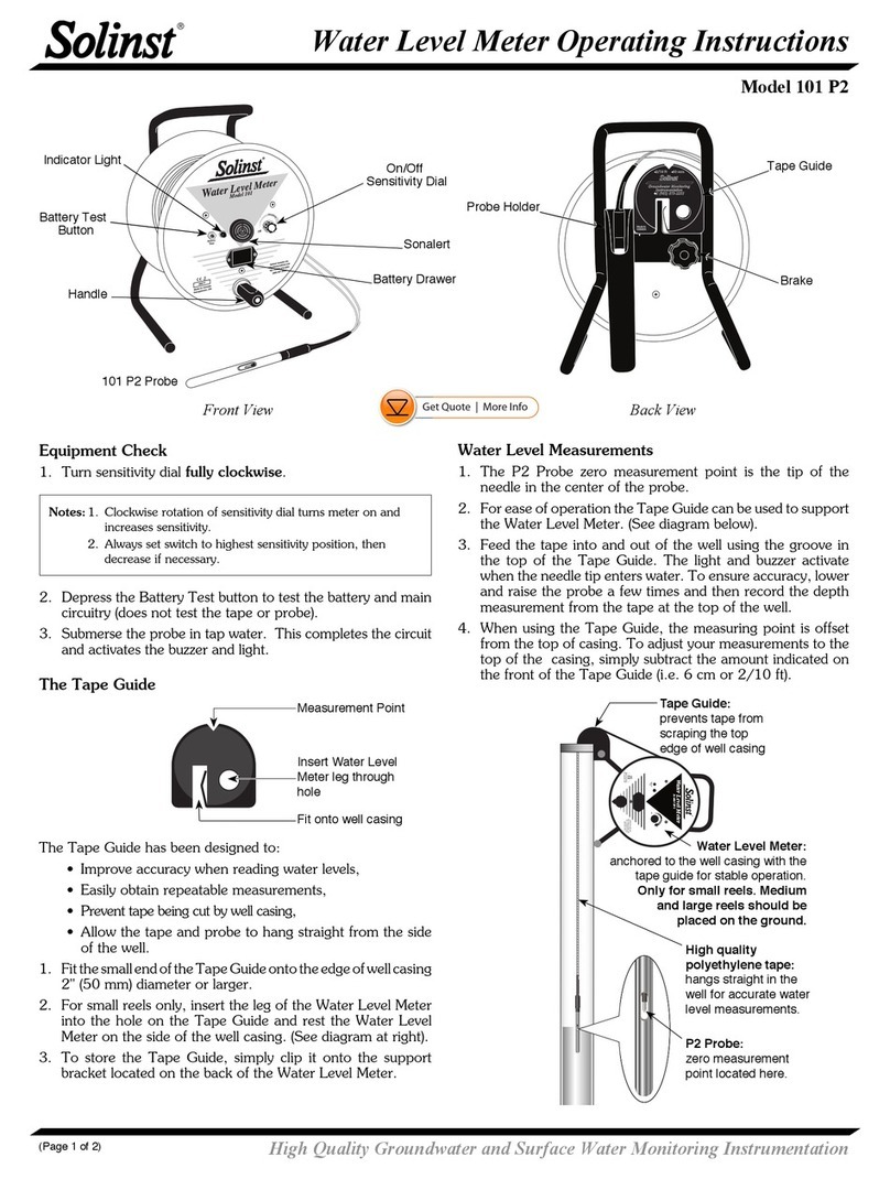
Solinst 101 P7 SC1000 User manual

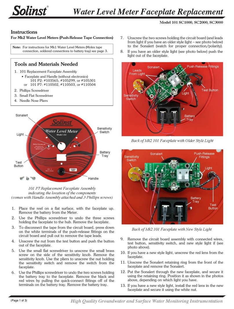
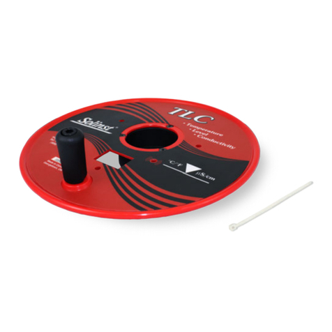
Water Level Meter Faceplate with Electronics Replacement
High Quality Groundwater and Surface Water Monitoring Instrumentation
(Page 1 of 2)
Model 101/102
Instructions
1. Place the reel on a flat surface, with the faceplate up.
Remove the battery from the Meter.
Tools and Materials Needed
1. One of the following Replacement Mk2 Faceplates with
Electronics
• #112765 - 101 P7 SC1000 Faceplate w Electronics
• #112759 - 101 P7 SC2000 Faceplate w Electronics
• #112670 - 101 P2 SC1000 Faceplate w Electronics
• #112656 - 101 P2 SC2000 Faceplate w Electronics
• #114951 - 102 SC1000 Faceplate w Electronics
• #114851 - 102M SC100 Faceplate w Electronics
2. Phillips or Robertson Screwdriver
3. Wire Cutters (only required for Mk1 Water Level Meters –
see photo below)
4. Pliers (only required for Mk1 Water Level Meters –
see photo below))
Back of Mk2 101 Water Level Meter Faceplate
Push-Release Fittings
Back of Mk1 101 Water Level Meter Faceplate
Molex
Connector
4. To connect the new faceplate with electronics, connect the
tape/cable to the new circuit board assembly:
a) If this is a Mk2 Water Level Meter, press down on
the white terminals on the circuit board and insert the
tape/cable leads. Release the terminals and the leads
should be secured.
For 101 Water Level Meter, the negative lead on the
top of the tape (numbers facing up for P2, see note
below for P7) is inserted into the terminal with a white
square below it on the circuit board (see next page for
more images).
Continued overleaf...
Note: The battery is located inside the reel hub of a 102M Water Level
Meter. Remove it in step 2.
2. Use the screwdriver to undo the three screws holding the
faceplate to the hub. Remove the faceplate.
3. If this is a Mk1 Water Level Meter, disconnect the Molex
connector that connects the circuit board to the tape/cable.
If this is a Mk2 Water Level Meter, press down on the white
terminals of the push-release fittings on the circuit board
and pull out to remove the tape/cable leads.
Note: For the 101 P7, there is a “P” etched on the tape to help
denote the proper orientation of the tape – top (negative) and
bottom (positive) leads.
Top
Bottom
“P”
For 102 Water Level Meters, the negative lead is
inserted into the terminal with white square below it
on the circuit board. The negative pin is connected to
the black insulated braided wire. The positive lead has
the pin connected to centre wire. (see next page for
more images).
Top (negative) pin inserted into terminal with white
square below it on the circuit board.
102
1
2
9 8ft 7
More Info | Instructions | Get Quote
Solinst Canada Ltd. 35 Todd Road, Georgetown, Ontario Canada L7G 4R8 www.solinst.com
E-mail: instruments@solinst.com Tel: +1 (905) 873-2255; (800) 661-2023 Fax: +1 (905) 873-1992
February 8, 2022
(#113261) (Page 2 of 2)
Square
Remove the Pins from the Tape Molex Connector (Mk1)
Cut the Pins on Each Tape/Cable Lead in Half (as shown)
Press Down on the White Terminals on the Circuit Board and
Insert the Tape/Cable Leads
Release the White Terminals and the Leads Should be
Secured.
5. Install the battery.
6. With the probe in a glass of tap water, turn the Water Level
Meter to the ‘ON’ position. If the connections are correct
the buzzer and light will activate. If the buzzer or light do
not activate, check all connections and the polarity of the
battery.
7. Reattach the faceplate to the reel using the three screws.
b) If this is a Mk1 Water Level Meter, with a Molex
connector on the tape/cable leads, remove the Molex
connector by pushing out the two pins. Cut each pin
in half (see image for correct location).
Use pliers to flatten the remainder of the pins against
the tape/cable lead, so it fits easily into the terminals
on the circuit board. Connect each tape/cable lead to
the new circuit board assembly, as described in step a.
Molex Connector
Insulated Braided Wire
(Negative Lead)
Centre Wire
(Positive Lead) Cut Pins Here

This manual suits for next models

11

Other Solinst Measuring Instrument manuals

Solinst 101 Operating and safety instructions

Solinst

Solinst 101 Operating and safety instructions

Solinst 104 User manual

Solinst

Solinst 104 User manual

Solinst 102 User manual

Solinst

Solinst 102 User manual

Solinst Levelogger 3001 Use and care manual

Solinst

Solinst Levelogger 3001 Use and care manual

Solinst Levelogger 3001 User manual

Solinst

Solinst Levelogger 3001 User manual

Solinst 101B User manual

Solinst

Solinst 101B User manual

Solinst 101 P7 User manual

Solinst

Solinst 101 P7 User manual

Solinst 102M User manual

Solinst

Solinst 102M User manual

Solinst 9700 SolSat 5 User manual

Solinst

Solinst 9700 SolSat 5 User manual

Solinst 102 Operating and safety instructions

Solinst

Solinst 102 Operating and safety instructions

Solinst 107 Mk2 User manual

Solinst

Solinst 107 Mk2 User manual

Solinst 101 User manual

Solinst

Solinst 101 User manual

Solinst 102 Operating and safety instructions

Solinst

Solinst 102 Operating and safety instructions

Solinst Levelogger Series User manual

Solinst

Solinst Levelogger Series User manual

Solinst 101 Operating and safety instructions

Solinst

Solinst 101 Operating and safety instructions

Solinst 122 User manual

Solinst

Solinst 122 User manual

Solinst 102M User manual

Solinst

Solinst 102M User manual

Solinst 122M User manual

Solinst

Solinst 122M User manual

Solinst 401 User manual

Solinst

Solinst 401 User manual

Solinst 101D User manual

Solinst

Solinst 101D User manual

Solinst 101 P2 Operating and safety instructions

Solinst

Solinst 101 P2 Operating and safety instructions

Solinst 101M User manual

Solinst

Solinst 101M User manual

Solinst 101 P2 User manual

Solinst

Solinst 101 P2 User manual

Solinst 615 ML User manual

Solinst

Solinst 615 ML User manual

Popular Measuring Instrument manuals by other brands

SKC 224-6580 operating instructions

SKC

SKC 224-6580 operating instructions

Voltmaster FCM1 operating manual

Voltmaster

Voltmaster FCM1 operating manual

PRUFTECHNIK VIBTOOL operating instructions

PRUFTECHNIK

PRUFTECHNIK VIBTOOL operating instructions

PeakTech 9015 Operation manual

PeakTech

PeakTech 9015 Operation manual

Conant VRG7-2LFB Assembly instructions

Conant

Conant VRG7-2LFB Assembly instructions

Chauvin Arnoux AEMC True Megohmmeter 3528 user manual

Chauvin Arnoux

Chauvin Arnoux AEMC True Megohmmeter 3528 user manual

National Instruments SA1000X manual

National Instruments

National Instruments SA1000X manual

Radio Shack Sound Level Meter owner's manual

Radio Shack

Radio Shack Sound Level Meter owner's manual

Ryobi RLM30 Original instructions

Ryobi

Ryobi RLM30 Original instructions

Endress+Hauser Liquiline To Go CYM290 operating instructions

Endress+Hauser

Endress+Hauser Liquiline To Go CYM290 operating instructions

Deviser DS2400T Operation manual

Deviser

Deviser DS2400T Operation manual

IDEAL 61-557 manual

IDEAL

IDEAL 61-557 manual

Medrad Veris 8600 Operation manual

Medrad

Medrad Veris 8600 Operation manual

Agilent Technologies E8362A Service guide

Agilent Technologies

Agilent Technologies E8362A Service guide

HOKUYO AUTOMATIC UBG-05LN instruction manual

HOKUYO AUTOMATIC

HOKUYO AUTOMATIC UBG-05LN instruction manual

General Sleep Zmachine Insight+ DT-200 Service manual

General Sleep

General Sleep Zmachine Insight+ DT-200 Service manual

Fluke OptiView Series Getting started guide

Fluke

Fluke OptiView Series Getting started guide

ProtEX-RTP PD6830 series instruction manual

ProtEX-RTP

ProtEX-RTP PD6830 series instruction manual

manuals.online logo
manuals.online logoBrands
  • About & Mission
  • Contact us
  • Privacy Policy
  • Terms and Conditions

Copyright 2025 Manuals.Online. All Rights Reserved.