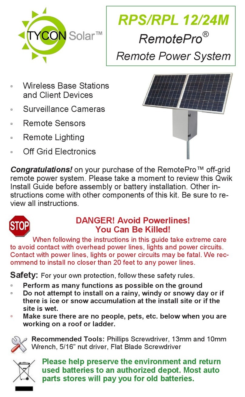
TYCON Solar UPSPro UPS-PL-120 LG User manual
Other TYCON Solar Power Supply manuals
TYCON Solar
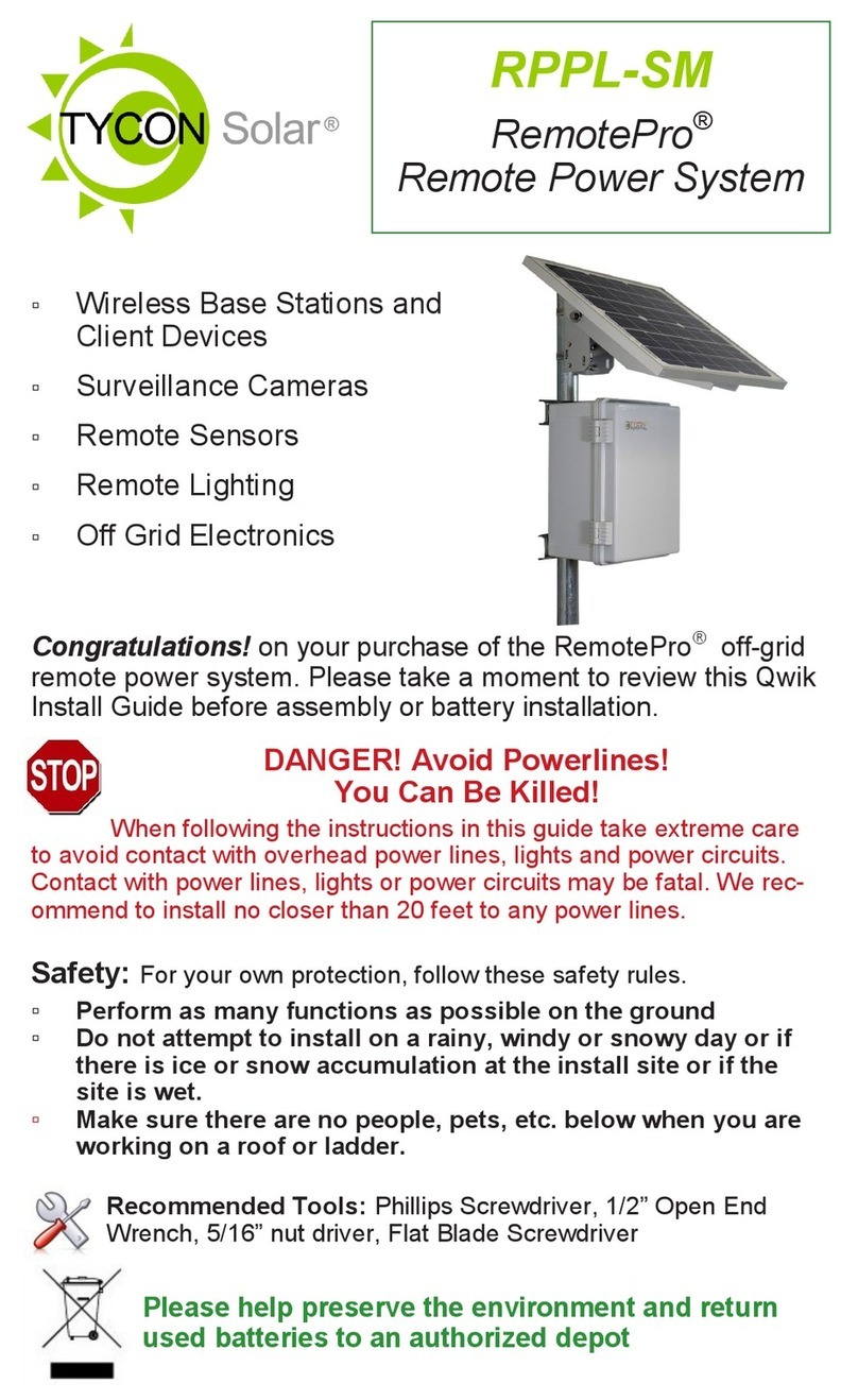
TYCON Solar RemotePro RPPL-SM User manual

TYCON Solar
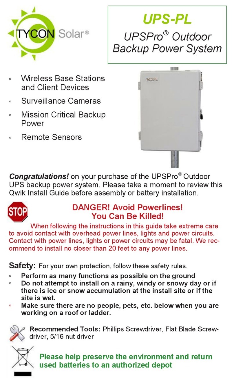
TYCON Solar UPSPro UPAL24/48-900 User manual
TYCON Solar
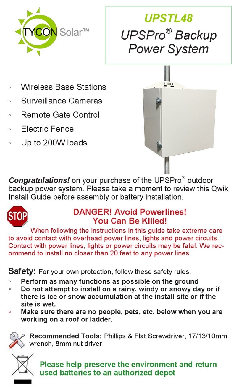
TYCON Solar UPSPro UPS-PL User manual
TYCON Solar
TYCON Solar UPSPro UPSTL48 User manual
TYCON Solar
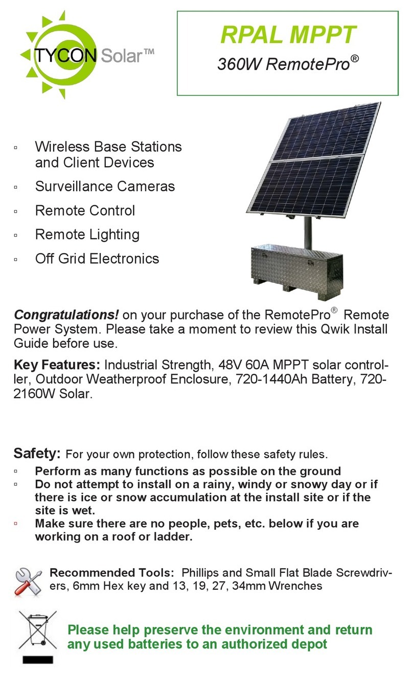
TYCON Solar RemotePro RPAL MPPT User manual
TYCON Solar
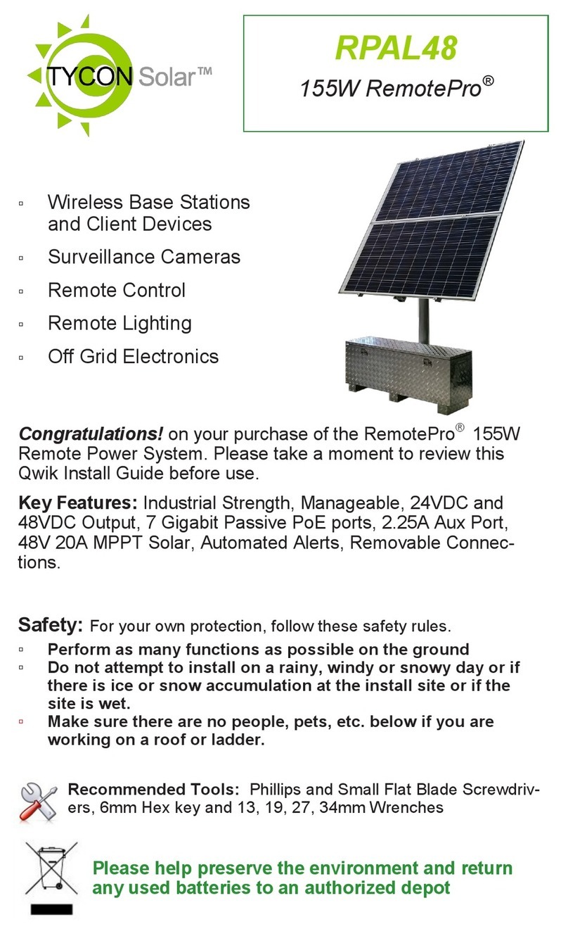
TYCON Solar RemotePro RPAL48 User manual

TYCON Solar
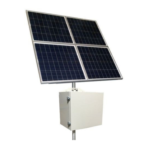
TYCON Solar RemotePro RPPL User manual
TYCON Solar
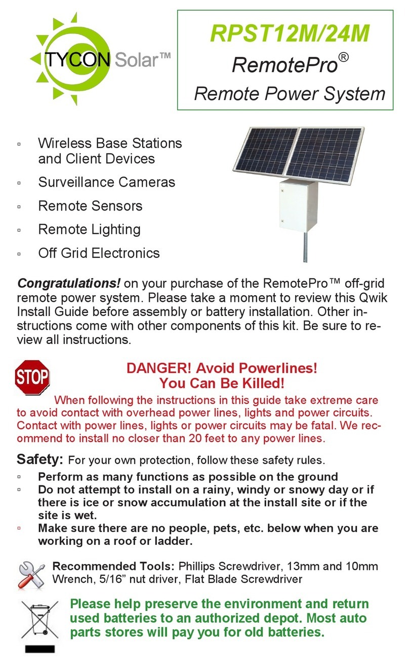
TYCON Solar RemotePro RPSTL 12 User manual
TYCON Solar
TYCON Solar RemotePro RPST12M User manual

TYCON Solar
TYCON Solar UPSPro UPS-STL-500 User manual
Popular Power Supply manuals by other brands

Videx
Videx 520MR Installation instruction

Poppstar
Poppstar 1008821 Instructions for use

TDK-Lambda
TDK-Lambda LZS-A1000-3 Installation, operation and maintenance manual

TDK-Lambda
TDK-Lambda 500A instruction manual

Calira
Calira EVS 17/07-DS/IU operating instructions

Monacor
Monacor PS-12CCD instruction manual


