Tymate TM527M Installation instructions

Tire Pressure Monitoring System
User Instruction
Implementation Standard: GB26149-2017

1. Product Overview
1.1 Product Introduction
1.2 Safety Warnings
1.3 Installation Precautions
2. Product Features
3. Product Compositions
3.1 Monitor Buttons and LCD Image
4. Installation Guides
4.1 Monitor Installation
4.2 Sensor Installation
5. Parameter Settings
5.1 Factory Settings
5.2 Setting Order
6. Alarm Status
6.1 High Pressure Alarm
6.2 Low Pressure Alarm
6.3 High Temperature Alarm
6.4 Sudden Air Leak Alarm
6.5 Low Voltage Alarm of the Sensor Battery
7. Other Functions
8. User Code
9. Technical Parameters
10. The Disclaimer
11. Some Using Tips
12. Contact Us
01
01
01
02
02
03
03
04
04
04
07
07
07
09
09
19
10
10
11
11
11
12
12
13
14

1. Product Overview
1.1.1 Product Introduction
Thank you for choosing our tire pressure monitoring system, which is composed of
sensors and monitor.
The system is used to detect the air pressure and temperature of each tire in real time.
The collected pressure and temperature data will be sent to the monitor by means of
radio frequency. After the data is received and processed by the monitor, it will be shown
on the monitor screen to remind the user to avoid traffic accidents. The corresponding
alarms will be issued for different abnormal situations according to the standard pressure
and temperature alarm values set by the user.
The system can improve the comfort of the vehicle, reduce fuel consumption and vehicle
wear, improving dynamic performance.
Be sure to read the user instruction carefully before installation and keep the
instruction for future use. Thank you!
1.1.2 Safety Warnings
Before installing the product, please read the following precautions.
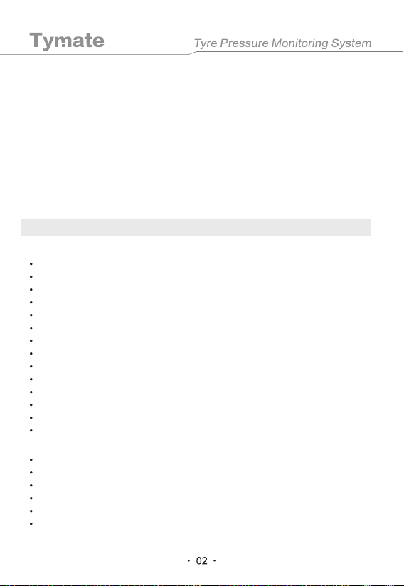
1.2.1 The monitor should be installed in a location where it will not affect the driving vision.
1.2.2 The monitor should be reinforced to avoid falling during driving.
1.2.3 While driving, if the tire temperature rises sharply, the tire pressure will also rise
accordingly. If the temperature exceeds the warning value, stop the car to let it dissipate
the heat naturally to prevent brake failure or tire burst.
1.2.4 If the pressure continues to rise or drop at an accelerated rate while driving, stop to
check for air leaks or other problems.
1.2.5 When the air pressure is too high, you should be aware of a tire blow out. When
the air pressure is too low, you should pay attention to fuel consumption and balance.
1.2.6 This product can effectively monitor the tire pressure and temperature in real time,
but cannot avoid traffic accidents or tire blowouts. Using high-quality tires is as important
as this product to ensure that the tire pressure is normal.
1.2.7 When checking the displayed pressure and temperature values, please pay
attention to driving safety.
1.2.8 This product will automatically detect the tires and sound an alarm in case of
abnormal situations, so that the driver does not need to pay frequent attention to it so as
not to be distracted while driving.

Monitor
Sensor
1.3 Installation Precautions
1.3.1 There is a wireless connection between the sensor and the monitor. The
transmission distance of them is far enough. Designed with multiple anti-interference
functions, the possibility of interference to the sensor and the monitor is extremely low.
1.3.2 During the driving process, due to the thermal expansion and contraction of the air,
the tire pressure and temperature will get higher or lower, which is normal.
1.3.3 In general, tires have normal natural air leaks. The tire pressure will decrease over
time, which is a normal phenomenon and has no direct relationship with the installation of
this product.
1.3.4 If you have any problems with installation, please contact the agent or distributor.
2. Product Features
LED Color Display
Excessive Pressure and Temperature Alarm
Visual & Audible Alarm
Multiple Pressure Unit Options (PSI, BAR)
Multiple Temperature Unit Options (˫/ ˭)
Setting Standard Alarm Values for the Tire Pressure and Temperature
Arbitrary Interchangeability of Tire Positions
Automatically Turning on the Monitor Backlight
Supporting up to Four Tires
Showing the Pressure or Temperature of Four Tires Simultaneously
Sudden Air Leak Alarm
Waterproof Design in the Monitor
An Independent ID Code for Each Sensor
Easy Installation and Stable Performance
External Valve Sensor, Easy Installation and Stable Performance
Designed with the Waterproof Function
Sudden Air Leak Detection and Alarm Function
Special Installation Fixture Needed to Install the Anti-theft Design
Replacing the Sensor Battery to Extend the Life span of the Sensor and Make it Easy to Use
Unique ID Code for Each Sensor

3. Product Composition
3.1 Monitor Buttons and LCD Image
Tires
DescriptionIcon
Low Voltage Alarm of the Sensor Battery
Monitor Battery Symbol
High Temperature Alarm
Fault Icon
High Pressure Alarm
Low Pressure Alarm
Sudden Air Leak Alarm
Car Battery Symbol
Down Key
Charge Socket
Pressure Unit Option: BAR or PSI
Temperature Unit Option: ˫or ȯ
SET Key Up Key

4.1 Monitor Installation
4.2 Sensor Installation
Install the monitor in a place where it is easy to see in the car. The user can directly paste
the monitor on the dashboard with double-sided tape or put up a suction cup in the
appropriate position of the windshield to attach it. Then connect one end of the cigarette
lighter charger to the monitor and the another end to the cigarette lighter in the car to
power it on.
1. The monitor should be installed in a position where it will not affect the driving vision.
2. The monitor should be reinforced to avoid falling during driving.
3. When checking the displayed pressure and temperature values while driving, please
pay attention to driving safety .
4. This product will automatically detect the tires and sound an alarm, so the driver does
not need to pay frequent attention to it so as not to be distracted while driving.
The sensor ID code has been paired before leaving the factory. The sensor can be
installed on the tire directly at the corresponding position when installing, and can be used
directly. The standard configuration is one monitor paired with 4 sensors,and each
sensor uses stickers (front left, rear left, front right, rear right) to indicate the
corresponding tire position. If there is a spare tire in the vehicle, a sticker (backup) is
required to indicate the position of the spare tire. When installing, please carefully read the
user instruction to paste the label stickers (as shown in Figure 2) to corresponding tires.
4. Installation Guides
Notice:
Corresponding Tire Position Diagram for Sensor Installation:

Installation Position Diagram:
Please install the monitor and sensor that have been equipped at the factory into the
vehicle. If there is an error code or the position of the sensor is forgotten during the
assembly process, you can re-code with the "inflatable code". (Refer to the user instruction
of the monitor for details on the operation of the inflatable code.)
Notice:
Notice:
Before installing the sensor, please make sure to turn on the monitor so that the data can
be sent to the monitor in time after the sensor is installed.
Notice:
1. Each sensor uses a sticker to indicate its tire position, and it must be accurately
installed on the corresponding tire.
2. When the voltage of the sensor battery is low, there will be a low voltage alarm on the
monitor.
3. After the sensor is installed, please check whether there is any air leak in the tire. If
necessary, use soapy water to wipe the tire valve to check.
1. First install the anti-theft hex nut into the thread of the car tire valve core.
2. Tighten the transmitter clockwise to the thread of the car tire valve core.
3. Use a clamp to tighten the anti-theft hex nut counterclockwise to the transmitter to
activate the anti-theft function.
The sensor installation steps are as follows.
Figure 2
Front Left Front Right
Rear Left Rear Right
Anti-theft Hex Nut
Anti-theft Hex Nut
Tire Valve Core
Transmitter

The steps for replacing the sensor battery are as follows.
1. Use power tools to fasten the upper cover of the sensor and the tire valve respectively,
and twirl the sensor housing counterclockwise.
2. Take out the battery from the battery clamp.
3. Install a new lithium battery CR1632 with the positive pole (+) facing upwards.
4. Screw on the sensor housing, and then use a power tool to tighten it clockwise.
Notice:
When installing the sensor housing, be sure to check whether the waterproof rubber ring is
in place. If it is damaged, please replace it with a new one before installing the housing.
Power Tool
The Negative Pole
Lithium Battery CR1632
The Positive Pole
Lithium Battery CR1632
Waterproof
Rubber Ring

5.1 Factory Settings
5.2 Setting Order
5.2.1 Pressure Unit setting
5.2.2 Temperature Unit Setting
In the standby mode, press and hold the "SET" key on the monitor. Release it after the
first beep sound, and the monitor will enter the first setting interface, and the correspond-
ing LCD symbol will flash. Then press the "SET" key to select the parameter item that
needs to be set, and press "-" or "+" to set specific parameter values. After the setting is
completed, press and hold the "SET" key and release it when you hear a beep sound. In
this way, you can save the parameters and exit to the normal standby state. When
entering the setting state, press "-" or "+" at the same time to exit the setting mode without
saving the setting data. If there is no operation within 1 minute in the setting state, the
system will automatically exit the setting mode and return to the normal standby state. The
setting order of parameter 1-7 is as follows.
When the "PSI" or "BAR"
icon is flashing, press the
"-" or "+" key to select the
pressure unit of "PSI" or
"BAR" as desired.
When the "˫" or "˭" icon
is flashing, press the "-" or
"+" key to select the
temperature unit of "˫" or
"˭" as desired.
5. Parameter Settings
Pressure Unit
High Pressure Alarm Value
Low Pressure Alarm Value
Temperature Unit
High Temperature Alarm Value
PSI
3.0BAR (44PSI)
2.0BAR (29PSI)
°C
70°C

5.2.3 High Pressure Alarm Value Setting of the Front Tire (UP)
5.2.4 Low Pressure Alarm Value Setting of the Front Tire (DO)
When the high pressure parameter and the front
tire icon are flashing, press the "-" or "+" key to
select the high pressure alarm value required by
the user.
When the low pressure parameter and the front
tire icon are flashing, press the "-" or "+" key to
select the low pressure alarm value required by
the user.
5.2.5 High Pressure Alarm Value Setting of the Rear Tire (UP)
When the high pressure parameter and the rear
tire icon are flashing, press the "-" or "+" key to
select the high pressure alarm value required by
the user.
5.2.6 Low Pressure Alarm Value Setting of the Rear Tire (DO)
When the low pressure parameter and the rear
tire icon are flashing, press the "-" or "+" key to
select the low pressure alarm value required by
the user.
5.2.7 High Temperature Alarm Value Setting (UP)
When the high temperature parameter is
flashing, press the "-" or "+" key to select the
high temperature alarm value required by the
user.

6.1 High Pressure Alarm
High Pressure Alarm/ Low Pressure Alarm/ High Temperature Alarm/ Sudden Air
Leak Alarm/ Low Voltage Alarm of the Sensor Battery
The same interface of the monitor shows the pressure and temperature of 4 tires. When
the tire pressure or temperature exceeds the safety range set by the user, the
corresponding tire icon, parameter and corresponding fault icon on the monitor screen will
flash and sound a warning alarm. Press any key to cancel the alarm sound but the
corresponding tire icon, parameter and corresponding fault icon will continue to flash until
all the tire faults are resolved.
For example, when the left front tire pressure value is 45PSI, the monitor will show the
picture below with a warning sound (Bi...Bi...Bi...).
6.2 Low Pressure Alarm
For example, when the left front tire pressure value is 28PSI, the monitor will show the
picture below with a warning sound (Bi...Bi...Bi...).
6. Alarm Status
The barometric pressure
reading flashes.
The fault icon flashes.
The high pressure
alarm icon flashes.
The tire icon flashes.
The barometric pressure
reading flashes.
The fault icon flashes. The low pressure
alarm icon flashes.
The tire icon flashes.

6.3 High Temperature Alarm
For example, when the temperature of the front left tire is 159 , the monitor will show the
picture below with a warning sound (Bi...Bi...Bi...).
The temperature
reading flashes.
The fault icon flashes.
The high temperature
alarm icon flashes.
The tire icon flashes.
6.4 Sudden Air Leak Alarm
When the sensor detects a sudden air leak, it will immediately send alarm data to the
monitor. The corresponding tire icon, barometric pressure reading, and fault icon on the
monitor will flash with a warning sound (Bi......). Press any key to cancel the alarm sound.
However, the tire icon, barometric pressure reading, and fault icon will continue to flash,
and the normal data cannot be restored until all the tire faults are eliminated.
For example, when the pressure of the front left tire drops from 34 PSI to 29 PSI
immediately, the monitor will show the picture below with a warning sound (Bi...Bi...Bi...).
The barometric pressure
reading flashes.
The fault icon flashes.
The tire icon flashes.
The sudden air leak alarm icon flashes.
6.5 Low Voltage Alarm of the Sensor Battery
When the sensor detects that the battery is in low voltage, it will immediately send alarm
data to the monitor. The corresponding tire icon and low voltage icon on the monitor will
flash with a warning sound (Bi...Bi...Bi...). Press any key to cancel the alarm sound. But
the low voltage icon and tire icon will continue to flash until the sensor is replaced with a
new battery.
For example, when the voltage of the sensor of the right rear tire is too low, it will show the
picture below.
The low voltage alarm of the
sensor battery icon flashes.
The fault icon flashes.
The tire icon flashes.

Pressure display converts to temperature display.
Inflatable Code
7. Other Functions
8. User Code
When the pressure interface is displayed, press the "SET" key once to switch to the
temperature display interface. The temperature display interface will automatically switch
to the pressure display interface after 10 seconds.
The monitor diagram is as follows.
The 4 sensors have been coded and marked with the tire positions before leaving the
factory. The user only need to install the corresponding sensors to the corresponding tires.
When the user needs to exchange the tires, or there is a wrong code, or the position of the
sensor is forgotten during the assembly process, the following "inflatable code" is
available for the user to re-code.
In the standby mode, press and hold the "+" button on the monitor and release it after a
beep sound. The system will enter the inflatable code interface, and the LCD current tire
icon flashes, showing the "Id" and 6-digit ID code of the current tire. Short press the "-"
key to select the tire position that needs to be coded, and then install the sensor on the
corresponding tire (external sensor), or install the built-in sensor and then inflate the
corresponding tire (built-in sensor). When the sensor senses the inflation, it will alarm with
a beep sound and then the ID code of the sensor will be displayed (as shown in the figure
below), which indicates that the tire ID code has been aligned. Use the same method to
match the code with other sensors. When all the required ID codes have been
successfully received, press and hold the "SET" key on the monitor. Release the key after
a beep sound, save the ID code to the monitor and exit to normal working state. Press the
"-" and "+" keys at the same time to exit to the normal working state without saving the ID
code.
Manually adjust the backlight and turn off the monitor interface.
Short press the "-" or "+" key to adjust the brightness of the backlight or turn off the
monitor interface.
10s

Monitor
9. Technical Parameters
10. The Disclaimer
10.1 Please use this product correctly and use it within its allowable range. If it is used
beyond its scope, the company will not be responsible for all the consequences.
10.2 The installation process should strictly follow the instructions of the user instruction. If
any damage caused by the installation that does not follow the instructions, the company
will not be responsible for the consequences or give any explanation.
10.3 When setting the alarm value, please strictly abide by its range. Different models
should be set according to the tire parameters or the manuals, or the range given by the
agents or dealers. (Generally, if the system is set up, there is no need to modify it in the
future). If there is any product failure caused by self-setting or improper settings, the
company does not bear any responsibility for it.
10.4 The content in this instruction will be subject to change without prior notice. The
pictures in this instruction are just for illustration. Please refer to the actual product.
10.5 Be sure to ask an experienced tire installation technician to install the product. When
you need to disassemble the tire again, please be careful not to damage the sensor.
The tire icon flashes.
For example, the ID code of the left front tire is 83A512.
Working Temperature
Storage Temperature
Voltage
Frequency
Dimension (L*W*H)
Weight
Pressure Setting Range
Temperature Setting Range
Pressure Monitor Range
Temperature Monitor Range
-20˫~80˫
-30℃~ 85˫
DC 12~24V
433.92 MHz
76*50*22 mm
58g
15~144 PSI (1.0~9.9 BAR)
77~212˭(25~100˫)
0~87 PSI (0~6 BAR)
-104~176˭(-40~80˫)

Please note that the following conditions are normal in product use.
---IF THE SENSOR IS NOT IN THE NORMAL OPERATION---
11.1 The data updating time of the sensor is about 5 minutes. And if you change the
sensor to another wheel, the previous data may stay for a while. If the sensor is removed,
there will still be data staying on the monitor. It is normal, and it may take up to 2 hours for
the monitor to completely disappear after hours of data displayed.
11.2 There will be a slight air leak in the tire after the sensor is installed. It is normal.
Please rest assured to use it.
11.3 It is normal for the sensor to be worn and corroded by the external environment. We
recommend that you buy extra sensors as backup. When the sensor is abnormal, you can
try to solve the problem according to the following instructions. If the problem persists, you
can contact us for after-sales service to get the replacement sensor.
It is recommended to test the sensor first. You could take off the sensor from your tire to
see if the machine alarms.
1. If the monitor begins beeping, it means your sensor is in normal operation. Then you
could try to re-install the sensor. If it still does not work, maybe the sensor lacks battery
power. Then you could try another battery again. And here I would like to provide a
change-battery video to help you. The video link is as follows: https://youtu.be/JXc0sV -
jN19Y
2. If it does not alarm, it may also mean that the sensor lacks battery power. You could try
another new battery again. The battery-change video is mentioned above, and you could
refer to it.
11.4 It is normal for the tire pressure monitor to measure the tire pressure with a certain
degree of accuracy (when you find that its measurement result is different from your tire
pressure gauge).
11. Some Using Tips

We promise 2-YEAR WARRANTY and 24/7 CONSIDERATE CUSTOMER SERVICE. If
<+1(855)492-9277> directly. You can quickly get in touch with the after-sales team by
scanning the QR code below. It’s also a good choice to contact us by after-sales service
official website: https://tymate.afterservice.vip
The TPMS monitors the tire pressure and temperature referring to their variations per unit
time. And the tire pressure gauge monitors the tire pressure by getting the instantaneous
data. So it is normal that when you use two different measuring tools, you would get two
data which has a little deviation. But these two different data are referenceable.
12. Contact Us
---IF THE DEVICE SEEMS LIKE IT COULD NOT MONITOR
THE TIRE PRESSURE ACCURATELY---
If you find the tire pressure that the monitor displays is not accurate, there are two
different possible reasons that could explain this issue.
1. The feature of needing some minutes to update the data
Our TPMS will receive real-time signals. In general, the monitor will update every 5
minutes. You could wait for a minute and then confirm if the reading is correct.
2. Different measuring tools may cause some deviation in the normal range (if you use a
tire pressure gauge to compare with it). The theory of measurement between two devices
is different. Here is the operation theory of the TPMS and of the tire pressure gauge.

Table of contents