manuals.online logo
Brands
  1. Home
  2. •
  3. Brands
  4. •
  5. Fortin
  6. •
  7. Automobile Accessories
  8. •
  9. Fortin EVO-ALL User manual

Fortin EVO-ALL User manual

* HOOD PIN HOOD STATUS : THE HOOD PIN SWITCH MUST BE INSTALLED
IF THE VEHICLE CAN BE REMOTE STARTED WITH THE HOOD OPEN,
SET FUNCTION A11 TO OFF.
CONTACT
DE CAPOT
MANDATORY INSTALL | INSTALLATION OBLIGATOIRE Notice: the installation of safety
elements are mandatory. The hood pin
is an essential security element and
must be installed.
Notice: l'installation des éléments de
sécurité est obligatoire. Le contact de
capot est un élément de sécurité
essentiel et doit absolument être
installé.
THIS MODULE MUST BE INSTALLED BY A
QUALIFIED TECHNICIAN. A WRONG
CONNECTION CAN CAUSE PERMANENT
DAMAGE TO THE VEHICLE.
CE MODULE DOIT ÊTRE INSTALLÉ PAR
UN TECHNICIEN QUALIFIÉ, TOUTE
ERREUR DANS LES BRANCHEMENTS
PEUT OCCASIONNER DES DOMMAGES
PERMANENTS AU VÉHICULE.
STATUT DE CAPOT : LE CONTACT DE CAPOT, DOIT ÊTRE INSTALLÉ SI LE
VÉHICULE PEUT DÉMARRER À DISTANCE, LORSQUE LE CAPOT EST OUVERT,
PROGRAMMEZ LA FONCTION A11 À NON.
A11 OFF
NON
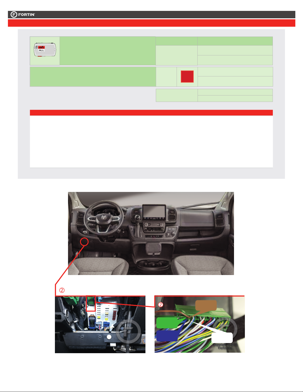
ADDENDUM - SUGGESTED WIRING CONFIGURATION
ADDENDA - SCHÉMA DE BRANCHEMENT SUGGÉRÉ
ALL REV.: 20230921
NOTES
The vehicle’s OEM remote lock/Unlock and
vehicle’s OEM proximity remote will remain
functional while the engine is running.
La télécommande d’origine Verrouille/Déverrouille et la télécommande
de proximity d’origine du véhicule du véhicule sera fonctionnelle pendant
que le véhicule est en marche.
Guide # 108881
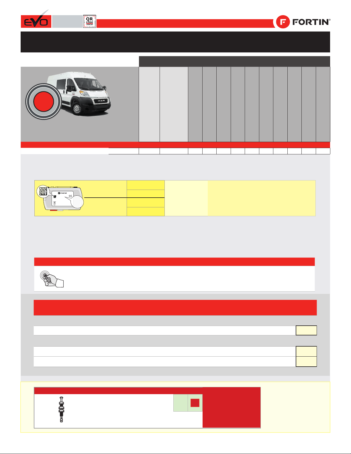
Vehicle functions supported in this diagram (functional if equipped) | Fonctions du véhicule supportées
dans ce diagramme (fonctionnelles si équipé)
Immobilizer bypass
Contournement d’immobilisateur
T-Harness
Harnais en T
Lock
Unlock
Arm
Disarm
Tachometer
Door Status
Hood Status
Hand-Brake Status
Foot-Brake Status
OEM Remote monitoring
VEHICLE
VEHICULES
YEARS
ANNÉES
RAM
ProMaster
Push-to-start
2022-2023
•
•
•
•
•
•
•
•
•
•
•
•
PUSH
START
Parts required (Not
included)
Pièce(s) requise(s) (Non
incluse(s)) PAGE
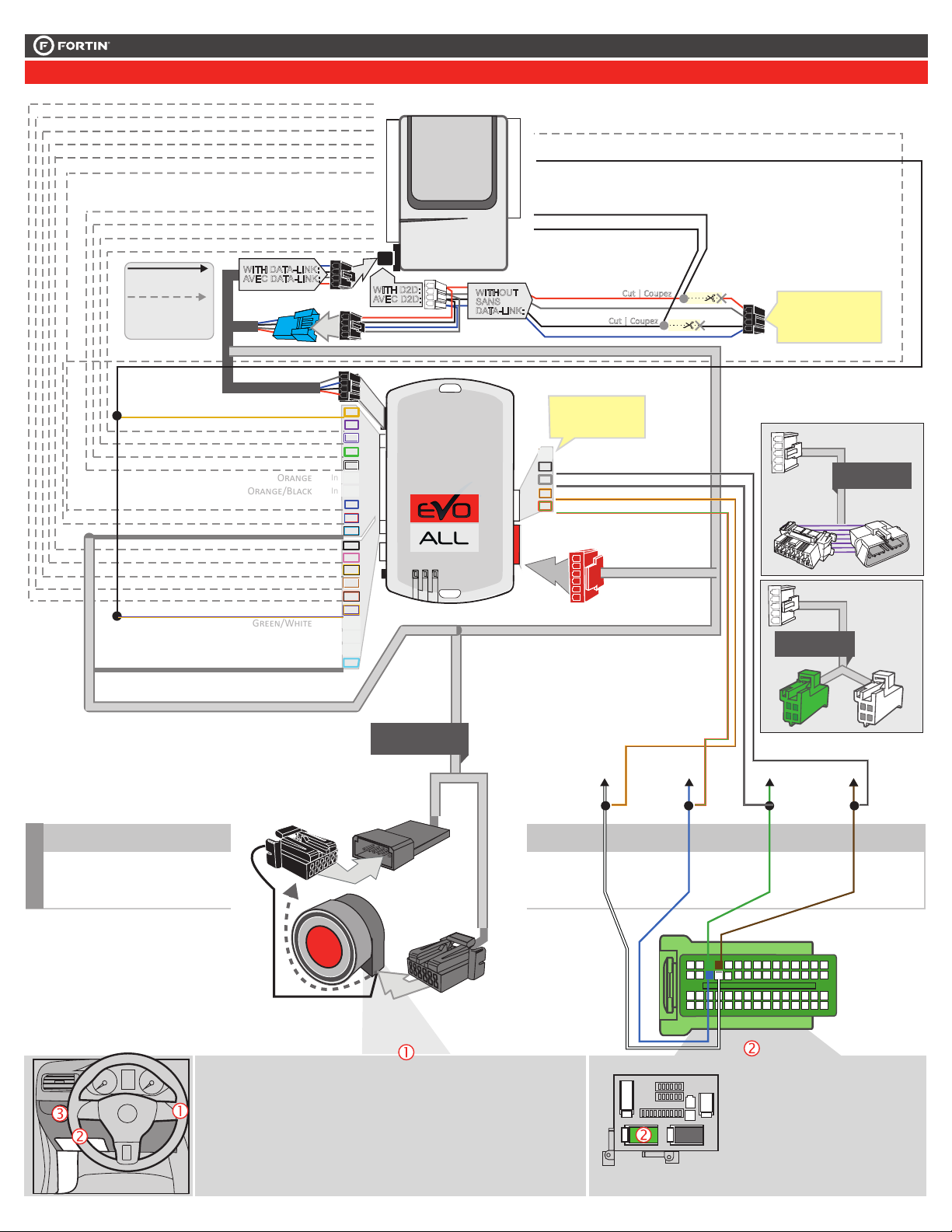
WIRE TO WIRE DIAGRAM | SCHÉMA DE BRANCHEMENTS FIL À FIL
1x fuse 1x Fusible Page 3
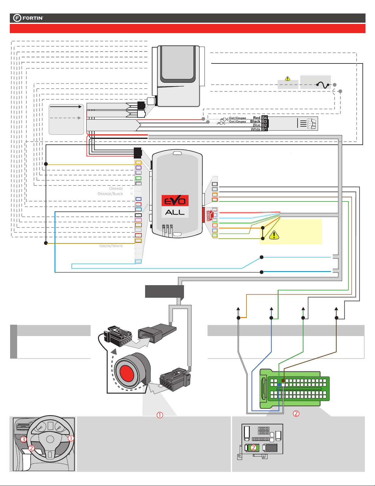
THARNESS DIAGRAM | SCHÉMA DE BRANCHEMENTS HARNAIS EN T
THARNESS THAR-CHR7 1x THAR-CHR7 1x THAR-CHR7 Page 4
THARNESS THAR-CHR6 1x THAR-CHR6 1x THAR-CHR6 Page 5
MODEL: EVO-ALL
DATE:02/2019
FORTIN.CA
SN: 000000 00000
MADE IN CANADA
© 2018 ALL RIGHTS RESERVED 2019
COMPATIBLE
MODULE
REQUIRED:
QR CODE
ON THE LABEL FIRMWARE VERSION
VERSION LOGICIELLE
To add the rmware version and the options, use the
FLASH LINK UPDATER or FLASH LINK MOBILE tool,
sold separately.
Pour ajouter la version logicielle et les options,
utilisez l’outil FLASH LINK UPDATER
ou FLASH LINK MOBILE, vendu séparément.
MANUFACTURED
AFTER: 2019
MODULE
COMPATIBLE
REQUIS:
CODE QR SUR
L’ÉTIQUETTE 68.[06]
FABRIQUÉ APRÈS:
2019 MINIMUM
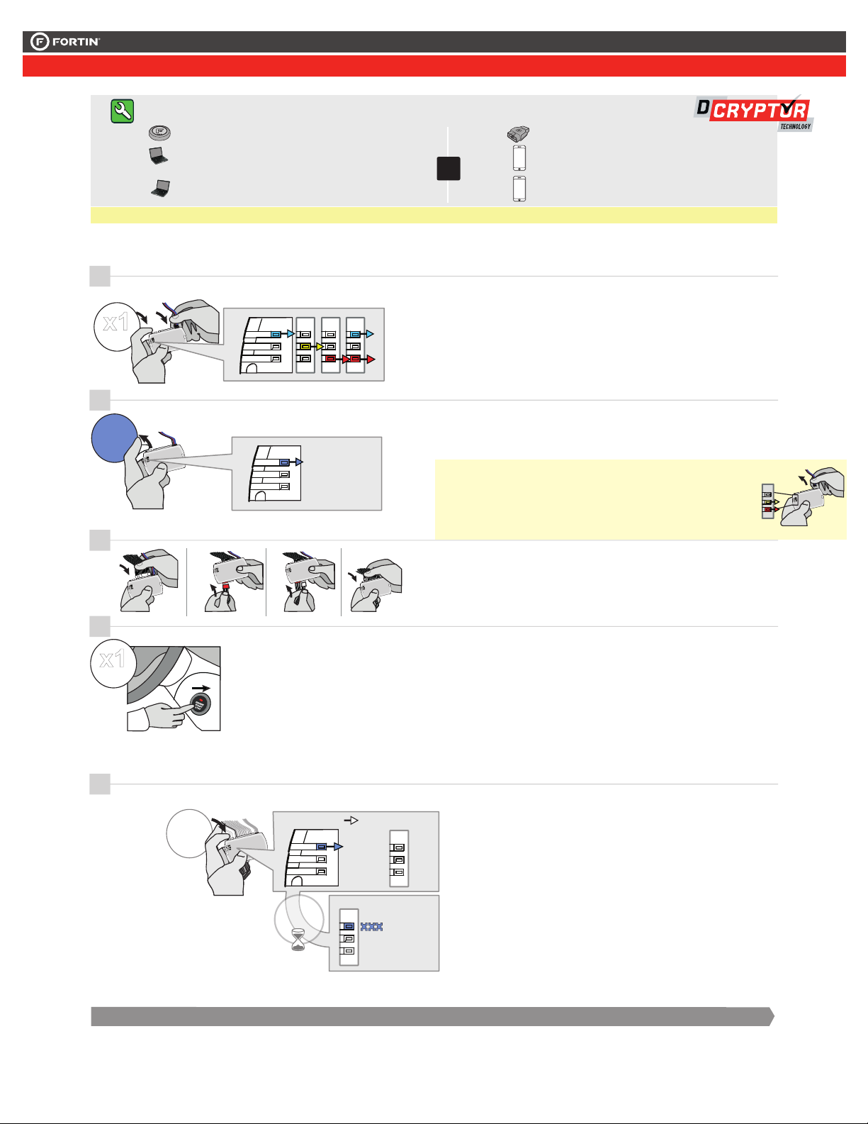
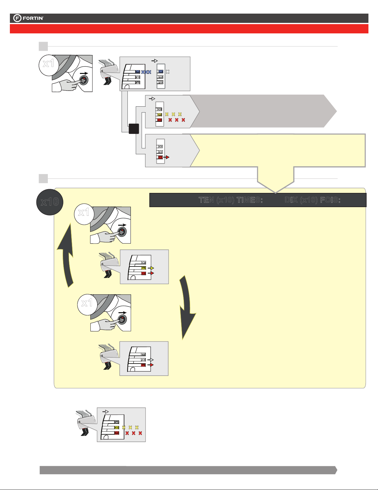
Supported functions & Function programming | Fonctions supportées et programmation des fonctions
REGULAR, THAR-CHR7 & THAR-CHR6 INSTALLATION
INSTALLATION RÉGULIÈRE, THAR-CHR7 ET THAR-CHR6
Page 1 / 10
This guide may change without notice. See www.fortin.ca for latest version.
Ce guide peut faire l’objet de changement sans préavis. Voir www.fortin.ca pour la récente version.
2-PagesSuivantes
NOTES
Program bypass option:
Programmez l’option du contournement:
UNIT OPTION
OPTION UNITE DESCRIPTION
C1
OEM Remote status (Lock/Unlock)
monitoring
Suivi des status (Verrouillage/Déverrouil-
lage) de la télécommande d’origine
IF THE VEHICLE IS NOT EQUIPPED
WITH FUNCTIONAL HOOD PIN:
SI LE VÉHICULE N’EST PAS ÉQUIPÉ
D’UN CONTACT DE CAPOT FONCTIONNEL:A11 OFF
NON
Hood trigger (Output Status).
Contact de capot (état de sortie).
NOTES 12V BATTERY | 12V BATTERIE
ATTENTION THE T-HARNESS CURRENT
IS LIMITED AT 5 AMP MAXIMUM.
If a parking lights (+) wire is use : that require more than
5Amp. Connect the remote-starter’s power directly to the
vehicles battery with the appropriate fuse.
Some remote starters can not be powered through Data-Link.
In these cases connect the remote starter’s fused 12V power
wire directly to the T-Harness.
ATTENTION LE COURANT DU 12V PROVENANT DU HARNAIS-
EN-T EST LIMITÉ À 5 AMPÈRES MAXIMUM.
Si le l des lumières de stationnement (+) est utilisé: il requière plus de
5 Ampères, branchez le 12V du démarreur à distance directement à la
batterie du véhicule avec le fusible approprié.
Certains démarreurs à distance NE peuvent PAS être allimentés par le
Data-Link. Dans ce cas, branchez le 12V (avec fusible) du démarreur à
distance directement au harnais-en-T.
D6 Push-to-Start
Push-to-Start
Fuse box
Boîte à fusibles
(~)CAN2
LOW
(~)CAN2
HIGH
(~)CAN1
HIGH
(~)CAN1
LOW
Page 2 / 10
This guide may change without notice. See www.fortin.ca for latest version.
Ce guide peut faire l’objet de changement sans préavis. Voir www.fortin.ca pour la récente version.
2-PagesSuivantes
Yellow In A1
Purple In A2
Purple/White In A3
Green Out A4
White Out A5
Orange In A6
Orange/Black In A7
Dk.Blue In A8
Red/Blue In A9
Lt.Blue/Black A10
Black Out A11
Pink Out A12
Yellow/Black In A13
Brown/White Out A14
Pink/Black Out A15
Purple/Yellow A16
Green/White A17
Green/Red A18
White/Black A19
Lt.Blue A20
C5 Brown
C4 Gray/Black
C3 Gray
C2 Orange/Brown
C1 Orange/Green
D6 White/Red
D5 White/Blue
D4 White/Green
D3 Yellow/Red
D2 Yellow/Blue
D1 Yellow/Green
AC
D
WIRING CONNECTION | GUIDE DE BRANCHEMENTS
CAN 1 LOW
CAN 1 HIGH
CAN 2 LOW
CAN 2 HIGH
WITH | AVEC DATA-LINK:
ALWAYS REQUIRED
TOUJOURS REQUIS
NOT REQUIRED WITH
DATALINK
NON REQUIS EN
DATA-LINK
12V BATTERY
Ground | Masse
B
REMOTE
STARTER
DÉMARREUR
À DISTANCE
WITH | AVEC DATA-LINK:
Direct connection
Branchement directe
HOOD IN RS8
(-)
HAND BRAKE IN RS9
(-)
TRUNK RELEASE
(-) OUT RS11
(+/-) IN RS12
TACHOMETER
F
OOT
B
RAKE
(+)
IN RS13
GROUND OUT WHILE RUNNING
(-) OUT RS14
TRUNK
(-)
IN RS17
DOOR
(-) IN RS18
UNLOCK
(-) OUT RS19
LOCK
(-) OUT RS20
A15
A14
A13
A12
A11
A8
A5
A4
A3
A2
A9
Ground | Masse
(-)
RS1
12V BATTERY
RS2 IN
(+)
IGNITION
RS6 IN/OUT (+)
STARTER
RS7 OUT (+)
(-) Hood Status
(-) Hand Brake
(-) Trunk Release
(-/+) Tachometer
(+) Foot Brake
(+)Start
(-) Ground While Running
(-) Trunk Status
(-) Door Status
(-) Unlock
(-) Lock
(+) Ignion
A2
A3
A4
A5
A6
A7
A8
A9
A10
A11
A12
A13
A14
A15
A16
A17
A18
A19
A20
C5
C4
C3
C2
C1
D6
D5
D4
D3
D2
D1
A1
D1
D2
D3
D5
C5
A19
A18
A17
A7
A6
ProMaster
323334353639 314445 43 42
Blue
Bleu
White
Blanc
(~) CAN1
HIGH (~) CAN1
LOW
Green
Vert Brown
Brun
(~) CAN2
HIGH
(~) CAN2
LOW
Back View
Green 60 pin Connector
At dash fuse box
Vue de dos
Connecteur Vert 60 pins
À la boîte à fusibles
10 2345679 181415 13 12 11
25 17181920212224 16232930 28 27 26
55 47484950515254 46535960 58 57 56
40 3741 38
6 5 4321
DATA (+)START/
STOP SIGNAL
A20
CUT
A10 D4
D6
Yellow/Blue
Jaune/Bleu Blue
Bleu
Back View
6-pin Black
Connector
At Push-to-Start
button.
Vuede dos
Connecteur Noir
de 6-pins
Au boutton de
démarrage.
109 11
21 345 8
12 13 15 16
6 7
14
4
16
Front View
White 16-pin
OBDII Connector
Vue de Face
Connecteur OBDII Blanc
de 16 pins
GROUND (+)12V
Black
Noir Red/Lt.Green
Rouge/Vert Pâle
DATA
(+) Start/Stop
DATA
DATA
RS2
RS1
5 Amp.
Fuse
Fusible
RS6
A1
(+) IGNITION OUT OUT
C3 C4C4C2 C1
Parts Requiered | Photo & Location | Pièces Requises | Photos & Emplacements
Page 3 / 10
This guide may change without notice. See www.fortin.ca for latest version.
Ce guide peut faire l’objet de changement sans préavis. Voir www.fortin.ca pour la récente version.
2-PagesSuivantes
Yellow In A1
Purple In A2
Purple/White In A3
Green Out A4
White Out A5
Orange In A6
Orange/Black In A7
Dk.Blue In A8
Red/Blue In A9
Lt.Blue/Black A10
Black Out A11
Pink Out A12
Yellow/Black In A13
Brown/White Out A14
Pink/Black Out A15
Purple/Yellow A16
Green/White A17
Green/Red A18
White/Black A19
Lt.Blue A20
C5 Brown
C4 Gray/Black
C3 Gray
C2 Orange/Brown
C1 Orange/Green
D6 White/Red
D5 White/Blue
D4 White/Green
D3 Yellow/Red
D2 Yellow/Blue
D1 Yellow/Green
AC
D
THAR-CHR7 | WIRING CONNECTION | GUIDE DE BRANCHEMENTS
CAN 1 LOW
CAN 1 HIGH
CAN 2 LOW
CAN 2 HIGH
B
HOOD IN RS8
(-)
HAND BRAKE IN RS9
(-)
TRUNK RELEASE
(-) OUT RS11
(+/-) IN RS12
TACHOMETER
F
OOT
B
RAKE
(+)
IN RS13
GROUND OUT WHILE RUNNING
(-) OUT RS14
TRUNK
(-)
IN RS17
DOOR
(-) IN RS18
UNLOCK
(-) OUT RS19
LOCK
(-) OUT RS20
A15
A14
A13
A12
A11
A8
A5
A4
A3
A2
Ground | Masse
(-)
RS1
12V BATTERY
RS2 IN
(+)
IGNITION
RS6 IN/OUT (+)
STARTER
RS7 OUT (+)
(-) Hood Status
(-) Hand Brake
(-) Trunk Release
(-/+) Tachometer
(+) Foot Brake
(+)Start
(-) Ground While Running
(-) Trunk Status
(-) Door Status
(-) Unlock
(-) Lock
(+) Ignion
A2
A3
A4
A5
A6
A7
A8
A9
A10
A11
A12
A13
A14
A15
A16
A17
A18
A19
A20
C5
C4
C3
C2
C1
D6
D5
D4
D3
D2
D1
A1
C5
A19
A18
A17
A7
A6
ProMaster
323334353639 314445 43 42
Blue
Bleu
White
Blanc
(~) CAN1
HIGH (~) CAN1
LOW
Green
Vert Brown
Brun
(~) CAN2
HIGH
(~) CAN2
LOW
Back View
Green 60 pin Connector
At dash fuse box
Vue de dos
Connecteur Vert 60 pins
À la boîte à fusibles
10 2345679 181415 13 12 11
25 17181920212224 16232930 28 27 26
55 47484950515254 46535960 58 57 56
40 3741 38
PUSH
START
T-HARNESS - HARNAIS EN T
THAR-CHR7-B
T-HARNESS - HARNAIS EN T
THAR-CHR7-A
MALE T-HARNESS
IGNITION PLUG
CONNECTEUR D’IGNITION
DU T-HARNAISMÂLE
FEMALE T-HARNESS
IGNITION PLUG
CONNECTEUR D’IGNITION
DU T-HARNAISFEMELLE
MALE VEHICLE
IGNITION PLUG
CONNECTEUR MÂLE
D’IGNITION
DU VÉHICULE
Back View
6-pin Black
Connector
At Push-to-Start
button.
Vuede dos
Connecteur Noir
de 6-pins
Au boutton de
démarrage.
A9
B
Black
Red 12V BATTERY
GROUND
Cut | Coupez
Cut | Coupez
ALWAYS REQUIRED
TOUJOURS REQUIS
NOT REQUIRED WITH
DATALINK
NON REQUIS EN
DATA-LINK
REMOTE
STARTER
DÉMARREUR
À DISTANCE
WITH | AVEC DATA-LINK:
Direct connection
Branchement directe
OR
OU
WITH D2D:
AVEC D2D: WITHOUT
SANS
DATA-LINK:
WITH DATA-LINK:
AVEC DATA-LINK:
Use the DATA-LINK cable
supplied wih the module.
U�lisez le câble
DATA-LINK inclus avec le
module.
RS6
A1
(+) IGNITION OUT OUT
Black
RedB4
B3
12V Battery
Ground
6 PIN CONN.
C2 C1 C3 C4C2 C1 C3 C4
Use the connector
supplied with the module.
Utilisez le connecteur
fourni avec le module.
T-HARNESS - HARNAIS EN T
OBD2-GENERIC
5 PIN CONN.
NOT USED
NE PAS UTILISER
T-HARNESS - HARNAIS EN T
THAR-CHR7-B
5 PIN CONN.
NOT USED
NE PAS UTILISER
WIRING CONNECTION | SCHÉMA DE BRANCHEMENTS
Page 4 / 10
This guide may change without notice. See www.fortin.ca for latest version.
Ce guide peut faire l’objet de changement sans préavis. Voir www.fortin.ca pour la récente version.
2-PagesSuivantes
Yellow In A1
Purple In A2
Purple/White In A3
Green Out A4
White Out A5
Orange In A6
Orange/Black In A7
Dk.Blue In A8
Red/Blue In A9
Lt.Blue/Black A10
Black Out A11
Pink Out A12
Yellow/Black In A13
Brown/White Out A14
Pink/Black Out A15
Purple/Yellow A16
Green/White A17
Green/Red A18
White/Black A19
Lt.Blue A20
C5 Brown
C4 Gray/Black
C3 Gray
C2 Orange/Brown
C1 Orange/Green
D6 White/Red
D5 White/Blue
D4 White/Green
D3 Yellow/Red
D2 Yellow/Blue
D1 Yellow/Green
AC
D
THAR-CHR6 | WIRING CONNECTION | GUIDE DE BRANCHEMENTS
CAN 1 LOW
CAN 1 HIGH
CAN 2 LOW
CAN 2 HIGH
B
HOOD IN RS8
(-)
HAND BRAKE IN RS9
(-)
TRUNK RELEASE
(-) OUT RS11
(+/-) IN RS12
TACHOMETER
F
OOT
B
RAKE
(+)
IN RS13
GROUND OUT WHILE RUNNING
(-) OUT RS14
TRUNK
(-)
IN RS17
DOOR
(-) IN RS18
UNLOCK
(-) OUT RS19
LOCK
(-) OUT RS20
A15
A14
A13
A12
A11
A8
A5
A4
A3
A2
Ground | Masse
(-)
RS1
12V BATTERY
RS2 IN
(+)
IGNITION
RS6 IN/OUT (+)
STARTER
RS7 OUT (+)
(-) Hood Status
(-) Hand Brake
(-) Trunk Release
(-/+) Tachometer
(+) Foot Brake
(+)Start
(-) Ground While Running
(-) Trunk Status
(-) Door Status
(-) Unlock
(-) Lock
(+) Ignion
A2
A3
A4
A5
A6
A7
A8
A9
A10
A11
A12
A13
A14
A15
A16
A17
A18
A19
A20
C5
C4
C3
C2
C1
D6
D5
D4
D3
D2
D1
A1
C5
A19
A18
A17
A7
A6
ProMaster
323334353639 314445 43 42
Blue
Bleu
White
Blanc
(~) CAN1
HIGH (~) CAN1
LOW
Green
Vert Brown
Brun
(~) CAN2
HIGH
(~) CAN2
LOW
Back View
Green 60 pin Connector
At dash fuse box
Vue de dos
Connecteur Vert 60 pins
À la boîte à fusibles
10 2345679 181415 13 12 11
25 17181920212224 16232930 28 27 26
55 47484950515254 46535960 58 57 56
40 3741 38
T-HARNESS
T-HARNESS
Lt.Blue
Bleu Pâle
Lt.Blue/Black
Bleu/Noir
A20
A10
WITH | AVEC DATA-LINK:
Direct connection
Branchement directe
PUSH
START
T-HARNESS - HARNAIS EN T
THAR-CHR7-B
T-HARNESS - HARNAIS EN T
THAR-CHR6
MALE T-HARNESS
IGNITION PLUG
CONNECTEUR D’IGNITION
DU T-HARNAISMÂLE
FEMALE T-HARNESS
IGNITION PLUG
CONNECTEUR D’IGNITION
DU T-HARNAISFEMELLE
MALE VEHICLE
IGNITION PLUG
CONNECTEUR MÂLE
D’IGNITION
DU VÉHICULE
Back View
6-pin Black
Connector
At Push-to-Start
button.
Vuede dos
Connecteur Noir
de 6-pins
Au boutton de
démarrage.
C3 C4C4C2 C1
NOT CONNECTED
NON BRANCHÉ
Black
Red
B4
B3
12V Battery
Ground
SEE | VOIR
NOTE PAGE 2
WITH | AVEC DATA-LINK:
WITH | AVEC D2D:
OU
OR
5 Amp.
Fuse
Fusible
ALWAYS REQUIRED
TOUJOURS REQUIS
NOT REQUIRED WITH
DATALINK
NON REQUIS EN
DATA-LINK
WITHOUT DATA-LINK:
SANS DATA-LINK:
T-HARNESS
T-HARNESS
RS6
A1
(+) IGNITION OUT OUT
REMOTE
STARTER
DÉMARREUR
À DISTANCE
CONNECT THE YELLOW/RED
(D3) AND YELLOW/GREEN
(D1) WIRES TOGETHER.
BRANCHEZ ENSEMBLE LES
FILS JAUNE/ROUGE (D3) ET
JAUNE/VERT (D1).
6 PIN CONN.
THAR-CHR7 | T-HARNESS WIRING CONNECTION | SCHÉMA DE BRANCHEMENT AVEC T HARNAIS
Page 5 / 10
This guide may change without notice. See www.fortin.ca for latest version.
Ce guide peut faire l’objet de changement sans préavis. Voir www.fortin.ca pour la récente version.
2-PagesSuivantes
DCRYPTOR PROGRAMMING PROCEDURE | PROCÉDURE DE PROGRAMMATION AVEC DCRYPTOR
Parts required (not included) Pièces requises (non incluses)
1x FLASH LINK UPDATER,
1x FLASH LINK MANAGER
1x FLASH LINK MOBILE
1x FLASH LINK MOBILE APP
SOFTWARE | PROGRAMME
Smartphone Android or iOS with Internet connection
(Internet provider charges may apply)
Téléphone Intelligent Android ou iOS avec connection
Internet (des frais du fournisseur Internet peuvent s’appliquer)
OR
OU
Microsoft Windows Computer with Internet connection
Ordinateur Microsoft Windows avec connection Internet
1x1x
BEFORE PROGRAMMING SET THE UNIT OPTIONS AND SAVE. | AVANT LA PROGRAMMATION CONFIGURER LES OPTIONS DE L'UNITÉ ET SAUVEGARDER.
Insert the required remaining
connectors. Insérez les connecteurs
requis restants.
Release the programming
button when the LED is BLUE. Relâchez le bouton de
programmation quand la DEL
est BLEUE.
2
3
1
4
5
The BLUE, RED, YELLOW and
BLUE & RED LEDs will
alternatively illuminate.
Les DELs BLEUE, ROUGE,
JAUNE et BLEUE & ROUGE
s'allumeront alternativement.
The BLUE LED will flash
rapidly.
La DEL BLEU clignotera
rapidement.
Press and release the
programming button once
(1x).
Appuyez et relâchez 1 fois
le bouton de programmation.
Wait, Attendre,
 will
turn off.
The BLUE LED 
s'éteint.
La DEL BLEUE
CONTINUED NEXT PAGE | CONTINUEZ À LA PAGE SUIVANTE
RELEASE
If the LED is not solid BLUE
disconnect the 4-Pin connector
(Data-Link) and go back to step 1.
ON BLUE
BLEU
Si la DEL n'est pas BLEUE
débranchez le connecteur
4 pins (Data-Link) et allez
au début de l'étape 1.
Press and hold the
programming button:
Connect the 4-PIN Data-link
connector.
Appuyez et maintenir
enfoncé le bouton de
programmation: Branchez le
connecteur Data-Link à 4-Broches.
x1
HOLD
x1
PRESS
FLASH
RAPIDLY
OFF
IGNITION ON PRESS X1
WAIT
ON
IGN ON
x1
PRESS Press the Push-to-Start
button once to turn on the
ignition.
Appuyez 1 fois sur le bouton
démarrage (Push-to-Start)
pour allumer l'ignition.
Insert the required remaining
connectors. Insérez les connecteurs
requis restants.
Release the programming
button when the LED is BLUE. Relâchez le bouton de
programmation quand la DEL
est BLEUE.
2
3
1
5
4
The BLUE, RED, YELLOW and
BLUE & RED LEDs will
alternatively illuminate.
Les DELs BLEUE, ROUGE,
JAUNE et BLEUE & ROUGE
s'allumeront alternativement.
The module is now
programmed.
Le module est
programmé.
CONTINUED NEXT PAGE | CONTINUE À LA PAGE SUIVANTE
If the LEDS turn OFF:
 If the RED and YELLOW
LEDs alternate:
GO STEP 6 at Dcryptor
process.
 Si la DEL ROUGE et
JAUNE alternent:
ALLEZ

ALTERNATE
OR
OU
OFF 
RELEASE
If the LED is not solid BLUE
disconnect the 4-Pin connector
(Data-Link) and go back to step 1.
ON BLUE
BLEU
Si la DEL n'est pas BLEUE
débranchez le connecteur
4 pins (Data-Link) et allez
au début de l'étape 1.
FLASH RAPIDLY
ON

 
OFF
Press and hold the
programming button:
Connect the 4-PIN Data-link
connector.
Appuyez et maintenir
enfoncé le bouton de
programmation: Branchez le
connecteur Data-Link à 4-Broches.
x1
HOLD
OFF
x1
PRESS
Press the Push-to-Start
button once to turn off the
ignition.
Appuyez 1 fois sur le
bouton démarrage
(Push-to-Start) pour
éteindre l'ignition.
The BLUE LED will turn off. La DEL BLEUE s'éteint.
Wait for the BLUE LED to
flash rapidly and constantly.
Attendre que la DEL BLEUE
clignote rapidement et
constamment.
IGN ON
Press the Push-to-Start
button to turn ON the
ignition.
Appuyez 1 fois sur le
bouton démarrage
(Push-to-Start) pour
allumer l'ignition.
x1
PRESS
THAR-CHR6 | T-HARNESS WIRING CONNECTION | SCHÉMA DE BRANCHEMENT AVEC T HARNAIS
Page 6 / 10
6
7
 If the RED and YELLOW
LEDs alternate:
GO STEP 8 AT
DCRYPTOR PROCESS.
 Si la DEL ROUGE et
JAUNE alternent:
ALLEZ À L'ÉTAPE 8 AU
PROCESSUS DU
DCRYPTOR
 If the RED turn ON:
GO NEXT STEP:
 Si la DEL ROUGE
s'allume:
ALLEZ À L'ÉTAPE
SUIVANTE:
 The YELLOW LED turn
ON:
 La DEL JAUNE s'allume:
 The YELLOW LED turn
OFF:
 La DEL JAUNE s'éteind:
 the RED and YELLOW
LEDs alternate
 la DEL ROUGE et JAUNE
alternent
ALTERNATE
OR
OU
ON
x10
CONTINUED NEXT PAGE | CONTINUEZ À LA PAGE SUIVANTE
TEN (x10) TIMES: DIX (x10) FOIS:
 
OFF
ON
ON
ON
OFF
ALTERNATE
OFF
x1
PRESS
Press the Push-to-Start
button once to turn off the
ignition.
Appuyez 1 fois sur le
bouton démarrage
(Push-to-Start) pour
éteindre l'ignition.
The BLUE LED will turn off. La DEL BLEUE s'éteint.
OFF
x1
PRESS
Press the Push-to-Start
button once to turn off the
ignition.
Appuyez 1 fois sur le
bouton démarrage
(Push-to-Start) pour
éteindre l'ignition.
OFF
x1
PRESS
Press the Push-to-Start
button once to turn off the
ignition.
Appuyez 1 fois sur le
bouton démarrage
(Push-to-Start) pour
éteindre l'ignition.
The BLUE LED will turn off. La DEL BLEUE s'éteint.
IGN ON
x1
PRESS
Press the Push-to-Start
button once to turn on the
ignition.
Appuyez 1 fois sur le bouton
démarrage (Push-to-Start)
pour allumer l'ignition.
This guide may change without notice. See www.fortin.ca for latest version.
Ce guide peut faire l’objet de changement sans préavis. Voir www.fortin.ca pour la récente version.
2-PagesSuivantes
KEY BYPASS PROGRAMMING PROCEDURE 2/3 | PROCÉDURE DE PROGRAMMATION CONTOURNEMENT DE CLÉ 2/3
Key Bypass Programming Procedure | Procédure de Programmation Contournement de Clé
Page 7 / 10
EVO-ALL
Disconnect all the connectors and after
the Data-Link (4-pins) connector.
Débranchez tous les connecteurs et ensuite
le connecteur Data-Link (4-pins).
8
REMOTE STARTER / ALARM VERIFICATION
PROCEDURE | PROCÉDURE DE VÉRIFICATION
DU DÉMARREUR À DISTANCE / ALARME
Test the remote starter. Remote start the vehicle.
Testez le démarreur à distance. Démarrez le véhicule
à distance.
The module is now programmed.
Le module est programmé.
*Pièces requises (non incluses)
Use the tool:
FLASH LINK UPDATER or
FLASH LINK MOBILE
to visit the DCryptor menu.
Utilisez l'outil:
FLASH LINK UPDATER ou
FLASH LINK MOBILE
pour visiter le menu DCryptor.
*Parts required (not included)
FLASH LINK UPDATER*
FLASH LINK MOBILE*
FLASH LINK MANAGER*
SOFTWARE | PROGRAMME
Microsoft Windows
Computer with
Internet connection*
Ordinateur Microsoft
Windows avec
connection Internet*
VEHICLE'S OBDII
CONNECTOR
CONNECTEUR OBDII
DU VÉHICULE
OR
OU
Smartphone*
(Internet provider
charges
may apply)
Téléphone
Intelligent*
(des frais du
fournisseur
Internet peuvent
s’appliquer)
AFTER DCRYPTOR PROGRAMMING COMPLETED
Go back to the vehicle and reconnect the 4-Pin (Data-Link)
connector and after, all the remaining connector.
APRÈS LA PROCÉDURE DE PROGRAMMATION
DCRYPTOR COMPLETÉE : retournez au véhicule et
rebranchez le connecteur 4-pins (Data-Link)
et après, tous les connecteurs du EVO-ALL.
EVO-ALL
9
10
This guide may change without notice. See www.fortin.ca for latest version.
Ce guide peut faire l’objet de changement sans préavis. Voir www.fortin.ca pour la récente version.
2-PagesSuivantes
KEY BYPASS PROGRAMMING PROCEDURE 3/3 | PROCÉDURE DE PROGRAMMATION CONTOURNEMENT DE CLÉ 3/3
Page 8 / 10
This guide may change without notice. See www.fortin.ca for latest version.
Ce guide peut faire l’objet de changement sans préavis. Voir www.fortin.ca pour la récente version.
2-PagesSuivantes
REMOTE STARTER FUNCTIONALITY | FONCTIONNALITÉS DU DÉMARREUR À DISTANCE
Remote start
Démarrez
the vehicle.
à
distance.
START
All doors must
be closed.
Toutes les
portes doivent
être fermées
UNLOCK
Enter
Entrez
the vehicle
with the Intelligent
SmartKey.
dans le
véhicule avec la
clé intelligente
(SmartKey) sur
vous
The vehicle can
now be put in to
gear and driven.
Vous êtes
maintenant prêt à
embrayer et
prendre la route.
Insert
Insérez
the key in
the Key port
la clé
dans le Key Port
Insert
START
All doors must
be closed.
Toutes les
portes doivent
être fermées
UNLOCK
Enter
Entrez
the vehicle
with the Intelligent
SmartKey.
dans le
véhicule avec la
clé intelligente
(SmartKey) sur
vous
The vehicle can
now be put in to
gear and driven.
Vous êtes
maintenant prêt à
embrayer et
prendre la route.
PUSH
START
Vehicles with key port.
Véhicules avec key port.
Vehicles with Push-to-Start.
Véhicules avec bouton Push-to-Start.
Unlock the doors with
either:
• The OEM remote
• The remote-starter
remote.
Déverrouillez les portes
avec soit:
• la télécommande
d'origine
• la télécomande du
démarreur à distance.
Unlock the doors with
either:
• The OEM remote
• The remote-starter
remote.
Déverrouillez les portes
avec soit:
• la télécommande
d'origine
• la télécomande du
démarreur à distance.
Remote start
Démarrez
the vehicle.
à
distance.
Remote starter functionality | Fonctionalité du démarreur à distance
Page 9 / 10
ALL
MODEL: EVO-ALL
DATE:02/2019
FORTIN.CA
SN: 000000 00000
MADE IN CANADA
© 2018 ALL RIGHTS RESERVED
Module label | Étiquette sur le module
Notice: Updated Firmware and Installation Guides
Updated fi rmware and installation guides are posted on our web site on a regular
basis. We recommend that you update this module to the latest firmware and
download the latest installation guide(s) prior to the installation of this product.
Notice: Mise à jour microprogramme et Guides d’installations
Des mises à jour du Firmware (microprogramme) et des guides d’installation
sont mis en ligne régulièrement. Vérifiez que vous avez bien la dernière version
logiciel et le dernier guide d’installation avant l’installation de ce produit.
WARNING
The information on this sheet is provided on an (as is) basis with no representation or warranty of accuracy whatsoever.
It is the sole responsibility of the installer to check and verify any circuit before connecting to it. Only a computer safe
logic probe or digital multimeter should be used. FORTIN ELECTRONIC SYSTEMS assumes absolutely no liability or
responsibility whatsoever pertaining to the accuracy or currency of the information supplied. The installation in every case
is the sole responsibility of the installer performing the work and FORTIN ELECTRONIC SYSTEMS assumes no liability
or responsibility whatsoever resulting from any type of installation, whether performed properly, improperly or any other
way. Neither the manufacturer or distributor of this module is responsible of damages of any kind indirectly or directly
caused by this module, except for the replacement of this module in case of manufacturing defects. This module must be
installed by qualified technician. The information supplied is a guide only. This instruction guide may change without
notice. Visit www.fortinbypass.com to get the latest version.
MISE EN GARDE
L’information de ce guide est fournie sur la base de représentation (telle quelle) sans aucune garantie de précision et
d’exactitude. Il est de la seule responsabilité de l’installateur de vérifier tous les fils et circuits avant d’effectuer les connexions.
Seuls une sonde logique ou un multimètre digital doivent être utilisés. FORTIN SYSTÈMES ÉLECTRONIQUES n’assume
aucune responsabilité de l’exactitude de l’information fournie. L’installation (dans chaque cas) est la responsabilité de
l’installateur effectuant le travail. FORTIN SYSTÈMES ÉLECTRONIQUES n’assume aucune responsabilité suite à
l’installation, que celle-ci soit bonne, mauvaise ou de n’importe autre type. Ni le manufacturier, ni le distributeur ne se
considèrent responsables des dommages causés ou ayant pu être causés, indirectement ou directement, par ce module,
excepté le remplacement de ce module en cas de défectuosité de fabrication. Ce module doit être installé par un technicien
qualifié. L’information fournie dans ce guide est une suggestion. Ce guide d’instruction peut faire l’objet de changement
sans préavis. Consultez le www.fortinbypass.com pour voir la plus récente version.
Copyright © 2006-2019, FORTIN AUTO RADIO INC ALL RIGHTS RESERVED PATENT PENDING
TECH SUPPORT
Tél: 514-255-HELP (4357)
1-877-336-7797
ADDENDUM GUIDE WEB UPDATE | MISE À JOUR INTERNET
www.fortinbypass.com
Remote starter functionality | Fonctionalité du démarreur à distance
Page 10 / 10

Other manuals for EVO-ALL

21

Other Fortin Automobile Accessories manuals

Fortin EVO-ALL THAR-FOR4 User manual

Fortin

Fortin EVO-ALL THAR-FOR4 User manual

Fortin EVO ONE User manual

Fortin

Fortin EVO ONE User manual

Fortin EVO-ALL User manual

Fortin

Fortin EVO-ALL User manual

Fortin Evo All THAR-CHR4 User manual

Fortin

Fortin Evo All THAR-CHR4 User manual

Fortin EVO-ALL User manual

Fortin

Fortin EVO-ALL User manual

Fortin EVO ONE Installation and operating instructions

Fortin

Fortin EVO ONE Installation and operating instructions

Fortin EVO ONE User manual

Fortin

Fortin EVO ONE User manual

Fortin EVO KEY User manual

Fortin

Fortin EVO KEY User manual

Fortin THAR-ONE-TOY8 User manual

Fortin

Fortin THAR-ONE-TOY8 User manual

Fortin EVO ONE User manual

Fortin

Fortin EVO ONE User manual

Fortin EVO ONE User manual

Fortin

Fortin EVO ONE User manual

Fortin EVO-CAN User manual

Fortin

Fortin EVO-CAN User manual

Fortin EVO ONE THAR-ONE-HON7 User manual

Fortin

Fortin EVO ONE THAR-ONE-HON7 User manual

Fortin Evo All STANDALONE User manual

Fortin

Fortin Evo All STANDALONE User manual

Fortin Evo One THAR-ONE-HON4 User manual

Fortin

Fortin Evo One THAR-ONE-HON4 User manual

Fortin EVO ONE User manual

Fortin

Fortin EVO ONE User manual

Fortin EVO ALL User manual

Fortin

Fortin EVO ALL User manual

Fortin EVO-ALL User manual

Fortin

Fortin EVO-ALL User manual

Fortin EVO-ALL User manual

Fortin

Fortin EVO-ALL User manual

Fortin EVO ALL User manual

Fortin

Fortin EVO ALL User manual

Fortin EVO-CHR T1 User manual

Fortin

Fortin EVO-CHR T1 User manual

Fortin EVO ALL Installation and operating instructions

Fortin

Fortin EVO ALL Installation and operating instructions

Fortin EVO-ALL User manual

Fortin

Fortin EVO-ALL User manual

Fortin PATS-GM2 User manual

Fortin

Fortin PATS-GM2 User manual

Popular Automobile Accessories manuals by other brands

Brink 4399 Fitting instructions

Brink

Brink 4399 Fitting instructions

Thule Slide Out G2 installation instructions

Thule

Thule Slide Out G2 installation instructions

Axxess AXXESS OESWC-6502-STK installation instructions

Axxess

Axxess AXXESS OESWC-6502-STK installation instructions

EUFAB 16564 manual

EUFAB

EUFAB 16564 manual

Thule 2056 parts list

Thule

Thule 2056 parts list

Sunsky EM01 user manual

Sunsky

Sunsky EM01 user manual

AUTOTECH 10.430.210K211K213K215K installation instructions

AUTOTECH

AUTOTECH 10.430.210K211K213K215K installation instructions

Parrot MKi9100 quick start guide

Parrot

Parrot MKi9100 quick start guide

ALL SPORTS Yamaha Drive Rear Flip Seat Kit instruction manual

ALL SPORTS

ALL SPORTS Yamaha Drive Rear Flip Seat Kit instruction manual

Yakima ROCKETBox PRO 11 Instructions for use

Yakima

Yakima ROCKETBox PRO 11 Instructions for use

iOttie HLCRIO201 quick start guide

iOttie

iOttie HLCRIO201 quick start guide

TrailFX T0002B quick start guide

TrailFX

TrailFX T0002B quick start guide

Hama 00173882 operating instructions

Hama

Hama 00173882 operating instructions

AMP Research Power Step installation guide

AMP Research

AMP Research Power Step installation guide

Xantrex Xpower Mobile Plug 75 owner's guide

Xantrex

Xantrex Xpower Mobile Plug 75 owner's guide

Cete Automotive BLE Installation

Cete Automotive

Cete Automotive BLE Installation

Road Shower Road Shower 2 owner's manual

Road Shower

Road Shower Road Shower 2 owner's manual

Blue Sky Network SKYLINK Frequently asked questions

Blue Sky Network

Blue Sky Network SKYLINK Frequently asked questions

manuals.online logo
manuals.online logoBrands
  • About & Mission
  • Contact us
  • Privacy Policy
  • Terms and Conditions

Copyright 2025 Manuals.Online. All Rights Reserved.