4 Maintenance
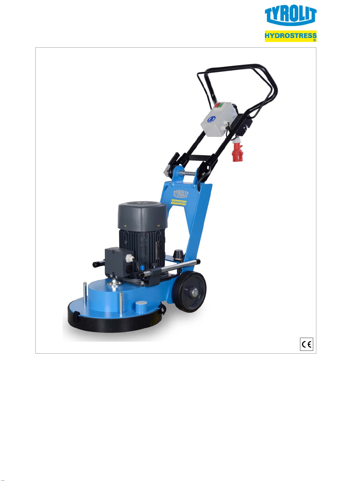
EN Floor grinding machine FGE 400
9
4 Maintenance
Follow the safety instructions in Chapter 2!
The operating and maintenance personnel resp
onsible for the machine must ensure that no one
can enter the machine's danger zone during
operation or maintenance work.
Maintenance work may only be performed by
trained specialists! They must be familiar with
the dangers associated with such work, protect
themselves and avoid danger!
When working on the machine (set-up, mainte
nance, service, repair, cleaning, etc.), the power
supply of the machine has to be disconnected
from the mains
(disconnect the plug) and the drive must be at a
standstill!
Perform cleaning and maintenance work in ac
cordance with the operating manual and check
the safety devices for completeness and functio
nality.
4.1 Customer service and spare parts
In case of customer service queries, replacement
parts or repairs, please contact the manufacturer. To
ensure your queries are dealt with as quickly as pos
sible, always quote your machine data. These are
located on the machine's nameplate.
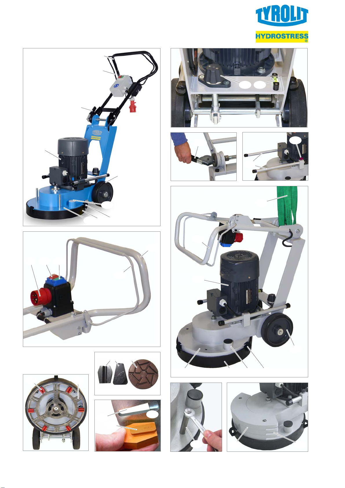
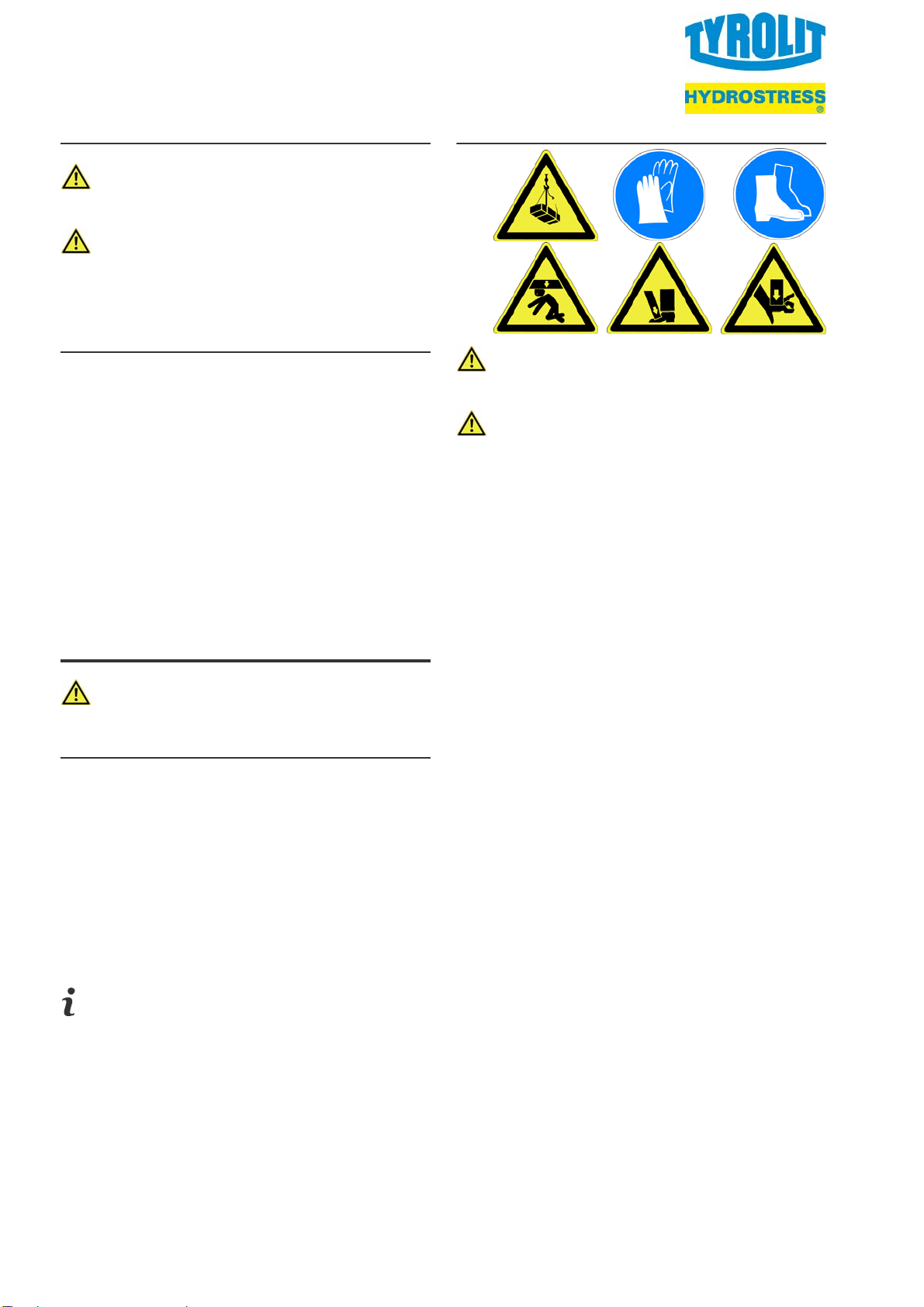
4.2 Attaching/Removing additional weights
Risk of injury from heavy additional weights!
Only grip the additional weights at the recessed
handles [25, Fig. L]! Work with care!
1. Screw 2 bolts [23, Fig. K, spanner size 13] into
the safety hood [7, Fig. J].
2. As needed, grip 1 ... 3 additional weights
[24, Fig. L] and slide these over the bolts.
The removal is carried out in logical reverse
order.
4.3 Tilting the machine
Before tilting the machine, always make sure
that it is on an even, level floor surface!
1. Disconnect the power plug [2, Fig. A] from the
mains.
2. Swivel and lock the guide handle [1, Fig. A] in
the stretched position (!Chapter 3.1).
3. Remove additional weights (!Chapter 4.2).
4. Tip the machine and place it on the floor
(!Fig. C/N/R).
4.4 Mounting and dismantling ETX diamond tools
The consistency of the surface to be ground de
termines the type or composition of the tools to be
used.
All of the ETX diamond tools [!Fig. D] authori
zed for this machine are removed and mounted
in the same manner.
Always mount tools of the same type according
to the processing specifications. The heights of
the diamond tools (degree of wear) must be the
same.
1. Tilt the machine (!Chapter 4.3).
2. Gently tap with a lump hammer to loosen the
tools [13, Fig. E] from the EXT locating
plate [14, Fig. C/E] in the direction of the centre
and then remove.
3. Insert new tools in the ETX holder [17, Fig. E]
and press toward the outer edge of the ETX lo
cating plate (use lump hammer if necessary).
4. Set the machine upright, swivel and lock the
guide handle in standard position
(!Chapter 3.1).
4.5 Cleaning the machine
Do not use high pressure cleaners or com
pressed air to clean the machine!
1. Tilt the machine (!Chapter 4.3).
2. After use, clean the machine and tools with a
dry method such as a vacuum cleaner with a
suitable filter, a cloth or a brush.
3. Set the machine upright, swivel and lock the
guide handle in standard position
(!Chapter 3.1).