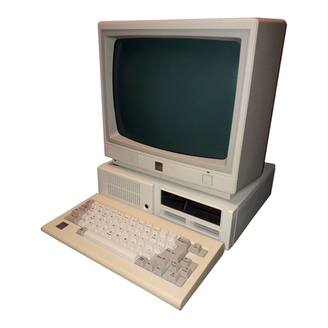
IBM PS/2 80 Owner's manual

FRONT
PICTURE 1
Part Number 84F8548
Form Number S64F-3995-01
September 25, 1990
IBM PS/2 Model 80 HMR
¦ Copyright IBM Corp. 1990
FRONT - 1

EDITION Edition Notice
Safety Information
Refer to the Hardware Maintenance Reference General Information
pamphlet in this manual for the following safety information:
General Safety
Electrical Safety.
Second Edition (September 1990)
The following paragraph does not apply to the United Kingdom or any
country where such provisions are inconsistent with local law:
INTERNATIONAL BUSINESS MACHINES CORPORATION PROVIDES THIS PUBLICATION
"AS IS" WITHOUT WARRANTY OF ANY KIND, EITHER EXPRESS OR IMPLIED,
INCLUDING, BUT NOT LIMITED TO, THE IMPLIED WARRANTIES OF
MERCHANTABILITY OR FITNESS FOR A PARTICULAR PURPOSE. Some states do
not allow disclaimer of express or implied warranties in certain
transactions, therefore, this statement may not apply to you.
This publication could include technical inaccuracies or typographical
errors. Changes are periodically made to the information herein;
these changes will be incorporated in new editions of the publication.
IBM may make improvements and/or changes in the product(s) and/or the
program(s) described in this publication at any time.
It is possible that this publication may contain reference to, or
information about, IBM products (machines and programs), programming,
or services that are not announced in your country. Such references
or information must not be construed to mean that IBM intends to
announce such IBM products, programming, or services in your country.
Requests for technical information about IBM products should be made
to your IBM Authorized Dealer or your IBM Marketing Representative.
IBM may have patents or pending patent applications covering subject
matter in this document. The furnishing of this document does not
give you any license to these patents. You can send license
inquiries, in writing, to the IBM Director of Commercial Relations,
IBM Corporation, Armonk NY 10504.
¦ Copyright International Business Machines Corporation 1990. All
rights reserved.
Note to U.S. Government Users -- Documentation related to restricted
rights -- Use, duplication or disclosure is subject to restrictions
set forth in GSA ADP Schedule Contract with IBM Corp.
IBM PS/2 Model 80 HMR
Edition Notice
¦ Copyright IBM Corp. 1990
EDITION - 1
FRONT_1 Special Notices
References in this publication to IBM products, programs, or services do
not imply that IBM intends to make these available in all countries in
which IBM operates. Any reference to an IBM product, program or service
is not intended to state or imply that only IBM's product, program, or
service may be used. Any functionally equivalent product, program, or
service that does not infringe any of IBM's intellectual property rights
or other legally protectible rights may be used instead of the IBM
product, program, or service. Evaluation and verification of operation in
conjunction with other products, programs, or services, except those
expressly designated by IBM, are the user's responsibility.
IBM may have patents or pending patent applications covering subject
matter in this document. The furnishing of this document does not give
you any license to these patents. You can send license inquiries, in
writing, to the IBM Director of Commercial Relations, IBM Corporation,
Purchase, NY 10577.
The following terms, denoted by an asterisk (*) in this publication, are
trademarks of the IBM Corporation in the United States and/or other
countries:
IBM
Personal System/2
Micro Channel.
IBM PS/2 Model 80 HMR
Special Notices
¦ Copyright IBM Corp. 1990
FRONT_1 - 1

CONTENTS Table of Contents
EDITION Edition Notice
FRONT_1 Special Notices
CONTENTS Table of Contents
1.0 Product Description
1.1 Security
1.1.1 Cover Lock
1.1.2 Power-On Password
1.2 System-Board Features
1.2.1 Microprocessor
1.2.2 CMOS RAM and CMOS RAM Extension
1.2.3 ROM BIOS
1.2.4 VGA
1.2.5 Serial Port
1.2.6 Parallel Port
1.2.7 Diskette-Drive Controller
1.2.8 Keyboard Connector and Pointing-Device Connector
2.0 Option Compatibility
2.1 Drive and Diskette Compatibility
2.2 Fixed Disk Drives
2.3 Terminators
3.0 Operating Requirements
3.1 Power Supply
4.0 Diagnostic Programs
4.1 System Memory
4.1.1 System-Board Memory
4.1.2 Memory-Expansion Adapters
4.1.3 Memory Requirements and Limitations
4.1.4 Memory Errors
5.0 Specifications
6.0 Special Tools
7.0 Service Position
8.0 Removals and Replacements
8.1 1005 Cover
8.2 1010 Cover Lock
8.3 1015 80386 System-Board Memory-Expansion Kit
8.4 1020 Adapters
8.5 1025 80386 Memory Expansion Kit
8.6 1030 Math Coprocessor
8.7 1035 Battery and Speaker Assembly
8.8 1040 Feet
8.9 1045 Front Bezel
8.10 1050 Carrying Handle
8.11 1055 Power Supply
8.12 1060 Diskette Drive
8.13 1065 Diskette-Drive Cable Retainer
8.14 1070 Diskette-Drive Support Structure
8.15 1075 Fixed Disk Drive (Front Bay)
8.16 1080 Fixed Disk Drive (Rear Bay)
8.17 1085 Fixed-Disk-Drive Bracket (SCSI Drives)
8.18 1090 Fixed-Disk-Drive Support Structure (SCSI Drives)
8.19 1095 System Board
8.20 1100 Fixed-Disk-Drive Support-Structure Bracket
9.0 Locations
9.1 Front View
9.2 Rear View
9.3 Interior View
9.4 Internal Cables Model 80 (8580-041, 071, 111, 311)
9.5 Internal Cables Model 80 (8580-081, 121, 161, 321, A21, A31, A16)
9.6 System Board Model 80 (8580-041, 071, 081, 111, 121, 161, 311, 321)
9.7 System Board Model 80 (8580-A21, A31, A16)
10.0 Safety Grounds
IBM PS/2 Model 80 HMR
Table of Contents
¦ Copyright IBM Corp. 1990
CONTENTS - 1

1.0 Product Description
The IBM (*) Personal System/2 (*) Model 80 computers use the IBM Micro
Channel (*) architecture. The features of the various types of Model 80
are:
Security: cover lock and power-on password
System board:
- 16-, 20-, or 25-MHz 80386 Microprocessor.
- 80387 Math Coprocessor connector.
- 1MB, 2MB, or 4MB (MB = 1,048,576 bytes) of random access memory
(RAM). System-board memory can be expanded to 2MB, 4MB, or 8MB
depending on the model. The total system memory capacity is 16MB.
- 64 bytes of complementary metal-oxide semiconductor random access
memory (CMOS RAM).
- Read-only memory basic input/output system (ROM BIOS).
- Video graphics array (VGA).
- Eight expansion slots:
- Three or four 32-bit slots, varies with model
- Four or Five 16-bit slots, varies with model. (One 16-bit
slot with an auxiliary-video connector extension, and one slot
normally occupied by the fixed-disk-drive adapter.)
- Serial port.
- Parallel port.
- Diskette-drive controller.
- Keyboard connector.
- Pointing-device connector.
- Display connector.
- Fixed-disk-drive connector.
Power supply:
- Automatically switches to the 100-125 Vac or the 200-240 Vac range
- 50 or 60 Hz
- 225 or 242 watts.
Battery (to keep CMOS RAM active when power is off)
Speaker
101/102-key keyboard
Fixed disk drives supported (see "Fixed Disk Drives" in topic 2.2).
(*) IBM, Personal System/2, and Micro Channel are trademarks of
the International Business Machines Corporation.
Subtopics
1.1 Security
1.2 System-Board Features
IBM PS/2 Model 80 HMR
Product Description
¦ Copyright IBM Corp. 1990
1.0 - 1

1.1 Security
Subtopics
1.1.1 Cover Lock
1.1.2 Power-On Password
IBM PS/2 Model 80 HMR
Security
¦ Copyright IBM Corp. 1990
1.1 - 1

1.1.1 Cover Lock
The cover lock is on the left side of the system unit and can be unlocked
with the user's key.
If the keys for the cover lock are lost, a new cover-lock assembly can be
ordered (see the parts section in the Hardware Maintenance Service
pamphlet for the system you are servicing). The new assembly contains two
keys. Use one of the new keys, along with a pair of pliers to force the
old cover lock open.
IBM PS/2 Model 80 HMR
Cover Lock
¦ Copyright IBM Corp. 1990
1.1.1 - 1

1.1.2 Power-On Password
A power-on password denies access to the system when the system is
powered-on. To service a system with an active and unknown power-on
password, power-off the system and, do one of the following depending on
which battery and speaker assembly is installed:
If the assembly has pins, short pins 2 and 3 together
If the assembly has no pins, insert a meter lead into connector 1 and
short the other end of the lead to frame ground.
With the assembly shorted, power-on the system. This deactivates the
power-on password. Remove the short after the POST is finished.
To reactivate the power-on password, the user must start the system with
the Reference Diskette in drive A, select the Set features option, and
follow the instructions.
PICTURE 2
IBM PS/2 Model 80 HMR
Power-On Password
¦ Copyright IBM Corp. 1990
1.1.2 - 1

1.2 System-Board Features
The major features of the system board are:
80386 Microprocessor
CMOS RAM
ROM BIOS
VGA
Serial port
Parallel port
Diskette-drive controller
Keyboard connector
Pointing-device connector.
Subtopics
1.2.1 Microprocessor
1.2.2 CMOS RAM and CMOS RAM Extension
1.2.3 ROM BIOS
1.2.4 VGA
1.2.5 Serial Port
1.2.6 Parallel Port
1.2.7 Diskette-Drive Controller
1.2.8 Keyboard Connector and Pointing-Device Connector
IBM PS/2 Model 80 HMR
System-Board Features
¦ Copyright IBM Corp. 1990
1.2 - 1

1.2.1 Microprocessor
The microprocessor interprets and carries out instructions. The 80386
Microprocessor is a 32-bit processor and operates in three modes:
real-address mode, virtual-address (protected) mode, or virtual 8086 mode.
The microprocessor speed is 16 MHz, 20 MHz, or 25 MHz depending on the
model.
IBM PS/2 Model 80 HMR
Microprocessor
¦ Copyright IBM Corp. 1990
1.2.1 - 1

1.2.2 CMOS RAM and CMOS RAM Extension
The CMOS RAM provides 64 bytes of storage. The first 50 bytes are used to
store system-configuration and security information. The real-time clock
uses the remaining 14 bytes to track the date, time, and battery level. A
2KB (KB = 1024 bytes) CMOS RAM extension stores additional configuration
and system-status information.
The data stored in the CMOS RAM and CMOS RAM extension is kept active by
the battery when the system is powered-off. If the stored data is lost
due to a depleted or removed battery, the data can be restored using one
of the following methods:
If the user has a customized configuration that uses settings other
than the default, run the restore configuration program on the user's
backup copy of the Reference Diskette.
If the configuration uses the default settings, run the automatic
configuration program on the Reference Diskette.
IBM PS/2 Model 80 HMR
CMOS RAM and CMOS RAM Extension
¦ Copyright IBM Corp. 1990
1.2.2 - 1

1.2.3 ROM BIOS
ROM BIOS contains the instructions and routines that control the keyboard,
diskette drives, fixed disk drive, displays, and other major input/output
devices in the system. Some adapters have their own ROM modules
containing extended BIOS routines that work with the system-board ROM
BIOS. The routines for performing the power-on self-test (POST) are also
contained in the ROM BIOS.
IBM PS/2 Model 80 HMR
ROM BIOS
¦ Copyright IBM Corp. 1990
1.2.3 - 1

1.2.4 VGA
The VGA is a graphics controller on the system board. The VGA supports
color and monochrome analog direct-drive displays in a variety of modes,
including alphanumeric text mode, and all-points-addressable (APA)
graphics mode.
The VGA supports a maximum of 720-by-400 picture elements (PELs) in the
text mode and 640-by-480 PELs in the graphics mode. The VGA can support
256 colors or 64 shades of gray at one time. Composite video is not
supported.
Model 80 systems can have either one or two 16-bit extended expansion
slots on the system board. These slots extend farther to the rear of the
system board than the others. The extended expansion slots accommodate
video adapters that are designed to interface with the system-board VGA.
Some of these adapters provide a display connector of their own. The
extended expansion slots also support all adapters designed to be
installed in the shorter slots.
Warning: Some non-IBM graphics adapters drive rather than receive VGA
signals. If more than one adapter that drives a VGA signal is installed
in a system, both adapters will be damaged.
IBM PS/2 Model 80 HMR
VGA
¦ Copyright IBM Corp. 1990
1.2.4 - 1

1.2.5 Serial Port
The serial port is fully programmable and supports asynchronous
communications. The 25-pin, D-shell connector provides the signals to
drive a device with a standard 25-contact, RS-232 connector. The
connected device is identified by the system configuration as either
SERIAL 1 or SERIAL 2.
If adapters with serial ports are installed in the system, they can be
configured from SERIAL 1 to SERIAL 8. The port on the system board can be
only SERIAL 1 or SERIAL 2.
Note: Conflicts occur when two or more devices have the same address.
Select the Set configuration option on the Reference Diskette.
Select View configuration to verify that no lines are addressed the
same.
IBM PS/2 Model 80 HMR
Serial Port
¦ Copyright IBM Corp. 1990
1.2.5 - 1

1.2.6 Parallel Port
The parallel port allows the attachment of devices that accept eight bits
of parallel data at standard transistor-transistor-logic (TTL) levels.
The port has a 25-pin, D-shell connector and is designed primarily for
printers. However, the port can be used as an input/output port for any
device or application that matches the input/output capabilities of the
port. When adapters with additional parallel ports are installed, the
system can support three devices, each addressed separately as PARALLEL 1,
PARALLEL 2, or PARALLEL 3.
Note: Conflicts occur when using multiple devices if two or more devices
are addressed the same. Select the Set configuration option on the
Reference Diskette. Select View configuration to verify that no
lines are addressed the same.
IBM PS/2 Model 80 HMR
Parallel Port
¦ Copyright IBM Corp. 1990
1.2.6 - 1

1.2.7 Diskette-Drive Controller
The controller connects to the diskette drives through a single 40-pin
connector on the system board. Signals and voltages are supplied through
the diskette-drive cable that plugs into the connector. These signals and
voltages can operate two IBM 3.5-inch diskette drives.
IBM PS/2 Model 80 HMR
Diskette-Drive Controller
¦ Copyright IBM Corp. 1990
1.2.7 - 1

1.2.8 Keyboard Connector and Pointing-Device Connector
The two 6-pin connectors at the rear of the system board are for a
keyboard and a pointing device (mouse). The keyboard connector is marked
with a small keyboard figure molded into the back panel; the unmarked
connector is for the pointing device. The interface logic is the same for
both.
IBM PS/2 Model 80 HMR
Keyboard Connector and Pointing-Device Connector
¦ Copyright IBM Corp. 1990
1.2.8 - 1

2.0 Option Compatibility
The Model 80 uses only those adapters that are specifically designed for
it. All supported 16-bit adapters operate in any system-board expansion
slot. For supported options, see the parts section in the Hardware
Maintenance Service pamphlet for the system you are servicing.
Subtopics
2.1 Drive and Diskette Compatibility
2.2 Fixed Disk Drives
2.3 Terminators
IBM PS/2 Model 80 HMR
Option Compatibility
¦ Copyright IBM Corp. 1990
2.0 - 1

2.1 Drive and Diskette Compatibility
The following provides information concerning the identification of
diskette drives.
+------------------------------------------------------------------------+
¦ Diskette Drive ¦ Identifying Mark ¦
+------------------------------------+-----------------------------------¦
+------------------------------------+-----------------------------------¦
¦ 3.5 Inch - 720KB ¦ None ¦
+------------------------------------+-----------------------------------¦
¦ 3.5 Inch - 1.44MB ¦ 1.44 on the Eject Button ¦
+------------------------------------+-----------------------------------¦
¦ ¦ ¦
+------------------------------------------------------------------------+
The following addresses the compatibility of diskettes to diskette drives.
+------------------------------------------------------------------------+
¦ Diskette ¦ 720KB ¦ 1.44MB ¦
¦ Capacity ¦ Drive ¦ Drive ¦
+-----------------------+------------------------+-----------------------¦
¦ 1.0MB ¦ Read/Write ¦ Read/Write ¦
+-----------------------+------------------------+-----------------------¦
¦ 2.0MB ¦ Not Compatible ¦ Read/Write ¦
+-----------------------+------------------------+-----------------------¦
¦ ¦ ¦ ¦
+------------------------------------------------------------------------+
Note: For additional information, see "Diskette Drives and Diskettes" in
the IBM Personal System/2 Hardware Maintenance Reference General
Information pamphlet in this manual.
IBM PS/2 Model 80 HMR
Drive and Diskette Compatibility
¦ Copyright IBM Corp. 1990
2.1 - 1

2.2 Fixed Disk Drives
Several fixed disk drives are available for PS/2 systems. The fixed disk
drive and fixed-disk-drive interface must be the same. For example, an
enhanced small device interface (ESDI) adapter must be used with an ESDI
drive. For supported fixed disk drives, see the parts section in the
Hardware Maintenance Service pamphlet for the model you are servicing.
The Model 80 uses fixed disk drives that automatically position the
read/write heads in nondata areas when the system is powered-off. No
special precautions are required regarding parking the heads when moving
the computer.
IBM PS/2 Model 80 HMR
Fixed Disk Drives
¦ Copyright IBM Corp. 1990
2.2 - 1
Table of contents
Other IBM Desktop manuals

IBM
IBM NetVista A22p User manual

IBM
IBM NetVista A21 User manual

IBM
IBM NetVista 6029 Owner's manual

IBM
IBM 6889 - IntelliStation M - Pro User manual

IBM
IBM NetVista A20 User manual

IBM
IBM 6565 - PC 300 PL User manual

IBM
IBM DISA e-collaboration User manual

IBM
IBM NetVista A20 User manual

IBM
IBM IntelliStation M Pro 6230 User manual

IBM
IBM NetVista Troubleshooting guide

IBM
IBM 9234CNU - Lotus Foundations Server User manual

IBM
IBM Z9 Technical manual

IBM
IBM PC 300 User manual

IBM
IBM NetVista X40 User manual

IBM
IBM NetVista A20 Guide

IBM
IBM RT PC User manual

IBM
IBM 2790 User manual

IBM
IBM NetVista A20 User manual

IBM
IBM IntelliStation A Pro User manual

IBM
IBM NetVista X40 User manual