PAGE 4 OF 6 0614 IH-1119
ELECTRONIC INDICATOR
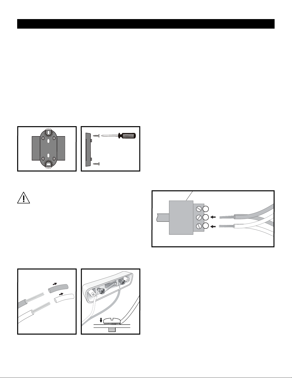
MOUNTING BRACKET TO WALL
1. Determine where to place the Indicator so it is easily
seen by customers.
2. Mark mounting holes on wall using the Indicator Wall
Mount Bracket as a template. (See Figure 6)
3. Drill holes using 5/16" drill bit.
4. Use wall anchors (included) if attaching to surfaces
other than solid wood.
5. Position Wall Mount Bracket over drilled holes and
fasten with two large Phillips screws. (See Figure 7)
WIRING PUSH BUTTONS
WARNING! Electrical Shock Hazard – Do not
connect indicator to power until all push
button and power cord wiring connections are
complete. Serious electrical shock, injury or
death may result.
The Take-A-Number System includes 3 push buttons. Set
two push buttons to advance numbers and one to go
back to a previous number.
1. Cut a length of electrical wire to reach from each
push button location to Indicator.
2. Strip one wire end about 1/2". (See Figure 8)
3. On the underside of one push button: Loosen
screws. Wrap one wire end around one screw post
and wrap the other wire end around the other screw
post. Retighten the screws. (See Figure 9)
4. Secure push buttons to surface using the two
included slotted screws. (Optional)
5. Repeat steps 1–3 with the two remaining push
buttons.
WIRING PUSH BUTTONS TO DATA CONNECTORS
1. Strip wire ends about 1/2" for all three push buttons.
(See Figure 8)
2. Each Data Connector has 3 numbered ports. Loosen
screws on ports 2 and 3 with a mini flat head screwdriver.
3. For (+) push buttons: Twist the same color wires
together from two of the push buttons (copper to
copper, silver to silver). Insert the twisted wires into ports
2 and 3 on one data connector. Tighten screws to
secure wires. (See Figure 10)
4. For (–) push button: Use the wire from one remaining
push button. Insert the wires into ports 2 and 3 on the
second data connector. Tighten screws to secure
wires. (See Figure 10)
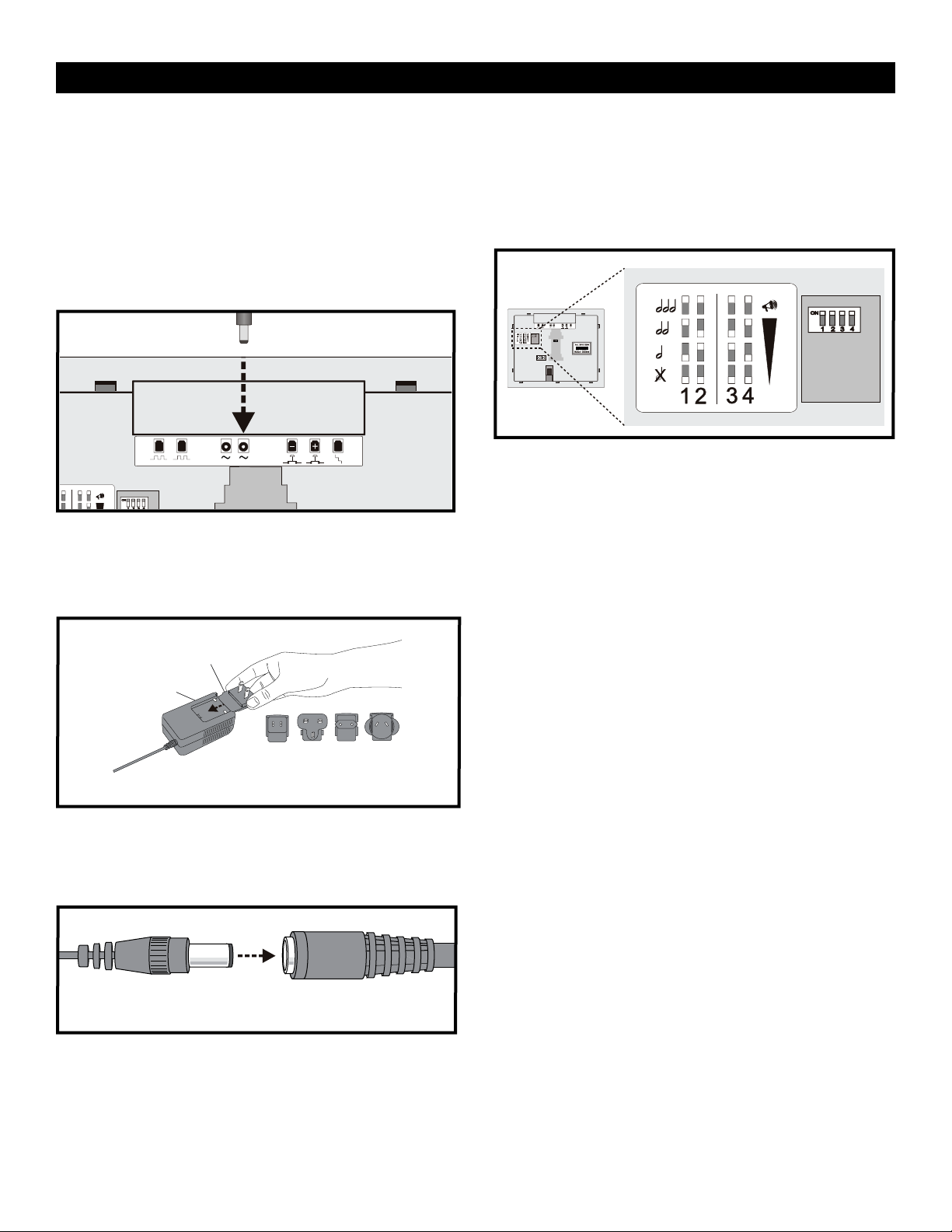
PLUGGING DATA CONNECTORS INTO INDICATOR
1. Plug the data connector with two push buttons
attached into the ‘+’ jack on the back of the
Indicator. (See Figure 11 on next page)
2. Plug the other data connector with the single push
button attached into the ‘–’ jack on the back of the
Indicator. (See Figure 11 on next page)
3. Mark which push button is plugged into the ‘+’ and
‘–’ jacks:
‘+’ Push button advances the numbers.
‘–’ Push button goes back to previous numbers.
INDICATOR - MOUNTING AND INSTALLATION
Figure 6 Figure 7
Figure 8 Figure 9
Figure 10
DATA Connector