manuals.online logo
Brands
  1. Home
  2. •
  3. Brands
  4. •
  5. U-Line
  6. •
  7. Smoke Alarm
  8. •
  9. U-Line H-9470 User manual

U-Line H-9470 User manual

PAGE 1 OF 3 0621 IH-9470
SMOKE DETECTOR,
10-YEAR LITHIUM BATTERY
1-800-295-5510
uline.ca
H-9470
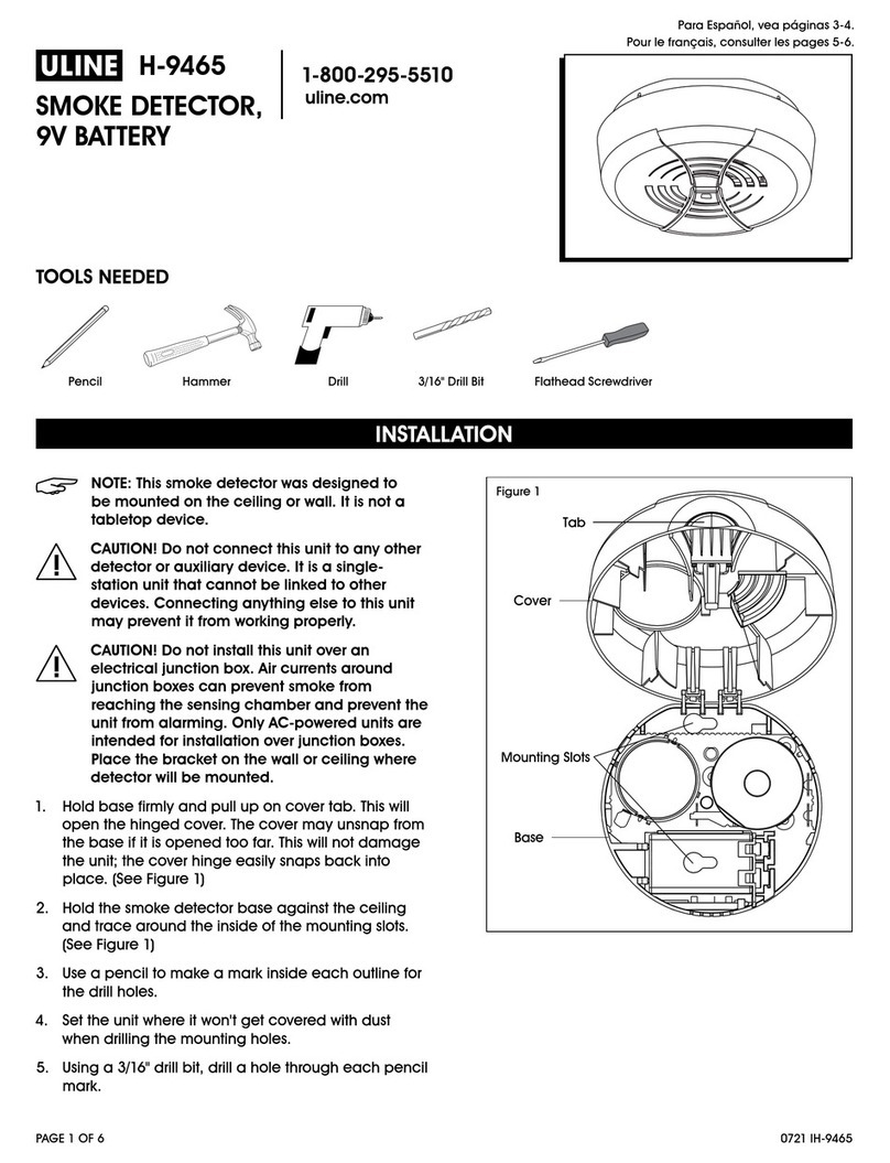
NOTE: This smoke detector was designed to
be mounted on the ceiling or wall. It is not a
tabletop device.
CAUTION! Do not connect this unit to any other
detector or auxiliary device. It is a single-
station unit that cannot be linked to other
devices. Connecting anything else to this unit
may prevent it from working properly.
CAUTION! Do not install this unit over an
electrical junction box. Air currents around
junction boxes can prevent smoke from
reaching the sensing chamber and prevent the
unit from alarming. Only AC-powered units are
intended for installation over junction boxes.
Place the bracket on the wall or ceiling where
detector will be mounted.
1. If locking the smoke detector to the mounting
bracket, please read the "Locking Feature
(Optional)" section.
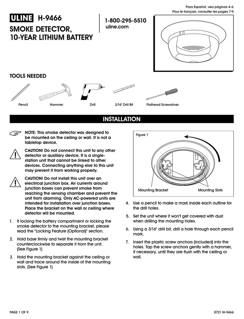
2. Hold base firmly and twist the mounting bracket
counterclockwise to separate it from the unit.
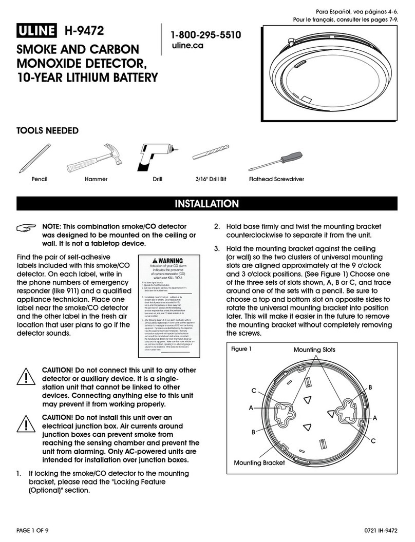
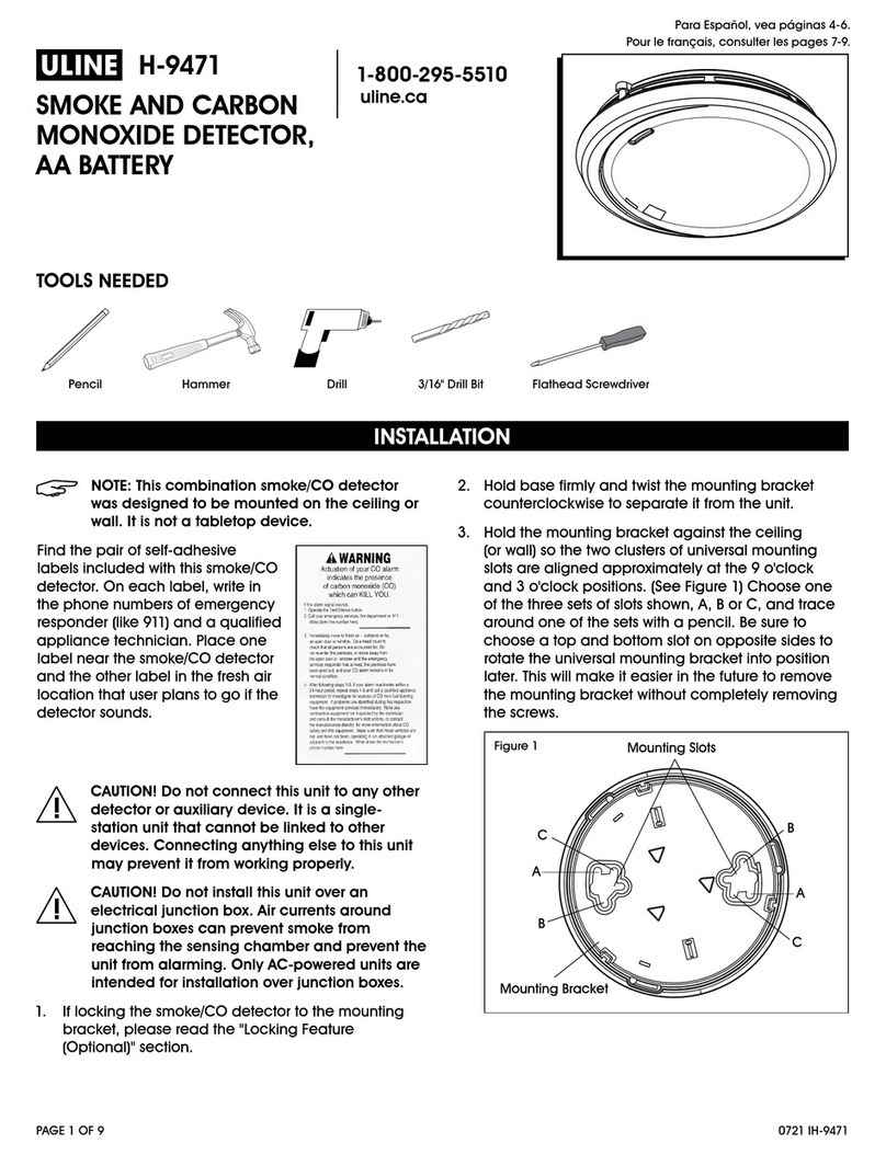
3. Hold the mounting bracket against the ceiling
(or wall) so the two clusters of universal mounting
slots are aligned approximately at the 9 o'clock
and 3 o'clock positions. (See Figure 1) Choose one
of the three sets of slots shown, A, B or C, and trace
around one of the sets with a pencil. Be sure to
choose a top and bottom slot on opposite sides to
rotate the universal mounting bracket into position
later. This will make it easier in the future to remove
the mounting bracket without completely removing
the screws.
Mounting Slots
Mounting Bracket
A
C
B
B
C
A
Figure 1
4. Set the unit where it won't get covered with dust
when drilling the mounting holes.
5. Using a 3/16" drill bit, drill a hole through each pencil
mark.
6. Insert the plastic screw anchors (included) into the
holes. Tap the screw anchors gently with a hammer,
if necessary, until they are flush with the ceiling or
wall.
INSTALLATION
TOOLS NEEDED
Pencil Hammer Drill 3/16" Drill Bit Flathead Screwdriver
PAGE 2 OF 3 0621 IH-9470
INSTALLATION CONTINUED
7. Install the screws but do not tighten completely.
Attach the mounting bracket by aligning the screws
in the open portion of the universal mounting slots
and rotating the bracket into place. (See Figure 2)
Tighten the screws until they are snug to secure the
bracket (D). Do not overtighten.
Mounting
Bracket
Screw
D
Screw
Figure 2
8. Activate the battery. Mount smoke detector to
mounting bracket to activate. Once unit is activated,
it cannot be turned off.
NOTE: After activating the battery, the power
indicator light may flash. (See Figure 3) If the
unit alarms, the light will blink rapidly, and the
horn will repeatedly sound three beeps, pause,
three beeps. Once the smoke detector is on
the bracket, rotate it to adjust the alignment.
9. Press the test button to test the smoke detector.
(See Figure 3)
Power Indicator
Light
Test Button
Figure 3
10. After 10 years of operation or low battery warning,
deactivate the smoke detector. Insert a tool below
edge and break tab. Slide activation switch to
deactivate mode.
IMPORTANT! At end of life or low battery
indication (chirp), unit must be put into
deactivation mode to deactivate remaining
stored energy in battery. Unit will resist
remounting.
LOCKING FEATURE (OPTIONAL)
1. The optional locking feature is designed to prevent
unauthorized removal of the detector. It is not
necessary to activate the lock in single-family
households where unauthorized detector removal is
not a concern.
2. The feature uses a locking pin, which is molded into
the mounting bracket. Remove locking pin by using
needle-nose pliers or a utility knife.
IMPORTANT! To permanently remove the
locking pin, insert a flathead screwdriver
between the locking pin and the lock and pry
the pin out of the lock.
LOCKING THE MOUNTING BRACKET
1. Using needle-nose pliers, detach the locking pin
from the mounting bracket. (See Figure 4)
Locking Pin
Figure 4
2. Insert the locking pin through the hole on the back
of the smoke detector. (See Figure 5)
Locking Pin
Figure 5
3. When attaching the smoke detector to the mounting
bracket, the locking pin's head will fit into a notch
on the bracket.
PAGE 3 OF 3 0621 IH-9470
INSTALLATION CONTINUED
UNLOCKING THE MOUNTING BRACKET
1. Insert a flathead screwdriver between the mounting
bracket and the locking pin. (See Figure 6)
Figure 6
2. Pry the smoke detector away from the bracket by
pushing up the screwdriver and turning the smoke
detector counterclockwise at the same time.
1
-800-295-551
0
uline.ca

Other U-Line Smoke Alarm manuals

U-Line H-9468 User manual

U-Line

U-Line H-9468 User manual

U-Line H-9466 User manual

U-Line

U-Line H-9466 User manual

U-Line H-9471 User manual

U-Line

U-Line H-9471 User manual

U-Line H-9465 User manual

U-Line

U-Line H-9465 User manual

U-Line H-9472 User manual

U-Line

U-Line H-9472 User manual

Popular Smoke Alarm manuals by other brands

SCS DAAF-1Y-CE Installation and use

SCS

SCS DAAF-1Y-CE Installation and use

Disty disty-guard operating instructions

Disty

Disty disty-guard operating instructions

Kidde 1276 user guide

Kidde

Kidde 1276 user guide

LST 2251EIS Specification sheet

LST

LST 2251EIS Specification sheet

resideo 5800CMBOVC Quick installation guide

resideo

resideo 5800CMBOVC Quick installation guide

Ei Electronics Ei146 Optical manual

Ei Electronics

Ei Electronics Ei146 Optical manual

HST HP101U Installation and operation manual

HST

HST HP101U Installation and operation manual

Paradox Matrix2000 user guide

Paradox

Paradox Matrix2000 user guide

LST BEAMLRK Specifications

LST

LST BEAMLRK Specifications

Edwards 562NSTT-OEM-ATT01 user guide

Edwards

Edwards 562NSTT-OEM-ATT01 user guide

Nemaxx M1-Mini Original operating instructions

Nemaxx

Nemaxx M1-Mini Original operating instructions

First Alert 9120 Series user manual

First Alert

First Alert 9120 Series user manual

Masterbuilt MPS250S manual

Masterbuilt

Masterbuilt MPS250S manual

Ei Electronics Ei 151TLR Ionisation product manual

Ei Electronics

Ei Electronics Ei 151TLR Ionisation product manual

Siterwell GS522C user manual

Siterwell

Siterwell GS522C user manual

Bosch FAS-420-TP Series Quick installation guide

Bosch

Bosch FAS-420-TP Series Quick installation guide

Teletek electronics IRIS installation manual

Teletek electronics

Teletek electronics IRIS installation manual

Vesta SD-29-SC-AC Series quick start guide

Vesta

Vesta SD-29-SC-AC Series quick start guide

manuals.online logo
manuals.online logoBrands
  • About & Mission
  • Contact us
  • Privacy Policy
  • Terms and Conditions

Copyright 2025 Manuals.Online. All Rights Reserved.