OPERATION
1 Inspect the machine, hoses, and cleaning tools for cleanliness and completeness.
2 Fill the solution tank with water. Using warm water may be a benefit in cleaning effectiveness, but do not
use hot water (above 130 °F/54 °C) in the tank.
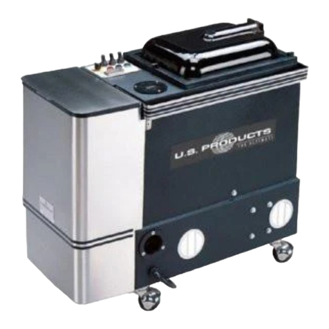
3 Plug in the power cords. Do not connect both cords to the same outlet; the green, circuit locator light (3)
on the switch plate should light up. If the locator light does not come on, try different outlets with one of
the cords until it does. If you are certain the cords are on separate circuits, but the green light still does not
light up, turn on the Bypass switch (1). CAUTION: using the bypass switch when the cords are on the same
circuit may cause the circuit breaker in the wall to trip. NOTE: the receptacle on the left (viewed from behind
the machine) powers the heater. The red light (2) will come on when the heat exchanger is actively heating.
4 Add liquid cleaning solution, with a pH of between 5 and 10, to the solution tank.
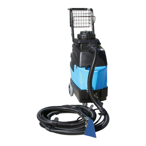
5 Attach the spray hose to the solution quick disconnect and the vacuum hose to the hose barb on the
recovery tank. Pull the hoses off the reel to the desired length. Attach the other ends of the hoses to
the cleaning tool.
6 Allow the heat exchanger two minutes to reach operating temperature.
7 Turn on the pump (6). Turn on the vacuums (4& 5).
8 Begin cleaning using the correct hoses and tool. Spray about three strokes, then stop spraying and do a
vacuum only pass over the are just wetted. Move on to the next area. Spray for only 8-10 seconds on each
spray pass.
9 Use defoamer in the recovery tank any time foaming occurs.
10 Monitor the water level in the solution tank. Do not let the pump run dry.
11 When the solution tank gets low, turn both the pump, and the vacuums off, fill the solution tank, empty
and clean the recovery tank.
12 When finished with the job, remove any unused solution from the solution tank, and run a few
gallons of clean water through the system. Drain the recovery tank by placing the dump hose into
a bucket or drain, and then remove the cap.
DUAL CORD SENSOR CIRCUIT:
This unique, patented system is operated by a solid state circuit. It will inform the operator when the two cords
are plugged into separate circuits by turning on the green, circuit locator light. This helps to prevent tripping
circuit breakers. NOTE: if the circuit locator light does not illuminate when the cords are plugged in, then both
cords are on the same circuit. Try other outlets with one of the cords until you get the locator light to come on.
NOTE: if the bypass, or heat, switch is turned on when both cords are on the same circuit, the breaker may trip.
BYPASS SWITCH:
The bypass switch completely bypasses the circuit locator. Use this feature when you cannot get the green light to
come on and you believe that the two cords are on separate circuits.
CAUTION: If the bypass switch is on and the two cords are plugged into the same circuit, the breaker may blow.
BALL FLOAT VACUUM SHUT-OFF:
Prior to using the machine, always check that the float filter is clean and the ball can travel freely. When the
recovery tank is full, the ball float will rise and will shut off the vacuum flow to prevent any more water from
entering the tank. When this occurs, turn off the vacuum and empty the recovery tank.
NOTE: if foam is present, or if the ball float is prevented from rising, the float will not be able to stop the air flow,
CAUTION: Use care when handling hazardous chemicals.
CAUTION: Never leave the machine running when you are not actively using it.
CAUTION:
Always use a defoamer when foaming occurs to prevent vacuum
motor damage.
DANGER: Do NOT use solvents, or any chemicals that may be flammable, explosive
or combustible.
4
