Solar Charge Controller 6830-122-C10/15/20
2013-06-25 2 Version 6
2 General Information
2.1 Product Overview
Thank you for selecting U-Tron LS series solar light controller that a opts
the most a vance igital technique an operates fully automatically. The
Pulse Wi th Mo ulation (PWM) battery charging can greatly increase the
lifetime of battery. It has various unique functions an quite easy to use, such
as:
•12/24V automatic recognition
•High efficient Series PWM charging, increase the battery lifetime an
improve the solar system performance.
•Use MOSFET as electronic switch, without any mechanical switch
•Wi ely use , automatically recognize ay/night.
•Digital LED menu, only one key solve all setting simply
•Intelligent timer function with 1-15 hours option
• Unique ual timer function, enhance the flexibility of street light system.
• Gel, Seale an Floo e battery type option.
•A opt temperature compensation, correct the charging an ischarging
parameters automatically an improve the battery lifetime.
•Electronic protection: Overheating, over charging, over ischarging,
overloa , an short circuit.
•Reverse protection: any combination of solar mo ule an battery.
The controller is for off-gri solar system, especially in solar light system,
an protects the battery from being over charge by the solar mo ule an
over ischarge by the loa s. The charging process has been optimize for
long battery life an improve system performance. The comprehensive
self- iagnostics an electronic protection functions can prevent amage from
installation mistakes or system faults.
Though the controller is easy to operate an use, please take your time to
rea this manual an become familiar with it. This will help you make full
use of all the functions an improve your solar PV system.
Solar Charge Controller 6830-122-C10/15/20
2013-06-25 3 Version 6
2.2 Product Features
Figure 2-1 Lan Star characteristics
1 –Temperature Sensor
Measure ambient temperature an make temperature compensation for
charging an ischarging.
2
–
Charging status LED in icator
An LED in icator that shows charging status an also in icates when battery
voltage is higher than over voltage isconnec
t v
oltage.
3 – Battery status LED in icator
An LED in icator that shows battery status
4 – Battery type setting in icator
The in icator will be on when select battery type.
5 – Timer 2 setting in icator
The in icator will be on when set timer 2.
6 – Timer 1 setting in icator
The in icator will be on when set timer 1.
7 –LED igital isplay
Display the loa work mo e an status
8 –Setting button
Solar Charge Controller 6830-122-C10/15/20
2013-06-25 Version 6
Se
t l
oa work mo e an select battery type (in manual mo e use for loa
ON/OFF).
9 –Solar Mo ule Terminals
Connect solar mo ules.
10 –Battery Terminals
Connect batteries.
11 –Loa Terminals
Connect loa s.
3 Installation Instructions
3.1 General Installation Notes
•Rea through the entire installation section first before beginning installation.
•Be very careful when working with batteries. Wear eye protection. Have
fresh water available to wash an clean any contact with battery aci .
•Uses insulate tools an avoi placing metal objects near the batteries.
•Explosive battery gasses may be present uring charging. Be certain there
is sufficient ventilation to release the gasses.
•Avoi irect sunlight an o not install in locations where water can enter
the controller.
•Loose power connections an /or corro e wires may result in resistive
connections that melt wire insulation, burn surroun ing materials, or even
cause fire. Ensure tight connections an use cable clamps to secure cables
an prevent them from swaying in mobile applications.
•Use with Gel, Seale or Floo e batteries only.
•Battery connection may be wire to one battery or a bank of batteries. The
following instructions refer to a singular battery, but it is implie that the
battery connection can be ma e to either one battery or a group of
batteries in a battery bank.
• Select the system cables accor ing to 3A/mm2 current ensity
Solar Charge Controller 6830-122-C10/15/20
2013-06-25 1 Version 6
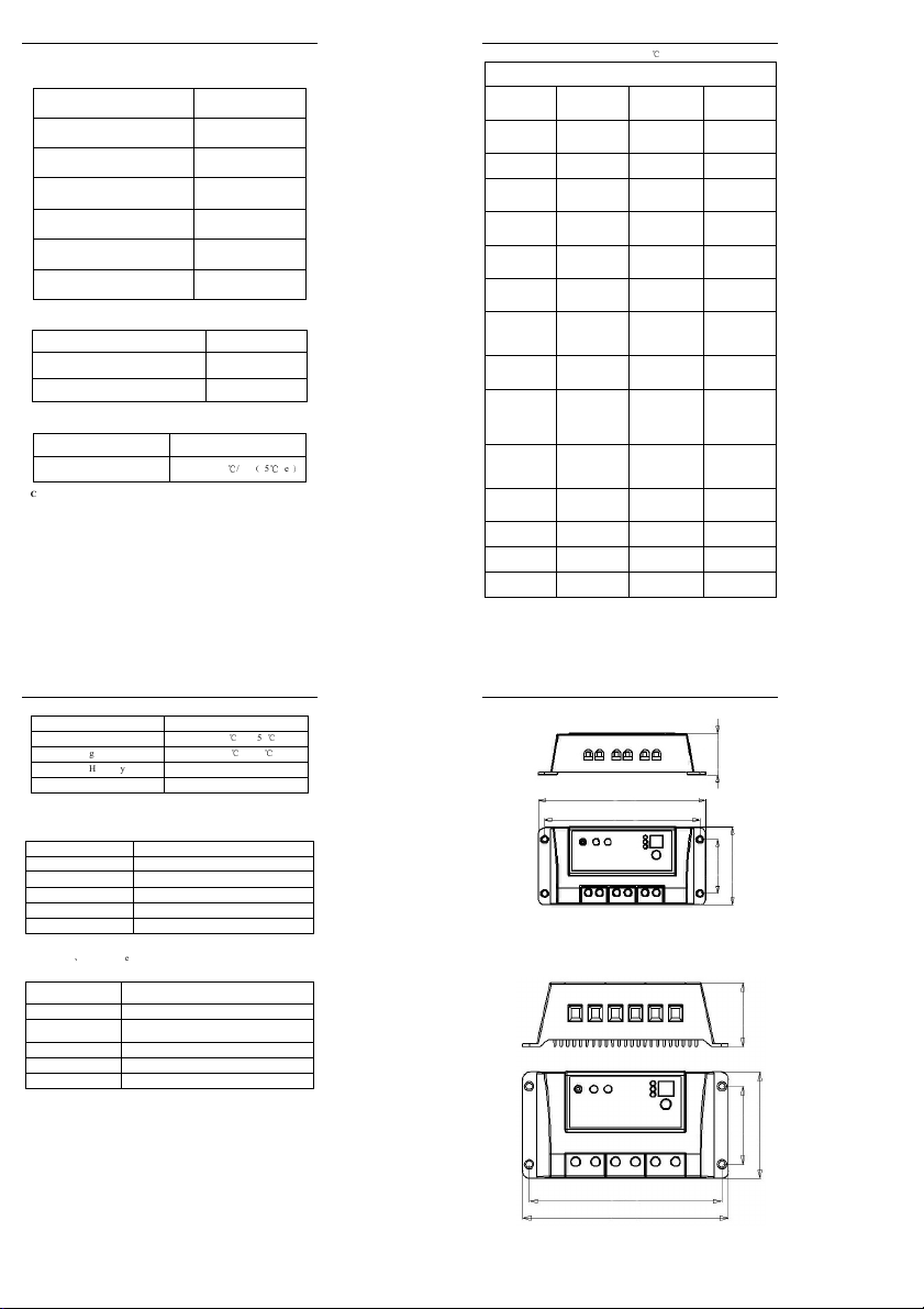
3.2 Mounting
NOTE: When mounting the controller, ensure free air
through the controller heat sink fins. There should be at
least 6 inches (150 mm) of clearance above and below the
controller to allow for cooling. If mounted in an
enclosure, ventilation is highly recommended.
WARNING: Risk of explosion! Never install the
controller in a sealed enclose with flooded batteries! Do
not install in a confined area where battery gassed can
accumulate.
Step 1: Choose Mounting Location
Locate the controller on a vertical surface protecte from irect sun, high
temperature, an water. An make sure goo ventilation.
Step 2: Check for clearance
Place the controller in the location where it will be mounte . Verify that
there is sufficient room to run wires an that there is sufficient room above
an below the controller for air flow.
Figure 3-1 Mounting an cooling
Warm air
Cool air
150mm(5.9inches)
150mm(5.9inches)