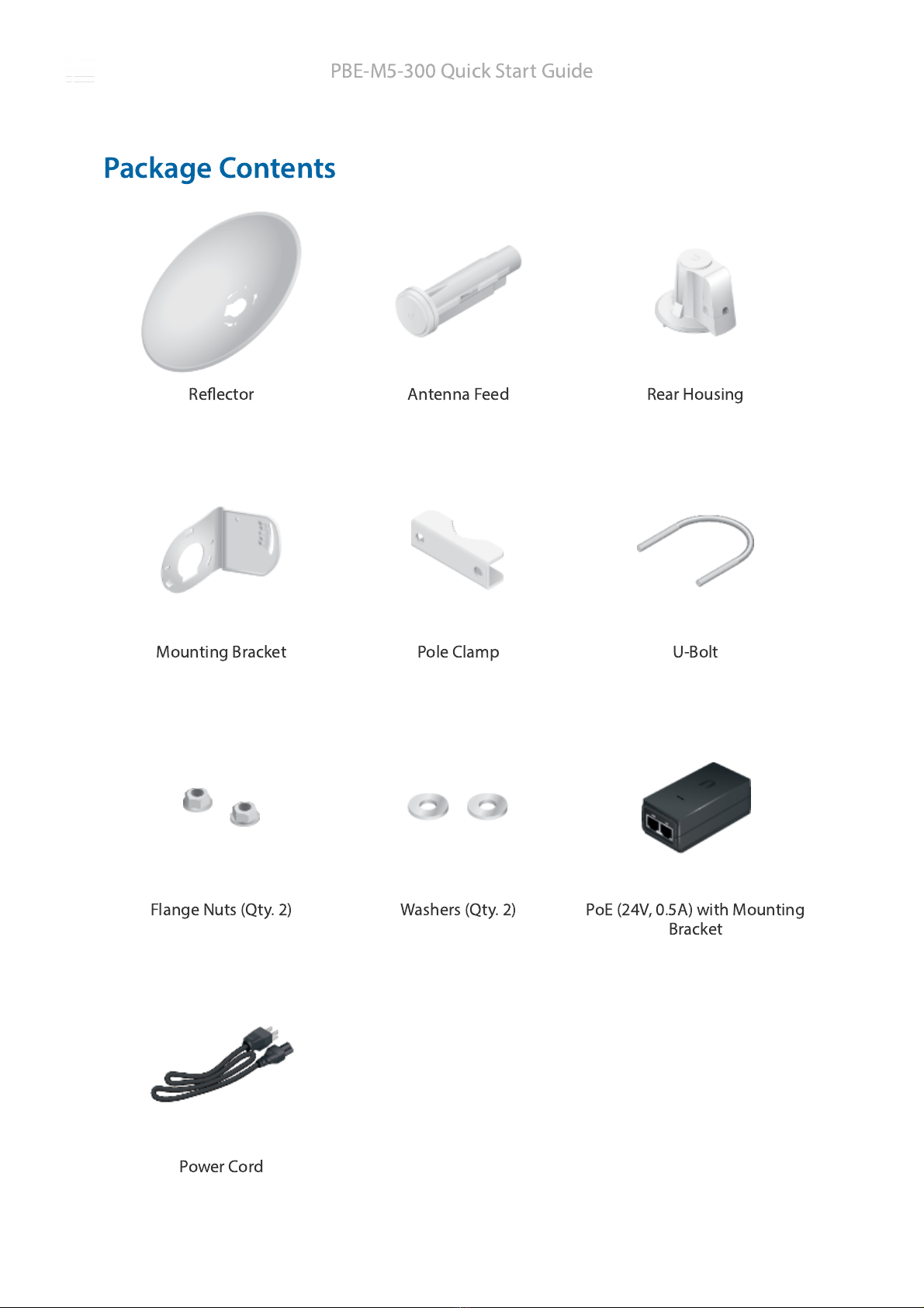
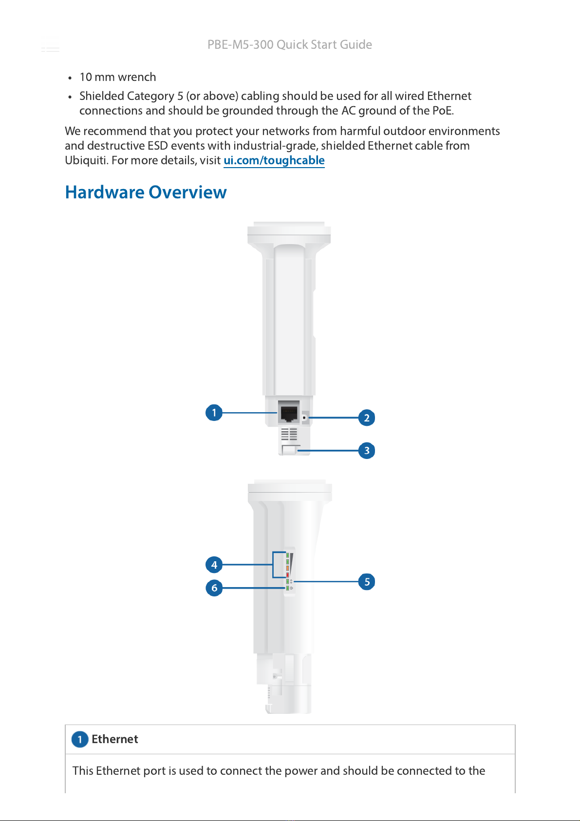
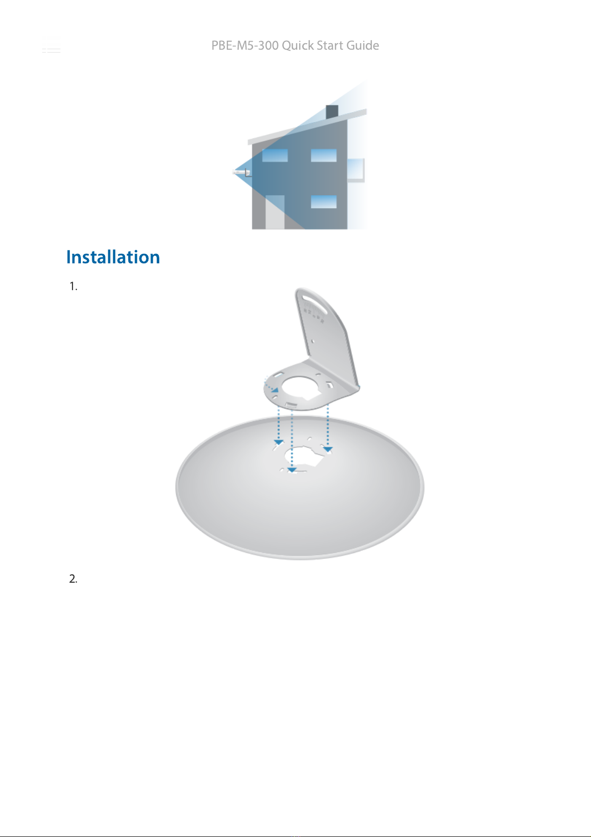
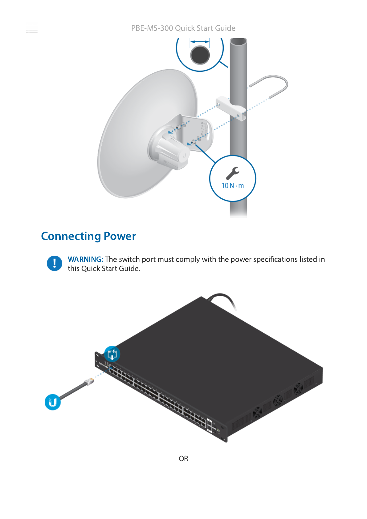
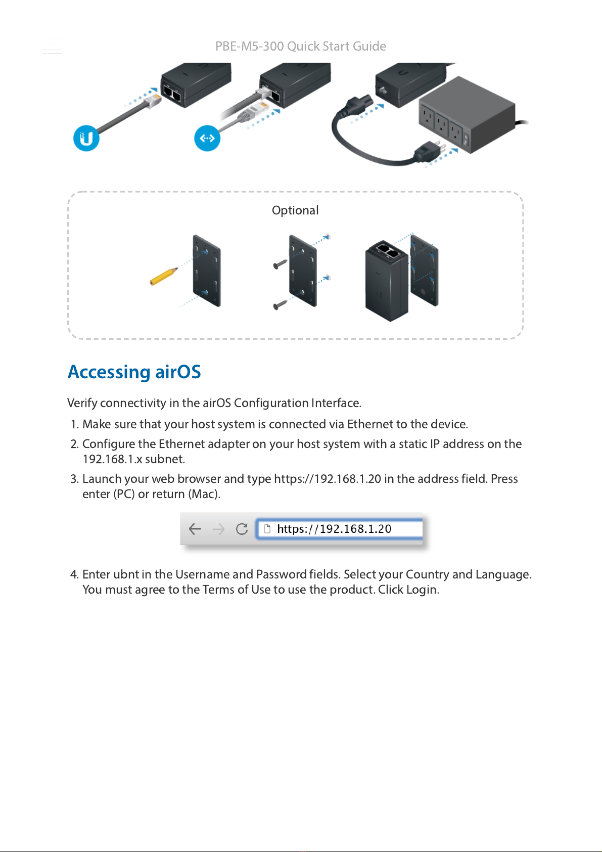
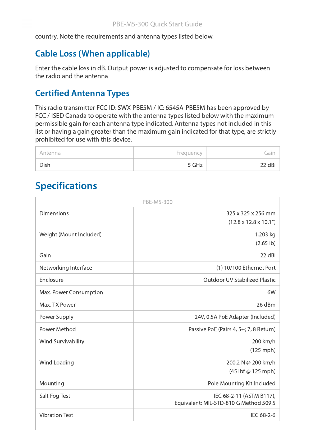
Ubiquiti airMAX PowerBeam PBE-M5-300 User manual
Other Ubiquiti Antenna manuals

Ubiquiti
Ubiquiti AM-5AC22-45 User manual

Ubiquiti
Ubiquiti RocketDish 5G30 User manual

Ubiquiti
Ubiquiti RocketDish LW RD-5G30-LW User manual

Ubiquiti
Ubiquiti RocketDish RD-2G24 User manual

Ubiquiti
Ubiquiti AF-11G35 User manual

Ubiquiti
Ubiquiti AMO-3G12 User manual

Ubiquiti
Ubiquiti AP-5AC-90-HD Air Prism User manual

Ubiquiti
Ubiquiti airMAX Sector AM-9M13 User manual

Ubiquiti
Ubiquiti PS-5AC User manual

Ubiquiti
Ubiquiti airMAX AM-5G20-90 User manual

Ubiquiti
Ubiquiti UniFi UAP-AC-M User manual

Ubiquiti
Ubiquiti airMAX Omni AMO-5G10 User manual

Ubiquiti
Ubiquiti airMAX Sector AM-2G16-90 User manual

Ubiquiti
Ubiquiti PrismStation AC User manual

Ubiquiti
Ubiquiti airMAX Titanium Sector User manual

Ubiquiti
Ubiquiti airMAX Omni AMO-2G10 User manual

Ubiquiti
Ubiquiti RocketDish RD-5G31-AC User manual

Ubiquiti
Ubiquiti AG-HP-5G27 User manual

Ubiquiti
Ubiquiti Horn-5-45 User manual

Ubiquiti
Ubiquiti AM-V2G-Ti User manual


Popular Antenna manuals by other brands

DAVIS
DAVIS Windex AV 3160 installation instructions

Belden
Belden Hirschmann BAT-ANT-N-14G-IP23 Mounting instruction

Vtronix
Vtronix YHK Fitting instructions

KVH Industries
KVH Industries TracVision 6 Technical manual

Leica Geosystems
Leica Geosystems GS10 user manual

Sirio Antenne
Sirio Antenne Gain-Master manual


Feig Electronic
Feig Electronic ID ISC.ANTH200/200 Series manual

TERK Technologies
TERK Technologies TV44 owner's manual

TERK Technologies
TERK Technologies SIR3 owner's manual

Directive Systems & Engineering
Directive Systems & Engineering DSE2324LYRMK quick start guide

HP
HP J8999A instructions

MobilSat
MobilSat MSP-S Mounting instructions