Ubiquiti UniFi UAS-XG User manual

10G Rack-Mountable
Application Server
Model: UAS-XG

Introduction
Thank you for purchasing the Ubiquiti® UniFi® Application
Server. This Quick Start Guide is designed to guide you
through installation and also includes warrantyterms.
Package Contents
UniFi Application Server
Rack-Mount Brackets
(Qty. 2)
Bracket Screws
(Qty. 8)
Mounting Screws
(Qty. 4)
10GRack-Mountable
ApplicationServer
Model:UAS-XG
Cage Nuts
(Qty. 4)
Power Cord U Logo Stickers
(Qty. 2)
Quick Start Guide
System Requirement
Web Browser: Google Chrome (Other browsers may have
limited functionality.)

Network Topology Example
The UniFi Server requires a DHCP-enabled network to obtain
an IP address. Here is a sample network diagram using
thesedevices:
• UAS-XG The UniFi Application Server hosts the UniFi
Network Controller and UniFi Video software applications.
• US-16-XG Connect the 10G Ethernet ports from the
UAS-XG to the US-16-XG or other 10G-capable switches for
maximum throughput. Note that the UAS-XG’s Ethernet
ports are backwards-compatible with standard 1G ports if
10G is not available.
• USG-PRO-4 The UniFi Security Gateway Pro acts as the
DHCP server and connects to the internet.
US-16-XG
USG-PRO-4
Internet
LAN
UAS-XG
WAN

Hardware Overview
Back Panel Ports
LAN1-2
Power USB1-2 VGA
IPMI LAN
Port Description
Power Connect the included Power Cord to the Power
port.
IPMI LAN
(Optional) The dedicated RJ45 port supports
IPMI (Intelligent Platform Management
Interface) for monitoring and control.
USB1-2 (Optional) Connect USB 3.0 devices. Maximum
power per port is 5W (5V, 1A).
LAN1-2 RJ45 ports support 1/10 Gbps Ethernet
connections.
VGA (Optional) Connect a monitor for console access.

Back Panel LEDs
LAN2
Activity
LAN2
Speed
IPMI
Link
IPMI
Activity
LAN1
Activity
LAN1
Speed
IPMI LAN LEDs
LED State Status
Link
Off No Link
Amber Link Established
Activity
Off No Activity
Red Activity
LAN1/2 LEDs
LED State Status
Activity
Off No Link
Amber Flashing Indicates Activity
Speed
Off No Connection or
Link Established at 10/100Mbps
Amber Link Established at 1 Gbps
Green Link Established at 10Gbps

Front Panel LEDs
HDD1/2
LAN1/2
System
System LED
Color State Status
White Flashing Initializing
Blue Steady Functioning Properly
LAN1/2 LEDs
Color State Status
Green
Steady Link Established at 1/10 Gbps
Flashing Indicates Activity
HDD1/2 LEDs
Color State Status
Green Flashing Indicates Read/Write Activity
Amber Steady Indicates HDD Error

Front Panel Ports
USB3/4
USB3-4 (Optional) Connect USB 2.0 devices. Maximum power
per port is 5W (5V, 1A).
Front Panel Buttons
ResetPower
Button Description
Power Press to turn the UniFi Server on or off.
Reset
The UniFiServer should be running after bootup
is complete, and the System LED is blue. Press
the Reset button for a softreboot.

Front Panel HDD Bays
One 8 TB HDD is pre-installed. If you want to replace the HDD,
follow these instructions:
1. Before replacing the HDD, ensure that the UniFi Server is
powered off to prevent any software disruption.
2. To replace the HDD, press the HDD bay door.
3. Once the door is released, rotate the door and pull the
HDD bay out.
4. Replace the pre-installed HDD with another HDD (optional)
and then close the HDD bay door.

Before You Begin
Remove the labels that secure the HDD bay doors.
1. Before removing the labels, ensure that the UniFi Server is
powered off to avoid disconnecting the hard drives while
the UniFi Server is powered on.
2. Pull the white part of the label.
3. Press the HDD bay door.
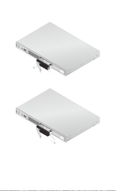
4. Once the door is released, rotate the door and pull the
HDD bay out.
5. Remove the rest of the label.
6. Push the HDD bay back in and close the HDD bay door.
7. Repeat steps 2-6 for the other label.

Hardware Installation
The UniFiServer can be placed on a horizontal surface,
mounted on a wall, or mounted in a rack.
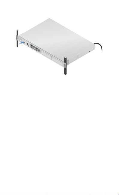
Mounting in a Rack (Optional)
1. Attach the Rack-Mount Brackets to the UniFiServer using
the eight Bracket Screws.
2. Attach the UniFiServer to the rack using the four Mounting
Screws. (If the rack has square slots, then use the Cage Nuts
with the Mounting Screws.)

Connecting Power
1. Connect the Power Cord to the Power port of the
UniFiServer.
2. Connect the other end of the Power Cord to a UPS
(Uninterruptible Power Supply) to prevent possible data
loss from power outages.
USB1
USB2
USB3
USB4
3. Press the Power button to turn on the UniFi Server.
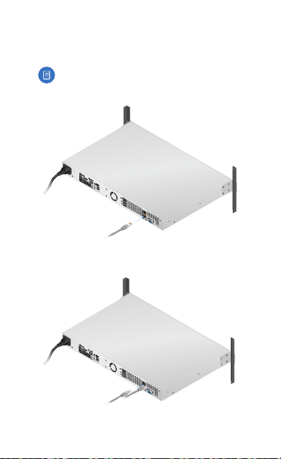
Connecting Ethernet
1. Connect an Ethernet cable from your switch to the LAN1
port of the UniFiServer.
Note: We recommend connecting to the bottom
port, LAN1, if you are only connecting a single
Ethernetcable.
2. For an aggregate link, connect another Ethernet cable from
your switch to the top port, LAN2, of the UniFiServer.
*640-00281-07*
640-00281-07

Connecting VGA
The VGA port is only used for console access in conjunction
with a USB keyboard; it does not need to be connected for
normal operation of the UniFi Server.
1. (Optional) Connect a VGA cable (not included) from your
monitor to the VGA port of the UniFiServer.
Initial Setup via Bluetooth
Use the UniFi Network app to configure the UniFi Server.
1. Download the UniFi Network app from the AppStore®
(iOS) or Google Play™(Android).
2. Enable Bluetooth on your mobile device.
3. Launch the app and hold your mobile device within 1.5m
(5') of the UniFi Server.

4. Tap Add Controller.
5. When the UniFi Server has been discovered, tap Set up
this controller.

6. Configure the following settings:
• Use SSO Credentials Toggle On.
Note: To manually configure the credentials, tap
See credentials in detail and go to step 7.
• Email Enter your email address.
• Username Enter the username for your UBNT Single
Sign-On (SSO) account.
• Password Enter the password for your UBNT SSO
account.
• Retype Password Confirm your password.
Note: The password configured in this step will
also be used for SSH and IPMI access.
• Country Select the appropriate country.
• Time Zone Select the appropriate time zone.
Tap Set Up and go to step 8.

7. Configure the UniFi Controller, UniFi Video NVR, SSH,
and/or IPMI credentials as needed:
• Username Enter the appropriate username.
Note: For the SSH and IPMI credentials, the
username is always ubnt and cannot be changed.
• Password Enter the appropriate password. Tap the
icon to display the password in plaintext.
Note: For the IPMI credential, the password can be
19 bytes (or standard ASCII characters) maximum.
Tap Done.

8. You will be notified when the settings have been saved.
Tap Done.
The username and password you configure in the UniFi
Network app will be used for the pre-installed UniFi Network
Controller and UniFi Video software.

UniFi Software
The UniFi Network Controller and UniFi Video software
applications are pre-installed on the UniFi Server. Follow these
instructions to launch either software:
1. Ensure that your host system is on the same Layer-2
network as the UniFi Server.
2. The UniFi Server is set to DHCP by default, so it will try to
automatically obtain an IP address. Assign a specific IP
address to the UniFi Server, or check the DHCP server for
its IP address.
3. Launch the web browser. In the address field, type https://
followed by the appropriate IP address and port number:
• UniFi Network Controller Enter 8443 as the port
number.
https://<IP_address>:8443
• UniFi Video Enter 7443 as the port number.
https://<IP_address>:7443
4. Press enter (PC) or return (Mac).
Follow the on-screen
instructions.
For information on configuring and using the UniFi Network
Controller or UniFi Video software, refer to the appropriate
User Guide on the website:
• www.ubnt.com/download/unifi
• www.ubnt.com/download/unifivideo
Table of contents
Other Ubiquiti Server manuals


