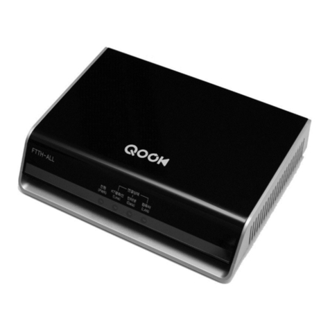
ubiquoss C524W User manual

1
PON ONT
GE-PON ONT
524W
Installation Guide
524W
Installation Guide
C
ubiQuoss Inc.
24F Millennium B/D, 467-12 Dogok-Dong
Gangnam-Gu, Seoul 135-700 Korea
TEL: +82-70-8666-5000
FAX: +82-2-2190-3201
E-mail: oversea.team@ubiQuoss.com

2
PON ONT
Overview
chnology for
45) ports, 2 FXS (RJ
2.11 b/g/n) interface to the subscriber. It is connected to
GE-PON OLT (Optical Line Terminal) and RN (Remote Node) via a fiber optic cable
C524W is connected to the IP terminal devices such as a subscriber’s home-
ides internet service,
subscriber.
f 1.25Gbps with one optic
s the state-of-the-art E-PON
524W supports various
functions, superior to those of the existing Ethernet switch, including QoS
(Quality of Service) function, management function that enables prompt actions
system and a subscriber line, security
ation safely, and subscriber management
crackers.
Key Features
2 FXS Telephone Line(RJ-11) Interface for VoIP service
Supports WEP 64-bit / 128-bit Security password authentication and WPA, WPA2.
Powerful internet sharing function
Supports IEEE 802.1q VLAN Configuration function.
4 Ethernet LAN ports supported 10/100Mbps and one 1.25G EPON port for WAN
Supports ProDHCP function (Server/Client).
Supports specific application, virtual server, DMZ, Access Control and Firewall.
The management program based on WEB and GUI
Remote system management via Internet and software upgrade
The C524W is an ONT (Optical Network Terminal) based on EPON te
home and small office. It supports 4 Fast Ethernet (UTP, RJ
11) ports, and Wi-Fi (80
to provide internet and voice service.
gateway, PC, laptops, smart phones or VoIP phone. It prov
VoIP, and Wi-Fi service at the speed of up to 300 Mbps per
C524W allows up to 32 subscribers to share the data o
cable via passive optical distribution device. It adopt
technology.
By adopting the state-of-the-art E-PON technology, C
to be taken against the problems in the
function that secures subscriber inform
function that secures user information from illegal users such as
Supports IEEE 802.11b/g/n standard.

3
PON ONT
Contents of the Package
Precautions
Warning
Be ant safety information
yofore y u install the C5o 24W, read this section. This section contains import
u should know before working with the system.
Power Co
l when connecting the system to the supply circuit so that wiring is
t overloaded. g,
r better safety. If these materials touch the power
ut.
ible danger in the workshop. Wet floor,
or ungrounded) floor
Servicing the System
ld be turned OFF and
disconnect all power and external cables. items that could get
caught in the system or heat up and cause serious burns.
Do not work alone under potentially hazardous conditions.
Do not perform any action that creates a potential hazard to people or makes
the equipment unsafe.
Disconnecting Power
When disconnecting power, note the following guidelines.
Locate the emergency power-off switch for the room before working with the
system.
To completely turn off the system, disconnect the power connection to all
nsiderations
Be carefu
no
When plugging in a power socket or handling any power source, avoid rin
necklace, metal watch fo
socket or ground of the product, the parts can be burnt o
Always make sure if there is any poss
ungrounded extension, rubbed-off power code, or unsafe (
might be dangerous.
Installing and
Before installation, the power switch of the system shou
Remove all jewelry (including rings and chains) or other
C524W Power Adaptor User Guide
RJ45 Cable

4
PON ONT
the panel board that
off position, and tape
n.
wer supply when the power cord is connected. Line
voltages are present within the power supply even when the power switch is
.
Connecting Cables
When you connect cables, note the following guidelines.
Do not work on the system or connect or disconnect cables during periods of
Working with Lasers
ing guidelines.
To avoid exposure to radiation, do not stare into the aperture of a fiber-optic
ep unused fiber-optic ports capped with a clean dust cap.
Preventing EMI lectromagnetic field,
electro magnetic interference (EMI) can occur between the field and the
signals on the wires. ce (RFI).
ecially when it is caused by lightning or radio transmitters, can
destroy the signal drivers and receivers in the system, and can even create an
electrical hazard by conducting power surges through lines and into the system.
If Strong EMI occurs in the installation place, consult RFI experts to get rid of it.
Disposing of the System
Dispose of the system and its components (including batteries) as specified by all
national laws and regulations.
power supplies.
For DC power supplies, locate the circuit breaker on
services the DC circuit, switch the circuit breaker to the
the switch handle of the circuit breaker in the off positio
Do not touch the po
off and the power cord is connected
lightning activity.
If your system includes a fiber-optic port, note the follow
port. Invisible radiation might be emitted from the aperture of the port when
no fiber cable is connected.
Always ke
When you run wires for any significant distance in an e
Bad plant wiring can result in radio frequency interferen
Strong EMI, esp

5
PON ONT
Installation
Wa ningr
Invisible laser radiation may be emitted from disconnected fibers or connectors. Do not stare into
beams or view directly with optical instruments.
tor on the side of a yellow single-mode optical fiber
optical outlet and the other connector into the PON
und.
2. Connect C524W and PC with Ethernet cable.
3. Connect C524W and Phone with RJ11 cable.
4. Connect the rated power adaptor (12V 1.5A) provided together with C524W main
body.
5. Turn on the power switch.
6. Make su that the POWER LED is ON.
7. Make sure that LAN LED is ON.
1. Connect the SC/APC connec
into the optical terminal of the
port of C524W by pushing them until you hear a clicking so
re
PON Splitter
1
2
3
4

6
PON ONT
nutes. If PON LED is
nal is very low, so please contact the carrier.
DATA LED blink while
see the applicable
wireless device (Wireless) LED blink while data is sent or received.
11. If you set the connection of phone connector exactly, the user can see the TEL
LED comes to light while voice data is sent or received.
8. Make sure that the PON LED is ON in several seconds or mi
red, the optical sig
9. If everything is installed properly, the user can see the
Internet data is sent / received.
10. If you set the wireless configuration properly, the user can

7
PON ONT
Architecture
Front Panel
System
LED
Name Color Status Function Actions to take
ON Power ON Normal Operation
POWER UE OF
eck Power switch at the back
Power adapter & power outlet
BL F Power OFF
Ch
panel->
ON Link (Normal) Normal OperationUp
BLUE BLI n. Optic signal Call Service Provider
NK
(Every 1 sec) Link Dow ON
RED ON Call Service ProviderOptical signal has been lost
PON
PURPLE ON Link Up but optical signal is very low Call Service Provider
OFF No Data transmitting/receiving Call Service Provider
DATA BLUE BLINK Transmitting/receiving Data Normal Operation
ON Ethernet Link Up Normal Operation
BLINK Transmitting/Receiving Ethernet data Normal Operation
LAN 1~4 BLUE
OFF Ethernet Link Down Check cable at PCs
ON Wireless Link Up Normal OperationWireless BLUE
BLINK Transmitting/Receiving Wireless data Normal Operation

8
PON ONT
OFF Wireless Link Down CALL Service Provider
ONormal OperationN TEL Link Up
BLI smitting/Receiving vo ationNK Tran ice data Normal Oper
TEL 1,2 BLUE
OFF TEL Link Down CALL Service Provider
Rear Panel
Indication Description
PON Interface 1.25G PON Port
WPS Wi-Fi Protect Setup
RESET Resets the system to factory default.
LAN 1~4 Fast Ethernet Ports
TEL 1~2 VoIP Ports
ON/OFF Power Switch
12.0V 1.5 A Power Terminal

9
PON ONT
Troubleshooting:
S
is turned on. Once you turn on the power, the POWER
If the POWER LED is
power inlet of
N. If the problem
ase call Service Provider.
ce the optic fiber is
he front panel of C524W should be turned on
r to check the
erly. Once the LAN cable is
elect “set to ‘Obtain IP
automatically’.
Symptom: Al
or My Network Places icon in your desktop.
Step 2 Right-click the Network Neighborhood/My Network Places icon. A drop-down
e bottom of the menu.
Local Area Connection". The icon looks like a pair of
by a link. Double-click this icon.
neral" tab, if it is not already selected. You will see a list of
rotocols to choose form.
Step 6 Scroll down and choose Internet Protocol (TCP/IP), and then click the button
that is labeled "Properties".
Step 7 Again, click the "General" tab, it is not already selected. You will see two
choices:
1) "Obtain an IP address Automatically"
2) "Use the following IP address..."
Step 8 Choose 1) option
Step 9 Click OK
ymptom: Can not access to the Internet;
Step 1 Make sure that the ONT
LED on the front panel of C524W should be turned on.
turned OFF, please check if the power cable is connected to the
ONT properly or switch of power strip if any is turned O
persists, ple
Step 2 Make sure that the optical line is connected properly. On
connected, the PON LED on t
within few seconds. If the PON LED blinks, call Service Provide
optical line connection.
Step 3 Make sure that the LAN cable is connected prop
connected and user PC is turned on, LAN LED should be turned on. If the LED is
not turned on, check the cable connection
Step 4 Make sure that network setting of your PC is correct. S
address
l the cables are connected, but still can not obtain IP address
Step 1 Look for the Network Neighborhood
If it is not there, try your Start Menu.
menu will appear.
Step 3 Choose the "Properties" option, generally found at th
Step 4 Look for an icon named "
computer connected
Step 5 Click the "Ge
p

10
PON ONT
Specification
Item Description
Standard IEEE 802.3ah
Type Desktop
System Architecture 215(W) x 160(D) x 45(H)Size (mm)
Power
5%, 60 ± 3Hz
t: 12V, 1.5
mption: Ma
Input: 110~220 V ±1
Outpu A (power adaptor used)
Consu x 10.0W
PON interface 00Base-PX, 1 Core SMF1.25G 10
User interface 4 10/100base-Tx (IEEE 802.3u)
VoIP interface 2 FXS Telephone Line Interface for VoIP (RJ-11) port
Available Interface
Wi-Fi Interface liant802.11b/g/n comp
Environmental Condition
- Operating Temp idity: 0~50℃, humidity: 20~90%
- Storage Temper /10%~90%
erature/hum
ature/humidity: -30℃~60℃
- In compliance with EMI/EMC Class B
EPON
- IEEE802.3ah MPCP, OAM compliant
ing/Classification
Logical Link IDs (LLID)
tream decryption
- Dying Gasp
Automatic Plug and Play function for WAN PON Port
(Discovery and Authorization)
- 802.1Q VLAN
- Per LLID Filter
- Supports up to four
- AES-128 Downs
-
L2 Features
- IEEE802.1Q VLAN
ee Protocol
Support up to 256 MAC Address
- IEEE802.1D Spanning Tr
-
L3 Features rver)
- NAPT Function
- DHCP Function (Se
Multicasting IGMP v1/v2, IGMP proxy/snooping for IPTV service
QoS
- IEEE802.1P
- Packet classification and marking (802.1P)
- Rate limiting
Security & filtering - MAC address limiting
Function and
Performance
VoIP
- G.711A/u, G.729, G.723, G.722 etc.
- T.38 Fax
- Support different signals: dialing tone, ring back tone, etc.

11
PON ONT
& RFC 3551
holding, call forwarding
Three Party Service
splay (Type 1 and 2)
- Support SIP
- RTP / RTCP Support RFC 3550
- Support call waiting, call
-
- Support caller ID di
- Support DTMF
System Operation and Link Measurem
ed/transmitted based on
Maintenance
ent and
diagnostic
- Support OAM Remote Loop back test.
- OLT detects EPON Signal Strength to check the status of ONT
signal receiv
Optical characteristics - Transmission quality: BER 10-10 or lower
- Transmission distance: 10Km or 20Km(Optional)
- Transmission level : -1~4dBm
Physical Char
or higher (based on DC 500V)
acteristics
Dielectric resistance 100Mohm
Technical Standard an
Protocol
cess with collision detection (CSMA/CD) access method and
- IEEE Std 802.11n: Wireless Local Area Networks
n Virtual Bridged Local Area Networks
econfiguration
Area Networks— Amendment 3: Multiple Spanning Trees
- IEEE Std 802.1X-2001 Port-Based Network Access Control
- IEEE Std 802.3ah.-2004 Carrier Sense Multiple Access with Collision Detection (CSMA/CD) Access Method and
Physical Layer Specifications Amendment:
- Media Access Control Parameters, Physical Layers, and Management Parameters for Subscriber Access Networks
- IEEE P802.1ad/D6.0 Draft Standard for Local and Metropolitan Area Networks—Virtual
- Bridged Local Area Networks — Amendment 4: Provider Bridges
d
- IEEE Std 802.3™-2002 Carrier sense multiple ac
physical layer specifications
- IEEE Std 802.1D, 1998 Edition Media Access Control (MAC) Bridges
- IEEE Std 802.1Q, 2003Editio
- IEEE Std 802.1w-2001 Media Access Control (MAC) Bridges — Amendment 2: Rapid R
- IEEE Std 802.1s™-2002 Virtual Bridged Local
Table of contents
Other ubiquoss Network Hardware manuals
Popular Network Hardware manuals by other brands

TCS
TCS QD3040 product manual

Alcatel-Lucent
Alcatel-Lucent 100 GbE Specification sheet

VIA Technologies
VIA Technologies ARTiGO A3000 quick start guide

Motorola
Motorola PTP-SYNC installation guide

LaCie
LaCie LaCinema Mini HD Bridge Quick install guide

Cabletron Systems
Cabletron Systems Environmental Module TM 9C300-1 user guide

Grandstream Networks
Grandstream Networks UCM6100 Series Cdr and rec api guide

Huawei
Huawei RT-1T1-F-V2 Specifications

IndigoVision
IndigoVision 6000 Series Guide

Planet Networking & Communication
Planet Networking & Communication NVR-420 user manual

Dell
Dell TrueMobile 2300 Specifications

HP
HP E8491B IEEE 1394 Configuration and user's guide