manuals.online logo
Brands
  1. Home
  2. •
  3. Brands
  4. •
  5. UDIZINE
  6. •
  7. Indoor Furnishing
  8. •
  9. UDIZINE Vertik User manual

UDIZINE Vertik User manual

Assembly Instructions
General Note: It is the responsibility of the purchaser and/or installer to verify that the mounting surface is solid and capable of supporting the intended
weight of display. It is recommended to consult with a professional and determine the appropriate fastener/anchor needed for the mounting surface. UDIZINE
is solely responsible for the quality of its products and not accountable for faulty installation and ill use of its products beyond recommended limitations.
VER_02
Vertik
Wall Unit
Page 1 of 4
18”
97”
37”
Hardware Provided Base Add-On
Cap 2 1
Wall Connector 4 2
Leveler 2 1
Flat Head Screw 4 —
L 1 5/8”
Extension Bar Connecting Set — 2
Allen Key Set- Metric # # 2.5 & #5 #2.5, #4 & #6
Level
Phillips Screw Driver Screwdriver
Please Note:
For mounting on sheet rock/drywall, we
recommend using 3/16” Molly Bolts or
Toggle Bolts.
Molly BoltsToggle Bolts
Recommended Hardware
Tools and mounting hardware are
not provided
BL
BR E1
B2 E2
Base Unit Add-On Unit
Screw
thread on
both ends
For Accessories specs - see page 4
Screw thread
on one end only
Slit
#11*
*Wall Connector
recommanded position
Slit
#22*
3/4”
1 1/2”
3/4”
60
Slits
23/8”
6”
Max distance between
connectors 48”
26”
24 1/2”
25”
Base Unit Add-On Unit
Assembly Instructions
General Note: It is the responsibility of the purchaser and/or installer to verify that the mounting surface is solid and capable of supporting the intended
weight of display. It is recommended to consult with a professional and determine the appropriate fastener/anchor needed for the mounting surface. UDIZINE
is solely responsible for the quality of its products and not accountable for faulty installation and ill use of its products beyond recommended limitations.
VER_02
Vertik
Wall Unit
Page 2 of 4
Assemble Caps, Wall connectors and Leveler to frameAssemble Parts BL & Br
to Parts B2 and tighten
screws.
NOTE: Place Parts BL,
BR & B2 in the correct
direction as illustrated
Base Unit Assembly
Place frame on wall on
desired position.
Adjust frame verticaly
using level.
Mark on the wall the
connection points.
Drill holes on
marked points and
apply anchors.
Use appropriate
fastening hardware
for the wall type.
Detached Wall Connectors parts from frame.
Mount the back part to the wall using
screws.
Assamble frame
onto the mounted
parts.
Use a level to ensure accurate
vertical positioning.
Fasten all screws on Wall
Connector
3 4
5
6 7
Balance
with
leveler
2
1
BR
BL
BR
BL
B2
B2
Attached both parts to the end.
Assemble the Wall Connectors to the frame.
Recommanded positions on slits:
# 11 from top
#22 from bottom
Maximum distance between
mounting points: 48”
Cap
Leveler
Narrow side up
Slits facing
wall
Slit #22
Slit #11
IN OUT
Adjust
Fasten
Assembly Instructions
General Note: It is the responsibility of the purchaser and/or installer to verify that the mounting surface is solid and capable of supporting the intended
weight of display. It is recommended to consult with a professional and determine the appropriate fastener/anchor needed for the mounting surface. UDIZINE
is solely responsible for the quality of its products and not accountable for faulty installation and ill use of its products beyond recommended limitations.
VER_02
Vertik
Wall Unit
Repeat Step 2-7 from page 1 to assemble
the frame to the wall.
In more than 3 units, recommanded to add
on oneat a time
Attached E2 to E1 at top and bottom. Fasten
screws on E2
Page 3 of 4
Multiple Units Assembly
3
2
E1
E1
E1
Hole face down
Hole face up
BR
BL
B2 E2E2
E1E1
Base
Add-On
IN & OUT
Side Poles Middle Poles
INOUT
1Assemble Parts as follow:
Left Field : Parts BL +B2 + E1 | Middle Filed: Parts E2 + E1 | Right eld: Parts E2 + BR
tighten screws.
Assemble Part E1 to Parts B2/E2 with
“Extension Bar Connecting Set” at top and
bottom, as illustrated. Fasten screws
BL BR
B2
E2 E2
E2 E2
B2
Narrow side up
Slits facing
to the wall
Place Parts BL, B2 & E2 in the
correct direction as illustrated
Assembly Instructions
General Note: It is the responsibility of the purchaser and/or installer to verify that the mounting surface is solid and capable of supporting the intended
weight of display. It is recommended to consult with a professional and determine the appropriate fastener/anchor needed for the mounting surface. UDIZINE
is solely responsible for the quality of its products and not accountable for faulty installation and ill use of its products beyond recommended limitations.
VER_02
Vertik
Wall Unit
Page 4 of 4
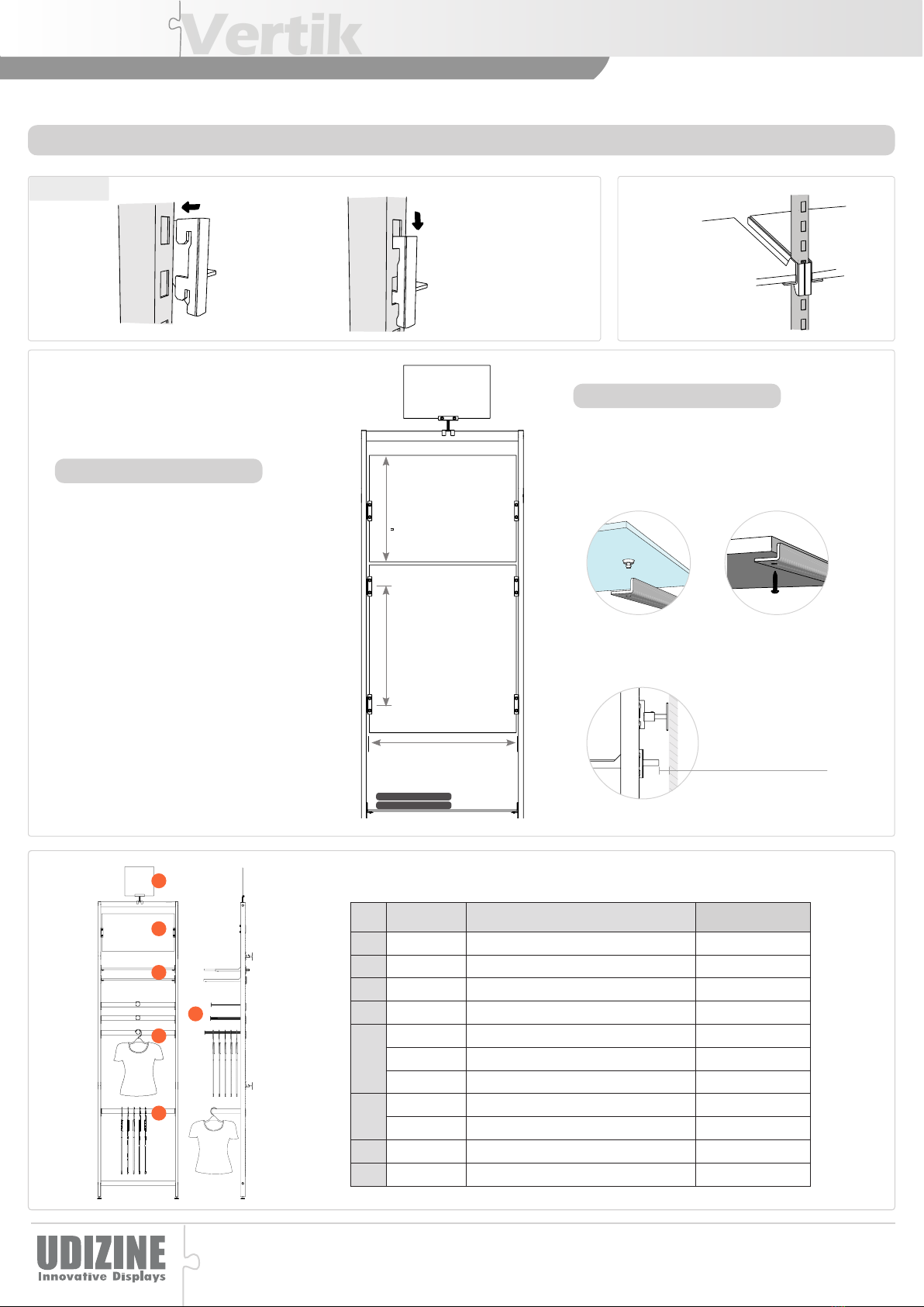
Item # Description Max Weight Load
VRS01-WB Wall Unit - Base 400lbs
VRS01-WE Wall Unit - Add-On 400lbs
1 VR19DB Hangbar for Clothing 44lbs
2 VR110DB Hangbar for Accessories 66lbs
3VR113DB 10” Faceout Ø3/4” 44lbs
VR114DB 12” Faceout Ø3/4” 37lbs
VR120DB 10” Faceout Ø5/16” 22lbs
4VR115DB 10” Shelf Bracket for 10”-12” shelves 55lbs Per Shelf
VR116DB 14” Shelf Bracket for 12”-14” shelves 44lbs Per Shelf
5 VR119DB Side Sign/Mirror 22lbs
6 VR118DB Sign Displayer 9lbs
Max Weight Load
Accessories
1
2
3
4
5
6
Assembly
Slide into slits at
the desired height
Slide down with a little
pressure.
Note: make sure its fully
inserted into position.
Each slit can hold
two accessories
Letter/ A5
Max. 12”Max. 32”
23 7/8”
Multiple
Support
Single
Support
Shelf
Required Shelf Width:
23 7/8” include edge banding
Shelf Type & Thickness:
Signage
Sign Width: 23 7/8”
Sign Type:
Acrylic and Poster PVC foam
bord
Sign Thickness:
Up to 1/4” Glass Shelf:
1/4” - 3/8”
Wood Shelf:
3/4” Min.
Allow 1” from the wall
to shelf, to easily change
the shelf location
1”

Other UDIZINE Indoor Furnishing manuals

UDIZINE Palo System IPSK002 User manual

UDIZINE

UDIZINE Palo System IPSK002 User manual

UDIZINE SW196SP User manual

UDIZINE

UDIZINE SW196SP User manual

UDIZINE Vertik User manual

UDIZINE

UDIZINE Vertik User manual

Popular Indoor Furnishing manuals by other brands

ME MARCKERIC 13142 Assembly instructions

ME MARCKERIC

ME MARCKERIC 13142 Assembly instructions

Workspace Office 9400994926484 Assembly instructions

Workspace Office

Workspace Office 9400994926484 Assembly instructions

Suncast ML141 owner's manual

Suncast

Suncast ML141 owner's manual

La Redoute GFW075 manual

La Redoute

La Redoute GFW075 manual

Wampat M/CAT1501W Assembly instructions

Wampat

Wampat M/CAT1501W Assembly instructions

Sedus quarterback Instructions for use

Sedus

Sedus quarterback Instructions for use

Walker Edison W52FPCLA2D Assembly instructions

Walker Edison

Walker Edison W52FPCLA2D Assembly instructions

Woltra SILKEBORG SI-85 Assembly instructions

Woltra

Woltra SILKEBORG SI-85 Assembly instructions

Hillsdale Furniture PARK AVENUE NON-SWIVEL DINING CHAIR Assembly instructions

Hillsdale Furniture

Hillsdale Furniture PARK AVENUE NON-SWIVEL DINING CHAIR Assembly instructions

Mäusbacher Tischplatte/180 Assembly instructions

Mäusbacher

Mäusbacher Tischplatte/180 Assembly instructions

Teknion RKXD Installation guides

Teknion

Teknion RKXD Installation guides

Stellar Home S 200 Assembly instructions

Stellar Home

Stellar Home S 200 Assembly instructions

PHI VILLA THD5-119-5901 Use and care guide

PHI VILLA

PHI VILLA THD5-119-5901 Use and care guide

Clou hammock CL/07.66.304 Series installation instructions

Clou

Clou hammock CL/07.66.304 Series installation instructions

FourStarGroup 11212833A manual

FourStarGroup

FourStarGroup 11212833A manual

Ryvyr KARA V-KARA-30DE installation instructions

Ryvyr

Ryvyr KARA V-KARA-30DE installation instructions

Hobby PRO-018-4101 manual

Hobby

Hobby PRO-018-4101 manual

Howdens RKLENBUOH Assembly

Howdens

Howdens RKLENBUOH Assembly

manuals.online logo
manuals.online logoBrands
  • About & Mission
  • Contact us
  • Privacy Policy
  • Terms and Conditions

Copyright 2025 Manuals.Online. All Rights Reserved.