manuals.online logo
Brands
  1. Home
  2. •
  3. Brands
  4. •
  5. UFM
  6. •
  7. Measuring Instrument
  8. •
  9. UFM UFM-40 Series Manual

UFM UFM-40 Series Manual

Page 3 of 51
Product Components
Inspection should be made before installing the Flowmeter. Check to see if the spare parts are in accordance with
the packing list. Make sure that there is no damage to the enclosure due to a loose screw or loose wire, or other
damage that may have occurred during transportation. Any questions, please contact your representative as soon
as possible.
UFM-40 Ultrasonic transit-time flowmeter
Page 4 of 51
Content
1. Transmitter Installation and Connection.....................................................................................................6
1.1. Inspection Prior to Transmitter Installation .............................................................................................. 6
1.2. Wire Connecting ............................................................................................................................................... 7
1.2.1 Power Supply Option ................................................................................................................................ 7
1.2.2 Transmitter Wiring ..................................................................................................................................... 7
1.2.3 Lengthened Cable Method ...................................................................................................................... 7
1.3. Powering On ...................................................................................................................................................... 8
1.4. Keypad Functions ............................................................................................................................................. 9
1.5. Keypad Operation ............................................................................................................................................ 9
1.6. Flowmeter Window Descriptions .............................................................................................................. 10
2. Pipe Parameter Entry Shortcuts.................................................................................................................... 11
2.1. Dual Function Keys Menu Description ................................................................................................... 11
2.2 Examples ............................................................................................................................................................ 12
3. Measurement Site Selection.............................................................................................................................14
4. Transducer Installation .....................................................................................................................................15
4.1 Installing the transducers ............................................................................................................................... 15
4.1.1Transducer Spacing .................................................................................................................................. 15
4.1.2 Transducer Mounting Methods ............................................................................................................ 15
4.1.3 V Method .................................................................................................................................................... 15
4.1.4 Z Method .................................................................................................................................................... 16
4.1.5 N Method (not commonly used) .......................................................................................................... 16
4.2 Transducer Mounting Inspection ................................................................................................................. 16
4.2.1 Signal Strength .......................................................................................................................................... 16
4.2.2 Signal Quality (Q value) ........................................................................................................................ 17
4.2.3 Total Time and Delta Time .................................................................................................................... 17
4.2.4 Transit Time Ratio ................................................................................................................................... 17
4.2.5 Warnings ..................................................................................................................................................... 17
5. Operating Instructions.......................................................................................................................................19
5.1 System Normal Identification ...................................................................................................................... 19
5.2 Zero Set Calibration ........................................................................................................................................ 19
5.3 Scale Factor ....................................................................................................................................................... 19
5.5 Frequency Output ............................................................................................................................................ 20
5.6 4~20mA Current Loop Output Verification (Optional) ........................................................................ 20
UFM-40 Ultrasonic transit-time flowmeter
Page 9 of 51
The system will default to the last window settings and automatically display them at next power on.
1.4. Keypad Functions
This keypad is dual function keypad:
1. When separately pressed, is shortcut function, referring to "2. Quickly set menu instructions ";
2. Press and Number key, is Menu key, referring to"6.Menu Window Description".Follow these
guidelines when using the Flowmeter keypad (Refer to Keypad Figure):
~ And To input numbers.
Backspace or delete characters to the left.
And Return to the last menu or to
open the next menu. Acts as "+" and "-" functions
when entering numbers.
Select a menu. Press this key first, input two
menu numbers and then enter the selected menu. For
example ,to input a pipe outside diameter, press
keys, where "11" is the window
ID to display the parameter for pipe outside diameter.
1.5. Keypad Operation
The flow meter adopts the window software design to consolidate or subdivide all of the parameters entered, the
instrument setup and measurement result displays into more than 100 independent windows. The operator can
input parameters, modify settings or display measurement results by "visiting" a specific window. These windows
are arranged by 2-digit serial numbers (including "+" sign) from 00~99, then to +0, +1, etc. Each window serial
number, or so-called window ID code, has a defined meaning. For example, Window M11 indicates the parameter
input for pipe outside diameter, while Window M25 indicates the mounting spacing between the transducers, etc.
(Refer–Windows Display Explanations).
The keypad shortcut to visit a specific window is to press the key at any time, then input the 2-digit
window ID code. For example, to input or check the pipe outside diameter, just press the
keys for window ID code 11.
Another method to visit a particular window is to press and keys to scroll the screen. For
example, if the current window ID code is M02, press key to enter Window M01, press the
button again to enter Window M00; then, press the key to back Window M01, and press the key
again to enter Window M02.
Windows are separated into three types: (1) Data Type, such as M11, M12; (2) Option Type, such as M14; (3)
Pure Display Type, such as M01, M00.
You can check the corresponding parameters by visiting the Data Type Windows. If you want to modify the
parameters, input the digits and press or press first, input the digits then press again to
confirm.
UFM-40 Ultrasonic transit-time flowmeter
Page 14 of 51
3. Measurement Site Selection
When selecting a measurement site, it is important to select an area where the fluid flow profile is fully developed
to guarantee a highly accurate measurement. Use the following guidelines to select a proper installation site:
Choose a section of pipe that is always full of liquid, such as a vertical pipe with flow in the upward direction or a
full horizontal pipe.
Ensure enough straight pipe length at least equal to the figure shown below for the upstream and downstream
transducers installation.
Ensure that the pipe surface temperature at the measuring point is within the transducer temperature limits.
Consider the inside condition of the pipe carefully. If possible, select a section of pipe where the inside is free of
excessive corrosion or scaling.
UFM-40 Ultrasonic transit-time flowmeter

This manual suits for next models

1

Other UFM Measuring Instrument manuals

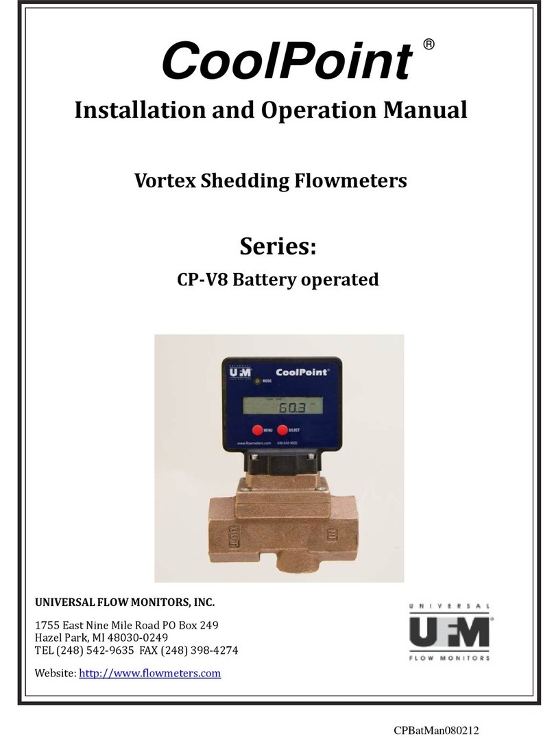
UFM CoolPoint CP2-V8 User manual

UFM

UFM CoolPoint CP2-V8 User manual

UFM UFM-50 Manual

UFM

UFM UFM-50 Manual

UFM KATflow 200 User manual

UFM

UFM KATflow 200 User manual

UFM KATflow 210 User manual

UFM

UFM KATflow 210 User manual

Popular Measuring Instrument manuals by other brands

Sonel MRU-11 user manual

Sonel

Sonel MRU-11 user manual

Lutron Electronics AM-4215SD manual

Lutron Electronics

Lutron Electronics AM-4215SD manual

Minnich MINNICH Operators & service manual

Minnich

Minnich MINNICH Operators & service manual

Tektronix PA4000 Series Manual addendum

Tektronix

Tektronix PA4000 Series Manual addendum

Vega VEGAPULS SR 68 operating instructions

Vega

Vega VEGAPULS SR 68 operating instructions

Anritsu MS2690A Operation manual

Anritsu

Anritsu MS2690A Operation manual

Time Electronics 1049 Technical manual

Time Electronics

Time Electronics 1049 Technical manual

Rohde & Schwarz R&S NRPM user manual

Rohde & Schwarz

Rohde & Schwarz R&S NRPM user manual

Veris Industries FSR Series installation guide

Veris Industries

Veris Industries FSR Series installation guide

GLI International GLI-98144 operating manual

GLI International

GLI International GLI-98144 operating manual

ZyXEL Communications VANTAGE REPORT 2.3 - datasheet

ZyXEL Communications

ZyXEL Communications VANTAGE REPORT 2.3 - datasheet

Berner 169091 Operation manual

Berner

Berner 169091 Operation manual

Hanna Instruments HI97706 instruction manual

Hanna Instruments

Hanna Instruments HI97706 instruction manual

Laserworld RED-200-640 manual

Laserworld

Laserworld RED-200-640 manual

Topcon IM-1000 instruction manual

Topcon

Topcon IM-1000 instruction manual

IVDT SkidWeigh ED2-SM Series Installation & Calibration Manual

IVDT

IVDT SkidWeigh ED2-SM Series Installation & Calibration Manual

SMART SMART PE260 quick start guide

SMART

SMART SMART PE260 quick start guide

BIONIME Rightest GM700 Getting started guide

BIONIME

BIONIME Rightest GM700 Getting started guide

manuals.online logo
manuals.online logoBrands
  • About & Mission
  • Contact us
  • Privacy Policy
  • Terms and Conditions

Copyright 2025 Manuals.Online. All Rights Reserved.