Uhlenbrock Elektronik IntelliLight LED User manual

- 1 -
Manual

- 2 -
Contents
1. Description 3
2. The Components 3
3. Technical Data 3
4. Installation of the Lighting System 4
4.1 Light requirement and Positioning 4
4.2 Mounting the Lighting Sticks 4
5. Connection 5
5.1 The Main Lighting Stick Connecting Sockets 5
5.2 Connecting the Control Module 5
5.3 Connecting Lightning & Sound 5
5.4 Connecting LED Luminaires 6
5.5 Connecting LocoNet for Digital operation 6
5.6 Connecting the IntelliLight 28 000 6
6. Operation 7
6.2 Operating using Key switches (analog) 7
6.2 Operation via Solenoid addresses (digital) 8
7. Synchronization with a LocoNet Clock 8
8.1 Calling up a Control Module with an Intellibox II 9
8.2 Reading and programming of an IntelliLight LED Control Module 10
8.3 The Universal Address 65535 11
9. LNCV Table 11
10. Safety Notice 12
11. Package Contents 12
11.1 IntelliLight LED Starter set 28 200 12
11.2 IntelliLight LED Main Lighting Stick 28 220 12
11.3 IntelliLight LED white Lighting stick 28 210 12
11.4 IntelliLight LED Expansion Lightning & Sound 28 230 12

- 3 -
1. Description
IntelliLight LED gives you realistic lighting for your model railway layout. IntelliLight
LED illuminates your layout depending on the time of day and weather.
When you switch the lighting system on it starts at dawn. The sun rises after a
magnificent morning red. If the sun sets again after an eventful day the moon bathes
the entire layout in a mysterious silvery light.
According to the conditions the weather is radiantly beautiful or gloomy. Now and then
it rains or a thunderstorm passes through and lightning flashes and it thunders.
The routine of the day, with an adjustable time, is started when the layout is switched
on. The kind of the lighting depends on the time and cloudy appearance.
Thunderstorms and rain appear randomly or by the push of a button.
Depending on programming,the day passes in 24 hours or up to 20 times faster, in
approximately 1¼ hours. The lighting can be switched manually or time controlled
automatically.
All pre-programmed time tables can be changed in duration and intensity by LNCV
programming according to one’s own wish. The system can be used with analog and
digital layouts. The lighting system is powered with a normal Model railway
transformer.
2. The Components
IntelliLight LED Start Set Part No. 28 200
The Starter set consists of a Control Module 28 200, a power plug pack, a main lighting
stick, two white lighting sticks and connecting cables. The overall length of the
connected lighting sticks is 1050 mm.
Main lighting stick Part No. 28 220
with four white, two red and a blue power LED and includes the power plug pack and
connecting cable for connecting to the IntelliLight-Net. With sockets to connect further
white lighting sticks. Length: 350 mm
White lighting stick Part No. 28 210
with four white power LEDs. Length: 350 mm
Expansion unit –Lightning & Sound Part No. 28 230
with a strobe lamp and an IntelliSound 4 Module "Rain and Thunder" with a connected
8 Ohm, 3 W Loudspeaker.
3. Technical Data
Power load of the Main lighting stick 28 220
6 VA
Power load of the white lighting stick Part No. 28 210
5 VA
Power plug pack
15 V, 1.9 A, 1.9 m
Dimensions of the Control Module
105 x 58 x 35 mm
Dimensions of Main lighting stick
350 x 16 x 17 mm
Dimensions of white lighting stick
350 x 8 x 4 mm
Maximum surface temperature of the Power LEDs
90° C

- 4 -
4. Installation of the Lighting System
Safety Notice: Never look directly into the switched on LEDs. Because of their intense
brightness they may damage your eyes.
Safety Notice: Do not touch the switched on LEDs. Because of their high temperature
there is a risk of injury.
4.1 Light requirement and Positioning
NOTE: Both the illumination requirement and positioning of the lighting sticks greatly
depend on the design of the layout and its presentation.
For optimal lighting of a layout of a depth of up to
1.5m per running metre, one lighting unit is needed.
Therefore a layout with an edge length of 1m can be
illuminated with an IntelliLight LED Starter set (a
main lighting stick, 2 white lighting sticks). In order to
arrange the lighting effect correctly with sunrise
(morning red) and sunset (evening red), as well as
the night effect, two white and one coloured unit are
required.
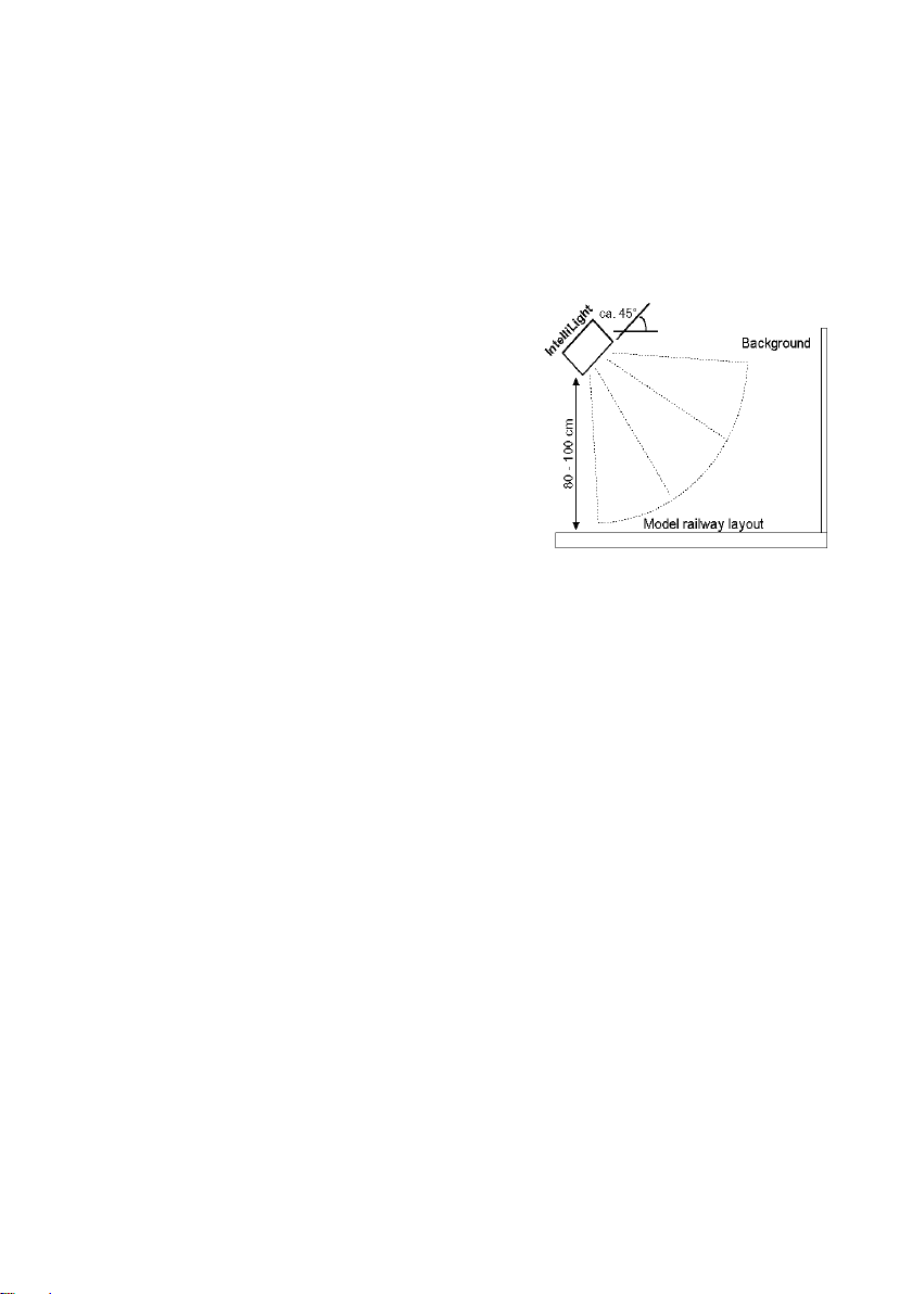
Depending on desired light intensity, the lighting
sticks should be attached at 45° angle (approx) at
a min. distance of 80cm above the layout surface.
The lighting sticks should be fitted to the front edge of the layout to light up the scene.
It has proven useful to fasten the lighting sticks to a common base board. This board
is then hung at an appropriate height from the room ceiling with chains. The length of
the chains can be adjusted to provide the desired lighting effect on the layout surface.
4.2 Mounting the Lighting Sticks
Each lighting stick has two 3.3mm mounting holes for screwing the lighting sticks to a
suitable base (e.g. wood strip).
Mount the main lighting stick.
If you use additional white lighting sticks, insert the 3-way plug from one of the white
lighting sticks into the 3-way socket of the main lighting stick. Then screw the white
lighting stick to the base.
Up to 4 white lighting sticks can be supplied from one main lighting stick. The white
lighting sticks can be attached either to the right or the left of the main lighting sticks.
If needed, an additional main lighting stick can be placed at any location and white
lighting sticks can be connected to that as required.

- 5 -
5. Connection
5.1 The Main Lighting Stick Connecting Sockets
1 –Connector for power plug pack 15 V DC, 1.9 A
2 –Connector for LED luminaire: 12 V, max. 2W, dimmable
3 - SUSI-Interface for the Sound module
4 - Connector strobe lamp
5 - 2x Connector IL-Net
6 - 2x Connector white Lighting stick
The 6 m IntelliLight-Net cable, from the Starter set, is connected from the first main
lighting stick to the "IL-NET" socket on the Control Module. When numerous main
lighting sticks are used, they are connected to each other with the enclosed IntelliLight-
Net cable.
To supply power to the lighting sticks use the provided power plug pack for each main
lighting stick. Plug this into the "DC in" socket on the Main lighting stick and then into a
suitable 230V~ power outlet.
5.2 Connecting the Control Module
Both the IL-Net and the LocoNet sockets are on the back of the unit.
Pin allocation on the screw terminal connector for analogue operation
LED –Display model clock speed
Key 3 –Change model time
Key 2 –trigger long thunderstorm
Key 1 –Day/Night change over
Chassis / Return wire for keys and LED
If the lighting system is used with analogue DC or AC layout or a digital center without
LocoNet output, the system can be controlled by simple push keys. Any potential free
momentary switches can be used as the keys.
Connect the keys and LED to the 5-way terminal according to sketch above.
For digital operation connect the Control Module LocoNet socket with the LocoNet
socket on the digital center.
5.3 Connecting Lightning & Sound
The Lightning & Sound expansion consists of two parts: the strobe lamp and the Intelli-
Sound 4-Module "Rain and Thunderstorm" with connected loudspeaker.

- 6 -
Strobe lamp:
The strobe lamp is attached to the mount with 2 screw lugs on the base board. The
plug from the strobe lamp is plugged into connector 4 (Blitz (Strobe)) on any main
lighting stick.
Chassis, white
Lightning power, yellow
Sound module:
Plug the small four way SUSI connector from the Sound module into connector 3
(SUSI) of any Main lighting stick. Attach the Sound module with the enclosed adhesive
pad close to the SUSI socket. Attach the loudspeaker as required, close to the Sound
module.
5.4 Connecting LED Luminaires
For precise illumination (e.g. Spot) a dimmable 12V LED Luminaire can be connected
to the 2-way screw terminal. The maximum load capacity of the luminaire is 2 W.
Take care on the correct polarity. In the diagram of the main lighting stick (see Chap
5.1) the terminal is marked with "+" and "-".
5.5 Connecting LocoNet for Digital operation
In order to trigger the light or weather events with solenoid addresses, for example, or
from the IntelliLight LED to switch the house lights in synch with the time of day,
connect the LocoNet socket from the control module with the LocoNet of your digital
center (Intellibox, DAISY II DCC Digitalset, SC7, Märklin 6021 with 6021-Infrared &
LocoNet-Adapter, TwinCenter, Piko Power Box). Use the 60 cm LocoNet cable from
the Starter set.
5.6 Connecting the IntelliLight 28 000
If an IntelliLight 28 000 already exists and is to be extended with an IntelliLight LED the
main lighting stick from IntelliLight LED connector 5 is connected with the data line
from the IntelliLight 28 000 as shown in the sketch. For that the 4-way connector
socket on the base unit 28 000 or an expansion unit 28 010 or 28 020 can be used.
For this connection you must make an appropriate cable from a LocoNet cable. Cut a
plug off a LocoNet cable and approximately 5cm of the outer insulation. Now connect
the wires as follows, (e.g. soldering or terminal clips) wires 2 and 5 together. After that
3 and 4. The resulting double line 2 & 5 is screwed to terminal 2 (GND) of the
connector on the IntelliLight Base or Expansion module. Double line 3 & 4 is then
connected to terminal 3 (LN) of the connector. Wires 1 and 6 of this LocoNet cable
remain insulated and unused.

- 7 -
6. Operation
The lighting system is controlled by an internal model clock.
Sunrise is set at 7:00 o'clock and sunset at 19:00. Weather events (cloudy
appearance, rain and thunderstorm) are randomly inserted in the daily and night
sequence.
When the lighting system is switching on, the model clock is set at 7:00 o'clock and so
the sunrise occurs. Sunrise, sunset and up to 8 different weather events can be
activated by key instruction.
Furthermore, the system can be brought into a layout service mode. For this all white
Power-LEDs, and also the "LED Luminaire" output are switched to maximum
brightness. As well the system clock is switched on, so that this state is not
independently changed.
6.2 Operating using Key switches (analog)
If the lighting system is used with an analog DC or AC layout or a digital center which
does not have a LocoNet output you can operate the lighting using push button keys.
(Connection see Chap. 5.2).
The following applies:
Key
Event
1
Skip the timing to the next Sunrise or Sunset
2
Long thunderstorm
3
The time reductions 1:1, 1:2, 1:3, 1:6, 1:12 and 1:20 adjust model clock
are scrolled by successive key presses. The LED on connection 2
shows the 1 second pulse of the model clock.

- 8 -
6.2 Operation via Solenoid addresses (digital)
If the light system is operated from a digital center with LocoNet connection (see 5.5),
the individual events are switched using the following solenoid addresses:
Solenoid address
Setting
Event
193
Red
Sunset
Green
Sunrise
194
Red
Random event 1: Cloudy
Green
Random event 2: Rain
195
Red
Random event 3: Short thunderstorm
Green
Random event 4: Long thunderstorm
196
Red
Not used
Green
Not used
197
Red
Not used
Green
Not used
198
Red
Service mode off, if switched on and System restart
Green
Service mode on: white lights and Halogen to
maximum intensity and hold clock
Many system properties described in this chapter can be reprogrammed. In the
"Programming" chapter the basic changes are described.
The changes to the time sequence and the individual events is described in an
additional comprehensive document, which is available in PDF format on our website,
www.uhlenbrock.de.
7. Synchronization with a LocoNet Clock
The light system’s internal clock synchronizes to a LocoNet Mode Clock, if LNCV 9 is
programmed to the starting time above 10000. The lighting system then starts with the
programmed time and afterwards synchronizes to the system time via the LocoNet. If
LNCV 9 is set to value 10000 the light system starts the clock with the first LocoNet
sync signal.
If the light system’s clock is in the LocoNet synchronization mode the time and time
reduction are controlled by the LocoNet.
If the time of a LocoNet clock is adjusted by hand, then the changes are likewise
transferred in the clock of the light system. If a change from day to the night should
result or in reverse, then the sunrise or the sunset occurs.
If the time on a LocoNet clock is manually changed it flows through the lighting system.
Should this result in a change of day to night or vice-versa sunset or sunrise will be
activated.
If a LocoNet display 63450 is used as LocoNet clock then LNCV 34 of the display must
be set to a value of 1. On changing of the time by hand, the change flows through to
the light system, at the latest, after the time period in the display’s LNCV 35.
8. LocoNet Programming
LocoNet devices are setup using LocoNet configuration variables (LNCV’s). These
LNCV’s can be change with help of an Intellibox (from Software-Version 1.3), the IB-
Control (from Version 1.55) or the TwinCenter (from Version 1.1).

- 9 -
8.1 Calling up a Control Module with an Intellibox II
Connect the module to the LocoNet.
Press the [mode]-Key to access the main selection Menu:
Press the "LocoNet Programming" button:
Press the "Part number" button, and enter the part number of the IntelliLight LED
control module (here 28200) and press the []-key.
Press the "Module Number" button, enter the module address for the module (in a
new module this is 1) and press the []-key:
Press the "Prog.mode on" button:
Now the IntelliLight LED Control module is in Programming mode.

- 10 -
Important: In the event that a number of IntelliLight LED Base units are to be
controlled by one Intellibox, every IntelliLight LED Base unit requires a different module
address, so the digital centre knows which base unit is being referenced during
programming. The factory default address of an IntelliLight LED module is 1. If further
IntelliLight LED Base units are controlled by a centre they must have different module
addresses. Valid addresses are 1 to 65534.
8.2 Reading and programming of an IntelliLight LED Control Module
Similarly to DCC locomotive decoders, IntelliLight LED modules operation is setup in
various configuration variables (CV). Contrary to locomotive decoders they are not
programmed via the rails but via the LocoNet and are therefore called LocoNet CV’s
(LNCV’s).
After calling up the IntelliLight LED module (see Chapter 8.1) the Intellibox display
shows:
Press the "LNCV" selection button, enter the ID number of the LNCV (here "0") and
press the []-key. LNCV 0 is read directly and the value is displayed behind the
"Value" line (in the example value "1"):
To change the LNCV, press the "Value" selection button, enter the new value (here
in the Example "2") and press the []-key:
To program the value into the module also press the "Program" button on the right
hand side. The LNCV is now programmed. You can press the "Read" button to
verify that the programming was successful.
Additional LNCVs can be programmed or returned to normal operating mode with the
"Prog.mode off" button.

- 11 -
Exit the Programming Menu "Back". After that return to the Controller mode with the
[mode]-Key.
NOTE: For other LocoNet centers there are similar procedures for LNCV
Programming. Use the precise steps outlined in the corresponding manual.
8.3 The Universal Address 65535
With the universal address can call up all IntelliLight LED modules.
The universal address is not a valid address that can be used for identifying different
IntelliLight LED modules. It can only be used for calling up modules whose real
address is not known. For this only the particular module that is being tested can be
connected to the LocoNet. If the module is then called up the current address can
then be read from LNCV 0.
9. LNCV Table
LNCV
Description
Value
Range
Factory
Default
0
Module address
1-65534
1
1
Solenoid address for sunrise (green) and
sunset (red)
1-2000
192
2
Solenoid address for Random event 1 (red)
and 2 (green)
1-2000
193
3
Solenoid address for Random event 3 (red)
and 4 (green)
1-2000
194
4
Solenoid address for Random event 5 (red)
and 6 (green)
1-2000
195
5
Solenoid address for Random event 7 (red)
and 8 (green)
1-2000
196
6
Solenoid address for Service mode
green = on, red = off
1-2000
197
7
Reduction of the model time relative to the
standard time factor 1: (100/LNCV value)
5 -100
5
8
Reduction of the events relative to the
standard time factor 1 : (100/LNCV value)
5 -100
5
9
Time when starting the system.
An LNCV value of 1330 corresponds to the
time of 13:30
0-2400
700
2047
Software Version (read only)
-
varies.
Changing of the timed sequences and individual events are outlined in the technical
description. This is available as a PDF Document for download from our internet site
www.uhlenbrock.de.

- 12 -
10. Safety Notice
Read the manual and safety notice well before use.
These devices are not toys and not suited for children aged under 14! They can
however be used by children under the supervision of experienced adults.
Never plug the connecting cables into a power outlet!
Check the power plug pack regularly for damage to cables, plug, housing etc. Never
use a damaged power plug pack!
Never look directly into the switched on LEDs. Because of the high brightness your
eyes could be damaged.
Do not touch the switched on LEDs. Because of the high temperature you could risk
an injury.
Keep this manual handy.
11. Package Contents
11.1 IntelliLight LED Starter set 28 200
1x Control Module
1x Main Lighting stick
2x white Lighting sticks
1x Power Pack 15 V, 1.9 A, 1,9 m
2x Connecting cables 2.15 m
11.2 IntelliLight LED Main Lighting Stick 28 220
1x Main Lighting stick
1x Power Pack 15 V, 1.9 A, 1,9 m
1x Connecting cable 2.15 m
11.3 IntelliLight LED white Lighting stick 28 210
1x white Lighting stick
11.4 IntelliLight LED Expansion Lightning & Sound 28 230
1x IntelliSound 4 Module "Rain & Thunderstorm"
1x Loudspeaker 8 Ohm, 3 W
1x Strobe lamp
02045-858327
If you have any questions call us. Hotline times are:
Mon - Tue - Thu - Fri., 14:00-16:00 and Wednesdays 16:00-18:00
Should it be urgent. The Premium Hotline: 0900-1858327
Mon –Fri 10:00 –16:00 Fee applies (98cent/min landline, mobile more expensive)
This product has a two year warrantee. If it is defective
send decoder along with the receipt of purchase to the following address:
Uhlenbrock Elektronik GmbH Mercatorstr. 6 D - 46244 Bottrop
Tel: 02045-85830 Fax: 02045-86840 www.uhlenbrock.de
Electronic devices
do not belong in
the household
rubbish
This manual suits for next models
1
Table of contents
Popular Lighting Equipment manuals by other brands

Sygonix
Sygonix 1323078 operating instructions

LDR
LDR Tono 8/22 Plus operating instructions

DTS
DTS Raptor user manual

Vision & Control
Vision & Control R-CLR-132x104-G523-SL Installation and operating instructions

JLG
JLG METRO-MH Operation and safety manual

HEPER
HEPER AQSA 1 m Installation & maintenance instructions