uhlmann & zacher CX2936 User manual

CX2936
Clex private wireless switch module
with Bluetooth® Low Energy
Operating and
installation instructions

CX2936 TABLE OF CONTENTS
1
Legal Notice
Operating and installation instructions (original language)
Clex private wireless switch module with Bluetooth® Low Energy CX2936
Document number: 151A
Version: 1.0
Date: 13.02.2023
Manufacturer
Uhlmann & Zacher GmbH
Gutenbergstraße 2–4
97297 Waldbüttelbrunn
Germany
Tel.: +49 931 40672-0
www.UundZ.de
These operating and installation instructions are protected by copyright. The in-
formation contained here may not be reproduced, distributed or used for compet-
itive purposes or provided to third parties. It is also prohibited to manufacture any
component using these instructions without prior written consent.

CX2936 TABLE OF CONTENTS
2
Table of contents
1About this document ........................................................................ 3
1.1 Warnings ............................................................................................3
1.2 Symbols..............................................................................................3
2Safety ............................................................................................ 4
2.1 Proper use ..........................................................................................4
2.2 Improper use.......................................................................................4
2.3 General safety information ...................................................................4
3Product description .......................................................................... 5
3.1 Functional description ..........................................................................5
3.2 Versions..............................................................................................6
3.3 Technical data ....................................................................................6
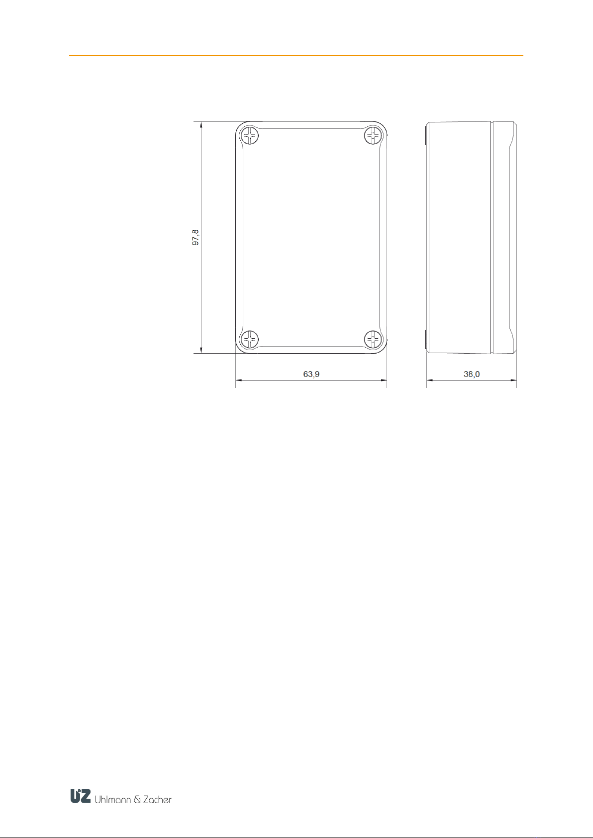
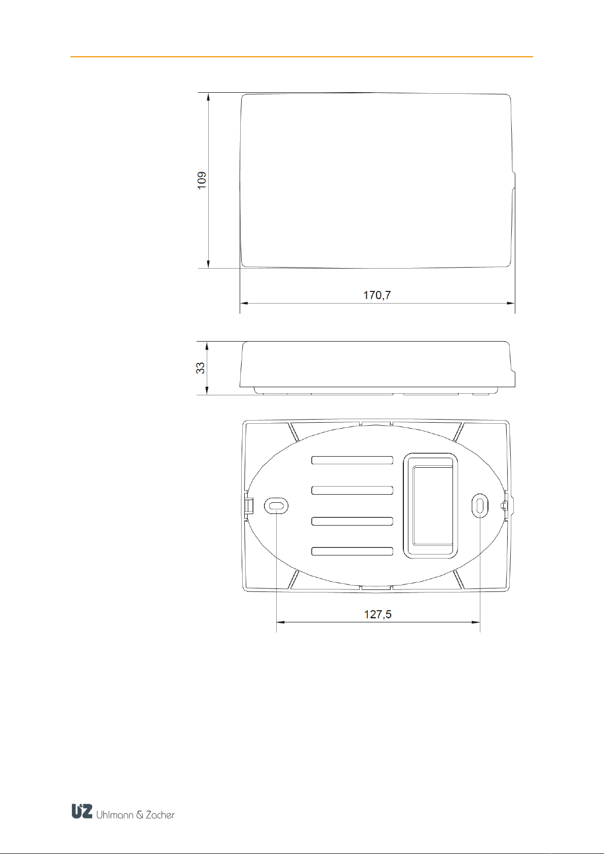
3.4 Dimensions .........................................................................................7
4Installation.....................................................................................10
4.1 General installation information..........................................................10
4.2 Installation ........................................................................................10
4.3 Pin assignment ..................................................................................11
5Commissioning and operation .........................................................12
5.1 Connecting the locking unit ................................................................12
5.2 Operation.........................................................................................13
5.3 Resetting...........................................................................................13
5.4 Resetting the configuration (factory reset) .............................................13
5.5 Firmware updates ..............................................................................13
5.6 Signaling ..........................................................................................13
5.7 Malfunctions during operation/error signaling......................................13
6Maintenance and cleaning...............................................................15
6.1 Maintenance .....................................................................................15
6.2 Cleaning...........................................................................................15
7Disposal........................................................................................16
8Glossary........................................................................................17

CX2936 ABOUT THIS DOCUMENT
3
1About this document
These operating and installation instructions describe the CX2936 Clex private
wireless switch module with Bluetooth® Low Energy (short: CX2936). They are
part of the product and contain important information required for correct opera-
tion and maintenance.
These operating and installation instructions apply for all versions of the CX2936
and are intended both for specialist personnel responsible for assembly and dis-
assembly and for end customers.
To ensure trouble-free and safe operation, read these operating and installa-
tion instructions carefully and observe the information contained there before
putting the door handle into operation.
Keep the operating and installation instructions.
After installation, give the instructions to the end customer and familiarize
them with operation.
Uhlmann & Zacher GmbH accepts no liability for malfunctions, such as impossi-
ble access to injured persons, operational malfunctions, damage to property or
other damage resulting from non-observance of these operating and installation
instructions or from incorrectly configured door handles.
If you still have any questions after reading these operating and installation
instructions, please contact your specialist dealer or Uhlmann & Zacher
GmbH directly.
1.1 Warnings
Warning notices warn of hazards that may occur when using the door handle.
There are two hazard levels, recognizable by the signal word:
Signal word
Meaning
CAUTION
Indicates a low-risk hazard that may result in minor or moderate
injury if not avoided
ATTENTION
Indicates a hazard that results in damage to property
1.2 Symbols
The following symbols may appear in this manual:
This symbol marks an instruction that has to be carried out by the user.
This symbol marks an entry in a list.
This symbol indicates useful and important information.

CX2936 SAFETY
4
2Safety
2.1 Proper use
The product is intended for use solely with Bluetooth® -capable devices. It is de-
termined for use in the system Clex private. The device is designed for the surface
mounting in secured indoor areas. Only components approved by Uhlmann &
Zacher may be used for installation and maintenance.
Installation may only be carried out by trained specialist personnel. Any other use
is considered improper and may result in damage to property or even personal
injury.
2.2 Improper use
The product must not be used to lock up aids that are vital in an emer-
gency (for example, defibrillators, emergency medication, fire extinguish-
ers, etc.).
The product must not be used in potentially explosive atmospheres.
If the housing or the electronics are damaged, the product must not be
operated any longer. Modifications or additions to the product are not
permitted. Usage outside the stated specifications is not permitted.
2.3 General safety information
Observe the following basic safety instructions when handling the wall mounted
reader:
No modifications of any kind are permitted to the product, with the ex-
ception of those described in this manual.
Installation may only be carried out by trained specialists in accordance
with these instructions.
The product must only be operated in the defined temperature range.
There is an increased risk of injury (electric shock!) if the connecting ca-
bles are touched when the power supply is switched on. Only perform in-
stallation and maintenance work when the power supply is switched off.
Observe VDE guidelines!
These instructions should be passed on to the user by the person carrying
out the installation.
The product must not be brought into contact with paints or acids
To avoid malfunctions and damage, only use original parts and accesso-
ries from Uhlmann & Zacher GmbH.

CX2936 PRODUCT DESCRIPTION
5
3Product description
3.1 Functional description
The wireless switch module is an extension of the Clex private locking system with
a wireless switch unit to control the Clex private locking cylinder or other Clex
private locking units. The wireless switch module can be controlled via the wall
reader of the Clex private system or via external readers (RFID reader, finger
print, PIN keyboard, etc.). The electronic locking units of the system Clex private
receive an opening command from the wireless switch module via the 2.4 GHz
range. There is a 1:1 assignment between the wireless switch module and the
locking unit. Layout and scope of delivery.
Layout using the example of the grey housing version. Other housing versions
similar:
1. Housing cover and screw(s)
1 screw for Part number 8936 0000 0000
4 screws for Part numbers 8936 0000 0004 and 8936 0000 0005
2. Housing bottom with electronics
3. Opening for cable feeding
4. Screw terminal for connection pins 1-8 (connection block pluggable)
5. Screw terminal for connection pins 9-16 (connection block pluggable)
6. Rotary switch
7. Button
8. LEDs
9. Mounting holes screws not included in the scope of delivery)

CX2936 PRODUCT DESCRIPTION
6
3.2 Versions
Housing versions:
Housing in grey
Oval housing in white
Rectangular housing in white
3.3 Technical data
3.3.1 General technical data
Designation
Value
Number of cou-
pleable locking units
1
Frequency range
2402 to 2480 MHz
Power supply
Supply voltage 5-24 VDC
Power consumption
Max. 0.4 W
Switching input
High: 5-24 VDC
Low: 0 VDC
3.3.2 Ambient conditions
Designation
Value
Operating tempera-
ture
+10 °C to +55 °C
Storage temperature
-40 °C to +65 °C
Installation location
Indoors

CX2936 PRODUCT DESCRIPTION
7
3.4 Dimensions
Grey housing

CX2936 PRODUCT DESCRIPTION
8
White oval
housing

CX2936 PRODUCT DESCRIPTION
9
White rectangular
housing

CX2936 INSTALLATION
10
4Installation
4.1 General installation information
The valid national regulations for electronic installations
(e.g. VDE regulations) must be observed.
The connecting cables must be available and laid.
Only operate the device at the correct operating voltage.
If possible, disconnect the load and operating circuits.
In the case of installation on metal surfaces or in direct proximity to metals,
the range as well as the communication between product and connected
locking units may be influenced negatively.
Avoid direct exposure to strong electromagnetic fields
Do not paint over, paste on or cover the wireless switch module.
4.2 Installation
Specify the mounting position. Ensure that the surface is smooth, dry and firm
enough. Do not place the units close to each other to avoid radio interfer-
ences.
Mark the fastening points through the bottom of the housing
(No. 9 in layout diagram).
If required, drill mounting holes into the mounting surface.
Insert the connection cables through the opening on the bottom into the
housing and cut and strip to a suitable length.
Hand-tighten the lower part of the device at the intended location using suit-
able flat-head screws. Installation material is not included in the scope of de-
livery. In case of cable feeding from the side, use additional fitting rubber or
plastic spacers. Ensure that the cable is not pinched.
Wire cables according to the respective pin assignment specified in the next
chapter. The two 8-pin connection blocks can be removed for easier installa-
tion.
Perform commissioning (see the "Commissioning" chapter).
Put on the housing cover and screw it tight.

CX2936 INSTALLATION
11
4.3 Pin assignment
Contact number
Pin assignment
1
+ power supply 5-24 VDC
2
–power supply (ground)
3
Input ground (isolated from the supply ground together
with Pin 6/7/8)
4
Wiegand 0 (not used)
5
Wiegand 1 (not used)
6
Input (not used)
7
Input (not used)
8
Input + (potential 5-24 VDC)
9
+ power supply 5-24 VDC
(can be used alternatively to 1)
10
–power supply (ground)
(can be used alternatively to 2)
11
RS485A (not used)
12
RS485B (not used)
13
RS485A (not used)
14
RS485B (not used)
15 + 16
Relay (not used)

CX2936 COMMISSIONING AND OPERATION
12
5Commissioning and operation
5.1 Connecting the locking unit
Perform the following steps to connect a locking unit with the wireless switch
module:
Bring the locking unit which you want to connect into the service mode by
holding the service key in front of the locking unit.
Use a screwdriver or a similar tool to turn the rotary switch (6) so that the
arrowhead points to Position 8. Then briefly press the button (7) to switch to
the pairing mode and teach in the locking unit within reach.
6) Rotary switch
7) Button
8) LEDs
If successful, the green LED lights up several times and the lock leaves the service
mode directly. If not successful, the red LED lights up several times and the lock
remains in the service mode.
The yellow LED flashes additionally to confirm the button input. The blue LED
flashes to signal the BLE activity.
Turn the rotary switch back to the home position.
Rotary switch position
Function
0
Home position
4
Briefly press the button (7) to set the wireless switch
module into service mode.
8
Briefly press the button (7) to perform the pairing of the
wireless switch module with the locking unit that is in
reach and in service mode or to delete an existing
paired locking unit.
9
Briefly press the button (7) to delete all the saved lock-
ing units and parameters.
Any
If you keep the button (7) pressed longer than 4 s and
then release it, the wireless switch module switches to
the service mode (as at Position 4).

CX2936 COMMISSIONING AND OPERATION
13
5.2 Operation
Trigger the opening of the connected locking unit via the third-party system con-
nected to connections 3 and 8. Connection 3 serves as ground.
Switching input: High: 5-24 VDC
Low: 0 VDC
The high level must be present for at least 25 ms to trigger the switching opera-
tion.
5.3 Resetting
Disconnect the device from the power supply.
5.4 Resetting the configuration (factory reset)
If you want to reset all the settings, proceed as follows:
Use a screwdriver or a similar tool to turn the rotary switch (6) so that the arrow-
head points to Position 9. Briefly press the button (7) to delete all the saved lock-
ing units and parameters.
5.5 Firmware updates
The update tool "Clex FW Prog" is available to
update the firmware. Contact your respective dealer or Integration partner.
5.6 Signaling
LED
Meaning
Blue
slow flashing
Device scans for paired locking unit
Blue
flashing
BLE activity with connected locking unit
Blue
constant lighting up
Paired locking unit is connected
Blue
rapid flashing
Device tries to wake up a locking unit in the "wake on
radio" mode (WOR)
Yellow
Button input
Red/green
flashing alternatingly
Connected with the locking unit in service mode
Green constant light-
ing + blue flashing
Service mode
After reset: One-time
all colors consecutive-
ly
Device has completed the initialization
5.7 Malfunctions during operation/error signaling

CX2936 COMMISSIONING AND OPERATION
14
LED
Meaning
Red and yellow flash
after a reset; after that
service mode
Mode wrong for the available firmware:
Perform a firmware update or set the mode manually.
Yellow lights constant-
ly after a reset
Micro-controller of the device is in the boot loader.
Perform a suitable firmware update.

CX2936 MAINTENANCE AND CLEANING
15
6Maintenance and cleaning
6.1 Maintenance
Since the device is not protected specially against dust, the product should be
checked regularly for dust deposits. The frequency depends on the dust level at
the operation site.
6.2 Cleaning
Clean the housing with a soft, lint-free and only slightly moistened cloth. When
cleaning do not use corrosive liquids or liquids that decompose plastic such as
benzine, turpentine, etc. Sharp detergents may damage or discolor the surface.
Do not use any detergents which act on a mechanical basis (e.g. scouring milk,
scouring sponge).
Free the electronics from dust with a suitable brush or by careful use of com-
pressed air at a sufficient distance.

CX2936 DISPOSAL
16
7Disposal
Do not dispose of the device with household waste, but at a municipal col-
lection point for special electrical waste in accordance with European Di-
rective 2002/96/EC.
Dispose of packaging as environmentally friendly recycling.

CX2936 GLOSSARY
17
8Glossary
Term
Meaning
BLE
Bluetooth®Low Energy
VDE
German "Verband der Elektrotechnik" [Registered Asso-
ciation of the Electrical, Electronic and Information
Technology]
Table of contents
Other uhlmann & zacher Lock manuals
Popular Lock manuals by other brands

BIO-key
BIO-key TouchLock XL instruction manual

Lefroy Brooks
Lefroy Brooks M1-4303 Installation, operating, & maintenance instructions

Knox
Knox KeySecure 5 Admin & user guide

National Cabinet Lock
National Cabinet Lock C8131 Dimensional drawing

CODELOCKS
CODELOCKS CL100 instructions

Ebelco
Ebelco 300-LED Installation instruction guide