UHVD PSU-DC-36-42-K Specification sheet

PSU-DC MANUAL Rev 3.0 31/10/22
PRODUCT INSTRUCTION MANUAL
Part No. PSU-DC-all types
Model Numbers:
PSU-DC-36-42-K - 36V 42A DC PSU K type thermocouple
PSU-DC-36-42-C - 36V 42A DC PSU C type thermocouple
PSU-DC-48-62-K - 48V 62A DC PSU K type thermocouple
PSU-DC-48-62-C - 48V 62A DC PSU C type thermocouple
PSU-DC-60-25-K - 60V 25A DC PSU K type thermocouple
PSU-DC-60-25-C - 60V 25A DC PSU C type thermocouple
PSU-DC-96-31-K - 96V 31A DC PSU K type thermocouple
PSU-DC-96-31-C - 96V 31A DC PSU C type thermocouple

Product Manual
Page 2 of 19 2022-10-31
Warnings
This equipment must be installed by qualified personnel.
Refer to the Operating Handbook for the proper use and maintenance of this
equipment. Failure to observe these instructions may result in safety hazards.
Service work must only be carried out by personnel who are aware of the
potential risks of working on live equipment.
The front panel mains switch must not be relied upon to provide adequate
isolation from the mains supply for servicing or maintenance purposes. If full
isolation is required, remove the mains input cable.
Equipment must be fully earthed to prevent dangerous electrostatic charge
build-up.
The user should be aware of the potentials that may exist on any vacuum
feedthrough connections. Avoid contact with the Thermocouple vacuum
feedthroughs, especially if they are not grounded.
It is the responsibility of the user to consider the safety requirements of
hazardous materials used with this equipment and the consequence of any
leakage, however caused. Consider possible reactions with materials of
construction. Any equipment returned to UHV Design Ltd must have the
correct Declaration of Contamination securely fastened to the outside of the
packaging.
Take great care when changing any of the temperature control loop
parameters; this could have a serious effect on the stability of the control
system.
Do not operate the DC Power Controller unit with any of the covers removed.
Allow adequate ventilation around unit, keep bottom cover rear clear and do
not cover rear panel fan.

Product Manual
Page 3 of 19 2022-10-31
TABLE OF CONTENTS
1INTENDED TO USE............................................................................................................4
2UNPACKING AND INSPECTION.......................................................................................4
3INSTALLATION..................................................................................................................6
3.1 Mains Input Power ..................................................................................................6
3.2 Fusing......................................................................................................................6
3.3 Mains Input..............................................................................................................6
3.4 Earth Stud ...............................................................................................................6
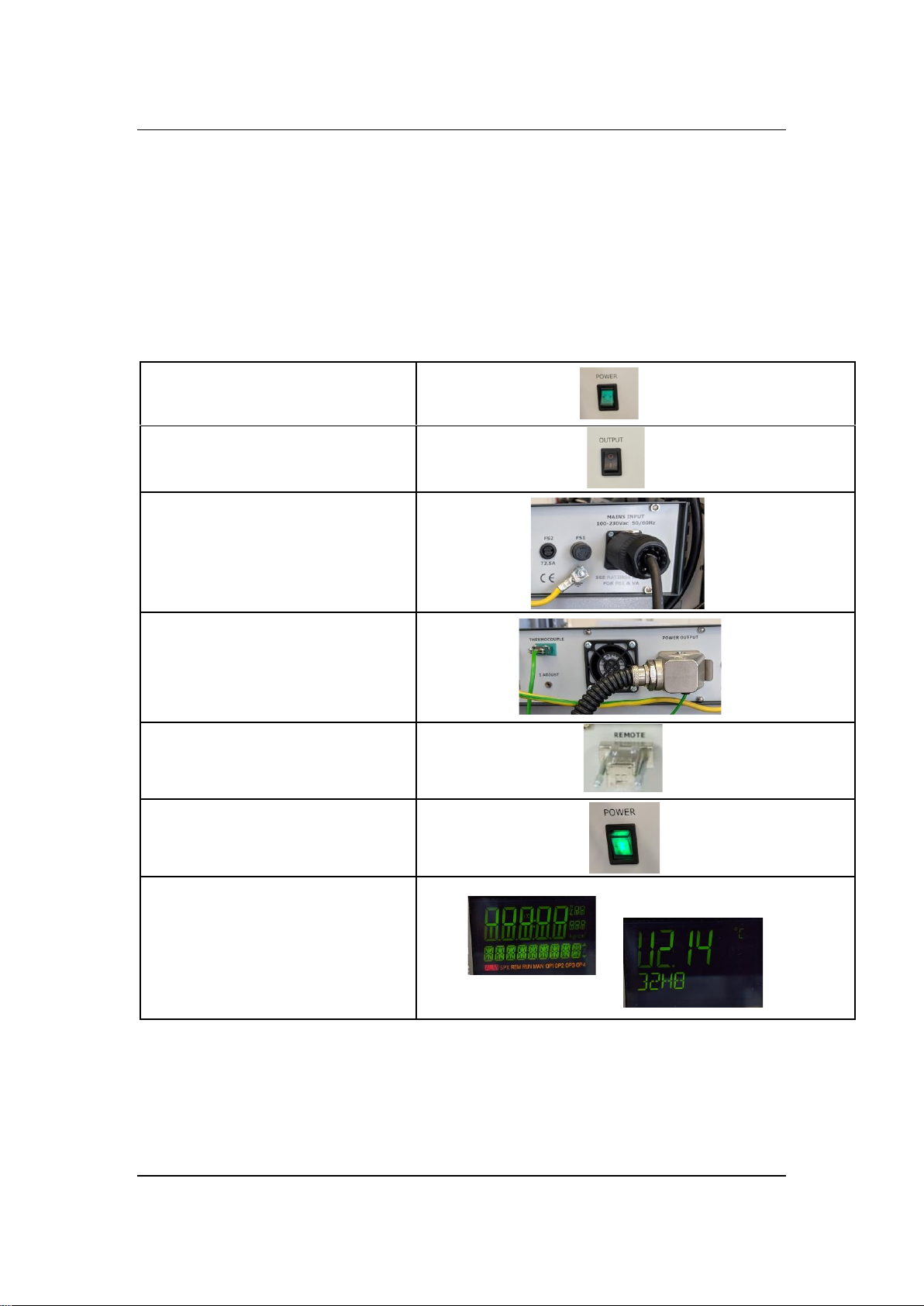
4OVERVIEW CONTROLS AND CONNECTORS ................................................................7
4.1 Front Panel Controls and Indicators .......................................................................7
4.2 Rear panel Controls and Connectors......................................................................7
4.3 Temperature Controller -Eurotherm 32h8...............................................................8
4.4 Current meter/I Adjust.............................................................................................8
4.5 Remote / Output Current & Voltage Monitor Signals..............................................8
4.6 Communications .....................................................................................................9
5OPERATION –QUICK START, CONNECT AND ON .....................................................10
5.1 Operation Quick Start –Manual Temperature control..........................................11
5.2 Operation Quick Start –Auto Temperature control ..............................................12
5.3 Operation Quick Start –Other key settings ..........................................................13
6SOFTWARE OPTIONS.....................................................................................................14
7APPENDIX A SPECIFICATIONS ...................................................................................16
8APPENDIX B MAINTENANCE & SERVICE ...................................................................17
9APPENDIX C WARRANTY & REPAIR...........................................................................18
10 APPENDIX D WIRING DIAGRAM...................................................................................19

Product Manual
Page 4 of 19 2022-10-31
1 INTENDED TO USE
The PSU-DC-XXX is only designed for use with UHV Design products, Heater Module,
ECI/ECR deposition stages and Multicentres requiring resistive heating of a sample on a
sample holder under clean UHV-conditions.
2 UNPACKING AND INSPECTION
•Visually inspect the transport packaging for signs of external damage.
•Unpack the Power Supply and accessories and retain the packaging
materials.
Note: Retain the packaging materials for later use. The PSU-DC-XXX must be
stored and transported in the original packaging material only.
•Check the package contains all the parts and accessories as shown below.
•Examine the PSU-DC-XXX for completeness and signs of damage
Should the transport packaging or any units be damaged in any way, please contact your
local sales representative.

Product Manual
Page 5 of 19 2022-10-31

Product Manual
Page 6 of 19 2022-10-31
3 INSTALLATION
The PSU-DC-XXX must be used
•Altitude below 2000 meters.
•Temperature for safe operation: 5 °C to 40 °C.
•Maximum relative humidity: 80% for temperature up to 31 °C
decreasing linearly to 50% at
40 °C.
•Power supply voltage fluctuations not to exceed ±10% of the nominal
voltage.
3.1 Mains Input Power
The DC Power Controller operates with mains voltages of 100-230Vac
50/60Hz. Input power requirement is 3.2KVA max. ensure the mains
supply is suitably rated.
3.2 Fusing
Fuse
Function
Location
Type/Rating
FS1 (230VAC+/- 10%)
Mains Input
Rear Panel
6.33x32mm ceramic,T6.3A
FS1 (100-120V)
Mains Input
Rear Panel
6.33x32mm ceramic,T12.5A
FS2
DC Power Supply
Rear Panel
5mmx20mm, glass
FS3
Output Power
Internal*
bottle fuse D02 gG
Warning: *Disconnect the mains input supply before removing the top
cover.
The cause of any repetitive fuse blowing must be investigated and
resolved.
3.3 Mains Input
Use the supplied Neutrik connector (32 Amp rating) and connect to local
mains supply via suitable mains cabling. Insert connector and twist,
ensuring lock is at the top of the connector. Minimum 3-core cable size for
230V is 0.75mm2 and for 110V is 1.5mm2. Keep cable lengths as short as
possible.
3.4 Earth Stud
A rear panel Earth Stud is provided for connection to a well bonded earth.
Use copper braid of minimum 4.0mm2.

Product Manual
Page 7 of 19 2022-10-31
4 OVERVIEW Controls and Connectors
4.1 Front Panel Controls and Indicators
4.2 Rear panel Controls and Connectors
Thermocouple Connector
(k type shown others possible)
REMOTE
Supplied plug must be fitted with pin 5-15 link
RS232
Optional for use with
iTools
I ADJUST
Current limit potentiometer
for 100% demand
POWER OUTPUT
Heater Current
MAINS INPUT
32A Neutrik connector
Protective Earth
Connection use 4mm
2

Product Manual
Page 8 of 19 2022-10-31
4.3 Temperature Controller -Eurotherm 32h8
Reference should be made to the Eurotherm short-form Operating Manual
supplied with your unit on how to gain entry to each access level and basic
operation.
Full Operator Handbook can be downloaded from Eurotherm.co.uk or
Eurotherm.com.
The ITools suite of programmes can be used for remote PC control via the
RS232 input. Refer to section 6 and the Eurotherm website.
Note: Always allow the Eurotherm 32h8 to complete its ‘start-up’
routine before operating any switches or digital inputs
4.4 Current meter/I Adjust
The front panel meter will display the current in the load from 00.0 to ~
Unit max Amps. When supplied as part of an order with a UHV Design in
vacuum heater the unit is normally current limited to just above the
maximum recommended this will be noted in the Test Data sheet.
The unit is current limited to ~ 27.0 Amps as factory default when
supplied as a free standing power supply.
4.5 Remote / Output Current & Voltage Monitor Signals
The rear panel 15-Way HD connector socket Remote functions are as
below:
Pin 1 Output I Sense +ve, 1mV/Amp
Pin 2 No Connection
Pin 3 LA, Link to Pin 8 to set Eurotherm 32h8 into ‘Standby’
(inhibit)
Pin 4 No Connection
Pin 5 Interlock: Link to Pin 15. Output will be inhibited until Pins 5
& 15 are linked
Pin 6 Output I Sense –ve
Pin 7 No Connection
Pin 8 C, Link to Pin 3 to set Eurotherm 32h8 into ‘Standby’
(Inhibit)
Pin 9 LC, Link to Pin 14 to select Second Setpoint on 32h8
Pin 10 No Connection
Pin 11 Output V Sense +ve, 1mV/Volt
Pin 12 Output V Sense -ve
Pin 13 Link to Pin 8 to set Eurotherm 32h8 into ‘Standby’ (inhibit)
mode when Output Switch is OFF
Pin 14 LB, See Pin 9
Pin 15 See Pin 5

Product Manual
Page 9 of 19 2022-10-31
The Remote connector will be supplied, as standard with Pins 5+15 linked.
Note: The Interlock link has a potential of +24V. Do not apply an
external voltage to any Pin.
Warning: The I and V Sense signals are NOT isolated from the
output.
4.6 Communications
As standard the DC Power Controller is fitted with RS232 communications.
RS485 is available to special order.
Connection to rear panel 9-way D-Type plug as below:
Pin 1 Earth
Pin 2 HF TX B(-)
Pin 3 HE RX A(+)
Pin 5 HD Common
iTools software is available from Eurotherm at several levels.

Product Manual
Page 10 of 19 2022-10-31
5 Operation – Quick Start, connect and ON
Never operate the DC Power Controller with either of the covers removed.
The DC Power Controller, is simple to operate, either from the front panel
controls, or remotely. Note that rear panel cooling fan will operate as long
as the front panel Output switch is ON. The Internal DC power module fans
will operate according to current demand.
POWER OFF
OUTPUT OFF
CONNECT MAINS AND GROUND,
CONNECT POWER OUTPUT AND
THERMOCOUPLE
Fit REMOTE plug (pin5-15 must
be linked)
POWER ON
EUROTHERM BOOT SEQUENCE

Product Manual
Page 11 of 19 2022-10-31
5.1 Operation Quick Start –Manual Temperature control
SELECT MANUAL MODE
(may already be selected)
SET DEMAND TO 0.0%
Note Lower Display circled red shows
power demand in %
OUTPUT ON
MANUALLY INCREASE
CURRENT(POWER) TO REACH
DESIRED TEMPERATURE.
Refer to equipment manual and
test data for maximum and
typical operating currents Note
there will be a time constant
between applied current and
temperature rise.
Press and hold
>1s
Cycle through
modes
Auto, Manual, Off
Press
LED ON-Green
Adjust
(example only shown)

Product Manual
Page 12 of 19 2022-10-31
5.2 Operation Quick Start –Auto Temperature control
SELECT AUTO MODE
(may already be selected)
Note The auto mode depends on
the PID settings, set ramp rate
(RR), the sample mass and
emissivity. Different temperature
ranges may require different PID
and RR settings. If the PSU is
supplied with an instrument
these have typically been set up.
SET DEMAND TO 0 DEGREES
Note Lower Display circled red shows
temperature in degrees C
OUTPUT ON
INCREASE SET TEMPERATURE
Refer to equipment manual and
test data for maximum and
typical operating currents Note
there will be a time constant
between applied current and
temperature rise.
Adjust
(example only shown)
Press and hold
>1s
Cycle through
modes
Auto, Manual, Off
LED ON-Green

Product Manual
Page 13 of 19 2022-10-31
5.3 Operation Quick Start –Other key settings
Ramp Rate (degrees C/min)
Refer to instrument manual for
typical and maximum
recommended values.
Autotune PID
1. Set to Auto Mode (see 5.2)
2. Set temperature in the range typically
required
1.Cycle through
2. Adjust
Press and hold
Press to select
Enter
)
1. Cycle to ATUNE
2. Set to ON
Eurotherm will cycle
through settings to
optimise tuning

Product Manual
Page 14 of 19 2022-10-31
6 Software options
Eurotherm provide a number of software options to connect and communicate with the
Eurotherm module. via the rear panel RS232 connector. Please refer to the Eurotherm
QuickStart guide and website for full details and downloads.
Eurother iTools
1. iTools WIZARD (free download)
Allows modification of the Eurotherm module configuration settings such as ramp rate and
process time, this can be simpler than using the front panel buttons. These configurations can
be saved and up/downloaded. Note be cautious of changing settings as it can have
unintended consequences. It is recommend that the as supplied configuration is saved as a
back-up, before any changes are made.
Example screen shots

Product Manual
Page 15 of 19 2022-10-31
2. iTools Engineering Studio (free download)
Allows direct control and emulated viewing of the Eurotherm module panel
Example screen shots
3. iTools Programmer Editor (cost option)
Refer to Eurotherm for more details

Product Manual
Page 16 of 19 2022-10-31
7 Appendix A Specifications
Input Mains Voltage 100-230Vac, 50/60Hz
Output Power 60V @ 50Amps DC, min ~5 watts
Power Consumption 3.2KVA Max
Fusing: Rear Panel FS1: T6.3A (230V+/-10%)
T12.5A (100-120V)
Ceramic 6.3mmx32mm
FS3 T2.5A
Glass 5x20mm
Internal FS4 35A D02 Bottle, gG
Temperature Controller:-
Type Eurotherm 32h8
Sensor Types K or N or E, others as options
Sensor Ranges 0oC to + 1000oC (Default)
For others, consult Eurotherm handbook
Control Mode PID, ON/OFF
Ramp Rate OFF ,0.1 to 3000 degrees/minute
Digital Inputs DI1 Standby (OFF) Default
DI2 SP2 Default
Others available-see Eurotherm Handbook
Tuning One-shot self-tune algorithm
Sensor Fail Output OFF
Communications RS232 (standard), RS485 (option)
Environmental-
Operating Temp +5oC to +40oC; Storage 10oC to +70oC
Relative Humidity 5% to 85% RH
General Electrically conductive pollution to be excluded
from the cabinet. Not suitable for use above
2000m or in explosive or corrosive
atmospheres.
Dimensions-
Height 2U, 89mm, nom
Width Full rack mounting
Depth 520mm, excluding mating connectors
Weight 14kg
EMC and Safety Standards - Compliant with relevant EU directives
BS EN 61000-6-4: 2007, BS EN 61000-6-3:2007, BS EN 61010-1: 2010
RoHS Compliant
PAT Tested for Class II Equipment

Product Manual
Page 17 of 19 2022-10-31
8 Appendix B Maintenance & Service
The DC Power Controller is designed as a reliable and robust unit and should not
require any regular maintenance.
Servicing must only be carried out by qualified personnel
The front panel power switch should not be relied upon to provide adequate
isolation from the mains supply for servicing or maintenance purposes.
Use only specified fuses.
All external cabling must be maintained in good condition and replace if damaged.
In order to maintain compliance with relevant EU directives, only use exact
replacement parts when servicing; these must have the same specifications and
ratings as the original components. Spares can be purchased from UHV Design
Ltd.

Product Manual
Page 18 of 19 2022-10-31
9 Appendix C Warranty & Repair
Warranty
1. Subject to fair wear and tear and the due observance of any installation use,
storage, operating or maintenance instructions, the Seller undertakes to replace
or, at its option repair free of charge to the purchaser, any goods which the
purchaser can establish are faulty by reason of defective workmanship or
materials which are returned to the Seller, carriage paid, within 12 months of the
date of dispatch by the Seller. In the event, however, that the Seller supplies
spare parts either direct, or that are fitted or installed or replaced by the Sellers'
service center such spare parts will be subject to a warranty period of six months
only.
2. The Purchaser cannot return any product for warranty repair without the prior
approval of UHV Design Ltd. All returned products must be clearly identified on
the outside of the packaging and be accompanied by contact details and a fault
report.
Where appropriate, the Customers should, in the first instance, contact the local
selling agent.
3. We reserve the right to decline to service any equipment we consider is in any
way hazardous, either by transit damage, modification or contamination.
Repair
The following additional terms and conditions apply in the event that the
customer, elects to use the services of Sabre Controls Ltd workshop on a
chargeable basis.
1. At its own cost the customer shall dispatch the equipment to the workshop,
carriage paid, suitably packaged, protected and insured, accompanied by
documentation stating Company, contact details and a fault report. Please state
clearly any budgetary limit on repair costs.
2. During the period that the equipment is on UHV Design’s premises, the
equipment shall be insured against all risks.
3. UHV Design Ltd will provide an acknowledgement of the receipt together with
an estimate of the repair charges. Such estimates are carried out on a visual
basis and are therefore intended as a guide only. Formal fixed price repair
quotations are available and involve the disassembly of the equipment to
determine the full extent of any work necessary to restore the equipment to an
acceptable standard. In the event that the customer chooses not to proceed with
the repair UHV Design Ltd will make a charge to cover this examination effort.

PSU-DC MANUAL Rev 3.0 31/10/22
10 Appendix D Wiring Diagram PSU-DC-48V-62A
This manual suits for next models
7
Table of contents
Popular Power Supply manuals by other brands

Pepperl+Fuchs
Pepperl+Fuchs HiD2025 manual

Gewiss
Gewiss Chorus GW 10 460 quick start guide

Matsusada Precision
Matsusada Precision R4K-80 Series instruction manual

Lambda
Lambda Sirius 250 instruction manual

CREATIVE ELECTRONICS
CREATIVE ELECTRONICS SMC-3303X Operation manual

Horizont
Horizont farmer AS50 instruction manual