manuals.online logo
Brands
  1. Home
  2. •
  3. Brands
  4. •
  5. Ultra Beam
  6. •
  7. Antenna
  8. •
  9. Ultra Beam UB20-MX User manual

Ultra Beam UB20-MX User manual

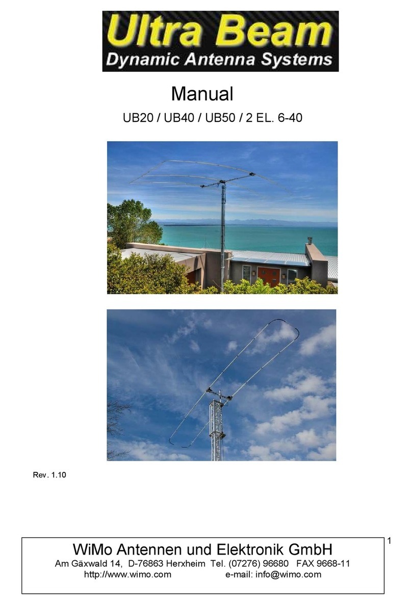
MANUAL
UB20 / UB40 / UB50 / 2 EL. 6-40
!1
Rev. 1.10
!2
INTRODUCTION
Some UltraBeam models work in 30 and 40 meters with folded elements, this allows you to work!
30 and 40 meters with full-size elements in the same size 6-20 models.!
This technique is applied on 2 and 3 element Yagi models.!
On these two models curves are applied to the ends of the elements, joined together by !
fiber glass tubes, this creates a corridor in which the copper tape can scroll to reach the required!
length to resonate up to 40 meters.!
Figures 1 and 2 show in red the path and the shape of a "C" that the folded dipole assumes when
operating on 40 meters.
!
NOTE: This manual only refers to the installation of the curves, side elements!
and other specific parts of the models who work in 30 and 40 with folded elements.!
For all other antenna assembly instructions refer to the manual "Standard"
5,4 m.
1,6 m. 5,1 m.
Percorso nastro!
rame berillio
Fig.1 Fig.2
Director Driver Director Driver1 Driver2
2 elementi!
6-40
UB-50
Driver!
6-40
Driver!
30-40
Modello mono driver
Modello doppio driver
PVC GUIDE TUBES DRIVER 30-40
!
All UltraBeam models working in 30 and 40 meters with folded elements include!
the installation of internal guide pct tubes to the left and right elements connected to the motor
unit.
!3
The guide tube of folded elements is essential to allow the tape to slide within the!
curve and the side elements without bending.!
The guide element is composed of two sections of PVC pipe (2 x 1500) total length 3 meters.!
Connect the two sections with PVC joining and tape with common insulating tape.!
Insert a second junction to one of the two ends, this will subsequently be used to!
connect the guide tube to the motor unit (Fig.1-2)!
Insert the guide tube into the previously prepared element (Figure 3)
MOTORE
pvc guide tube
Fig.1 Fig.2 Fig.3
elemento telescopico
"
!4
INSTALLATION OF ELEMENTS ON MOTOR UNIT
Before inserting the elements in the motor unit it is necessary to fix the PVC guide tube.!
During this operation it is necessary that the element remains aligned to the engine, if your!
set-up assembly does not allow this, it is absolutely needed the help of a second person to
support the element during the insertion of the guide tube.!
The inner PVC tube to be inserted to the engine contains a bi-adhesive applied during the
construction phase that will keep the junction steady in time (fig.4)!
Push the PVC pipe until it reaches its maximum insertion (Figure 1)!
Place the element in the motor unit until it stops (Fig.2-3) and tighten the clamp of the
rubber cap.
Fig.1 Fig.2 Fig.3
!
Important note:!
you must carefully mounting the guide tubes.!
In case of possible detachment of even a single tube, the copper tape will bend inevitably!
compromising the unit's motor functions.……..
Fig.4
Bi-adhesive
NOTE:!
The procedures relating to the installation of guide tubes!
are common to all models with folded elements. !
- 2 EL. 6-40!
- UB-20!
- UB-40!
- UB-50
"
!5
CURVES ASSEMBLY AND SIDE TUBES
tubo laterale!
1 x 800 mm.
tubi laterali!
3 x 1400 mm.
curve
giunto
“ T ”
2 elementi 6-40
UB-50
come sopra come sopra
Only after inserting all the elements to the motor units you can install the curves and the
lateral elements.!
!
For the side elements glass fiber tubes of diameter 20mm are employed!
The 6-40 2 elements uses a single tube of 800 mm between a curve and the other.!
The UB-50 employs three pipes of 1,400 mm. joined together by two fiber joints for a total length of!
4200 mm.!
In both cases, all the curves and tubes joints are fixed by means of thermo-tightening sheaths with!
high mechanical resistance with internal adhesive, which guarantee solid, permanent and!
waterproof junctions!
On the UB50 a "T" mechanically connects the end of the central element to the side elements, in!
this way the weight of the entire lateral element will be distributed on all three elements.
2 ELEMENTS YAGI 6-40!
UB-50 YAGI!
!
!
"
!6
To apply the thermo shrinking a heat gun is needed (1500-2000W)!
The heating time varies depending on the outside temperature, and in any case the correct
temperature is reached when the inner glue comes out, creating a ring all around the edges.!
Insert the side tube and the ends of the elements in the curves up to the maximum insertion, (fig, 1)
before heating the sheaths check that the side section is parallel to the boom, to avoid typical!
candy shape.!
Move the sleeves exactly to the center of the splice and heat as described above. (Fig.2)
!
!
!
NOTE: Clean the joint surfaces of the tubes and curves before applying the sheath.!
Avoid any twisting and movement of the joint until it is completely cool!
The curves have drain holes, make sure they are facing down (picture 3)
Fig.1! ! ! ! Fig.2 Fig.3
The procedures of the curves junctions are identical to the elements 2, only difference is the length!
of the side element that is longer and is formed by three segments, in addition to a T central support Fig.4!
fiberglass tube!
3 x 1400 mm.
joint tube!
2 x 100 mm.
curve!!!!! !!!! !curve!
Before joining the three elements with joints you must insert the "T" shaped support.!
Slide the T inside the element that will be placed at the center, no need to fix it, it will align to the central
element of the antenna at the end of assembly
T
Fig.4
FIXING / ADJUSTMENT OF “T” SUPPORT
!
………………………………………………………………………………………...!
!
Insert the T shaped tube to the end of the antenna central element.!
The tube has sufficient length to slide the element inside, this allows a!
telescopic adjustment in the direction of the arrows, useful to set the correct position of the T so
that the whole side panel stays perfectly lined up (only aesthetic factor) any not perfect!
alignment will not compromise in any way the antenna operation.!
Once the exact spot is found, apply the heat shrink sleeve to lock the T-tube to the end!
of the telescopic element.!
Move laterally the T inserted into the side panel in the sense of <arrows> to adjust!
parallelism between the antenna elements, it is not necessary to lock the T element, you can also!
leave it free to slide, so it will always find its natural position."
!7
Fig.4 Fig.5 Fig.6 Fig.7
Combine the 1400 mm. pipes placing the 10 cm small tubes exactly at half junction (fig.4-5)!
Slide the sleeves on joints and heat up to the correct temperature (Figure 6)!
Drill a small 2-3 mm. hole on the same axis in the center in both junctions (fig.7)
!
!
NOTE: important to check that the holes are facing down before heating conduits that hold whole side
element to the curves
Regolare nel senso delle!
frecce per allineare
l’elemento laterale prima di
fissare la giunzione
regolare nel senso delle!
frecce affinché
l’elemento centrale sia
pararrello agli elementi
esterni
UB20-MX / UB40-MX"
!8
The models UB20 and UB40 differ from UB50 MX for the size of the elements and boom and why
they work in a configuration 2 elements moxon on the lower frequency.!
With regard to the assembly instructions of the curves and side elements, they are absolutely!
identical to those of UB50 described in this manual.!
On these two models the PVC guide tubes will be installed on both the external antenna
elements. !
The figures show the copper tape path that allows the two antennas to act as a 2 elements
moxon configuration on the lowest frequency at which the model works.
UB20-MX
UB40-MX
Director Driver1 Driver2 Director Driver1 Driver2
2 elements moxon when work on 20 meter!
!
2 elements moxon when work on 40 meters!
!
TUBI LATERALI / TUBI GUIDA!
!
!
NOTA: le quantità indicate nella tabella si intendono per un solo lato antenna (pag.5)!
"
MODEL
LENGTH TELESCOPIC ELEMENTS
2 EL. 6-40
5,4 m.
UB20-MX
3,5 m.
UB40MX
7,4 m.
UB-50
5,4 m.
!9
TELESCOPIC ELEMENTS
MODEL
LATERAL TUBES LENGTH
PVC TUBES LENGTH
2 EL. 6-40
1 x 0,8 m.
2 x 1,5 = 3 m.
UB20-MX
2 x 1,15 = 2,3 m.
1 x 1,5 m
UB40-MX
3 x 1,5 = 4,5 m.
2 x 1,5 = 3 m.
UB-50
3 x 1,4 = 4,2 m.
2 x 1,5 = 3 m.
pvc tube
telescopic element
lateral elements
ANTENNAS DIAGRAM
2 ELEMENTI 6-40
!10
1,62 m.
The position of the Mast / Boom plate in!
models with 3 elements is always at the
center boom, !
in cases where it is necessary you can
move it toward the director,this will
provide more space between!
the central element and Mast!
!
Description on page 6 of the Standard
manual
1 x 162 cm !
Sez. 60 x 60 !
159 cm 124 cm
!11
269 cm 231 cm
289 cm!!!!!!!242 cm
Nota : !
UB20 - UB50 - UB40 are models with double driver, download the manual “Switch”

This manual suits for next models

3

Other Ultra Beam Antenna manuals

Ultra Beam UB640-VL2.3 User manual

Ultra Beam

Ultra Beam UB640-VL2.3 User manual

Ultra Beam UB20 User manual

Ultra Beam

Ultra Beam UB20 User manual

Popular Antenna manuals by other brands

DESHIBO GA-450 manual

DESHIBO

DESHIBO GA-450 manual

Siro CB 27 U installation manual

Siro

Siro CB 27 U installation manual

Ubiquiti airMAX Omni AMO-2G10 quick start guide

Ubiquiti

Ubiquiti airMAX Omni AMO-2G10 quick start guide

Fracarro TAU11 quick start guide

Fracarro

Fracarro TAU11 quick start guide

COBHAM Sea Tel 6011-4 installation manual

COBHAM

COBHAM Sea Tel 6011-4 installation manual

Velleman ANTDVBT7 user manual

Velleman

Velleman ANTDVBT7 user manual

Buffalo WLE-NDR Quick setup guide

Buffalo

Buffalo WLE-NDR Quick setup guide

l-com HG2415Y installation instructions

l-com

l-com HG2415Y installation instructions

Lancom AirLancer Extender O-9a installation instructions

Lancom

Lancom AirLancer Extender O-9a installation instructions

Globalstar Sat-Fi2 Quick installation guide

Globalstar

Globalstar Sat-Fi2 Quick installation guide

COBHAM Sea Tel installation manual

COBHAM

COBHAM Sea Tel installation manual

Monster KATANA METRO user manual

Monster

Monster KATANA METRO user manual

Solarcon A-99 Assembly instructions nstructions / owners manual

Solarcon

Solarcon A-99 Assembly instructions nstructions / owners manual

MikroTik RouterBOARD Installation Guide and Warranty Information

MikroTik

MikroTik RouterBOARD Installation Guide and Warranty Information

Panorama Antennas DMM4-6-60 installation instructions

Panorama Antennas

Panorama Antennas DMM4-6-60 installation instructions

DELTALINK ANT- 6033N Assembly guide

DELTALINK

DELTALINK ANT- 6033N Assembly guide

Shure UA845 user guide

Shure

Shure UA845 user guide

Ventev M6050060D37202WST quick guide

Ventev

Ventev M6050060D37202WST quick guide

manuals.online logo
manuals.online logoBrands
  • About & Mission
  • Contact us
  • Privacy Policy
  • Terms and Conditions

Copyright 2025 Manuals.Online. All Rights Reserved.