Ultra electronics HYPERSPIKE HS-14 User manual

OPERATION AND MAINTENANCE MANUAL
HYPERSPIKE®MODEL HS-14 RAHD


HyperSpike® HS-14 RAHD Operation and Maintenance Manual
Copyright © "RSB Group", Moscow, Krzhizhanovskogo str., 14/2
90169A-MAN-HS14RAHD
REV A
i
TABLE OF CONTENTS
Contents
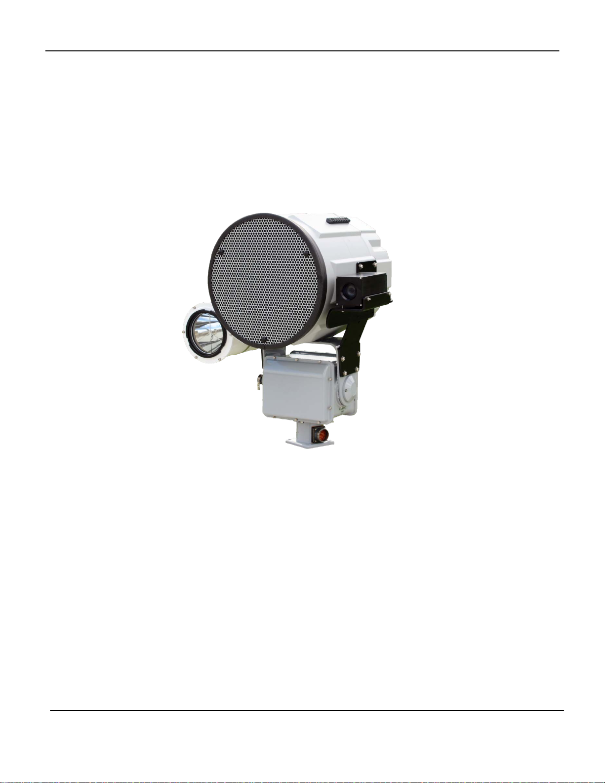
1. Hardware..................................................................................................................................1
1.1. Hardware ...........................................................................................................................1
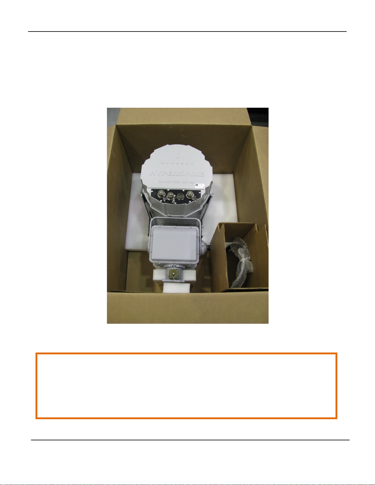
1.2. Included in Box ..................................................................................................................2
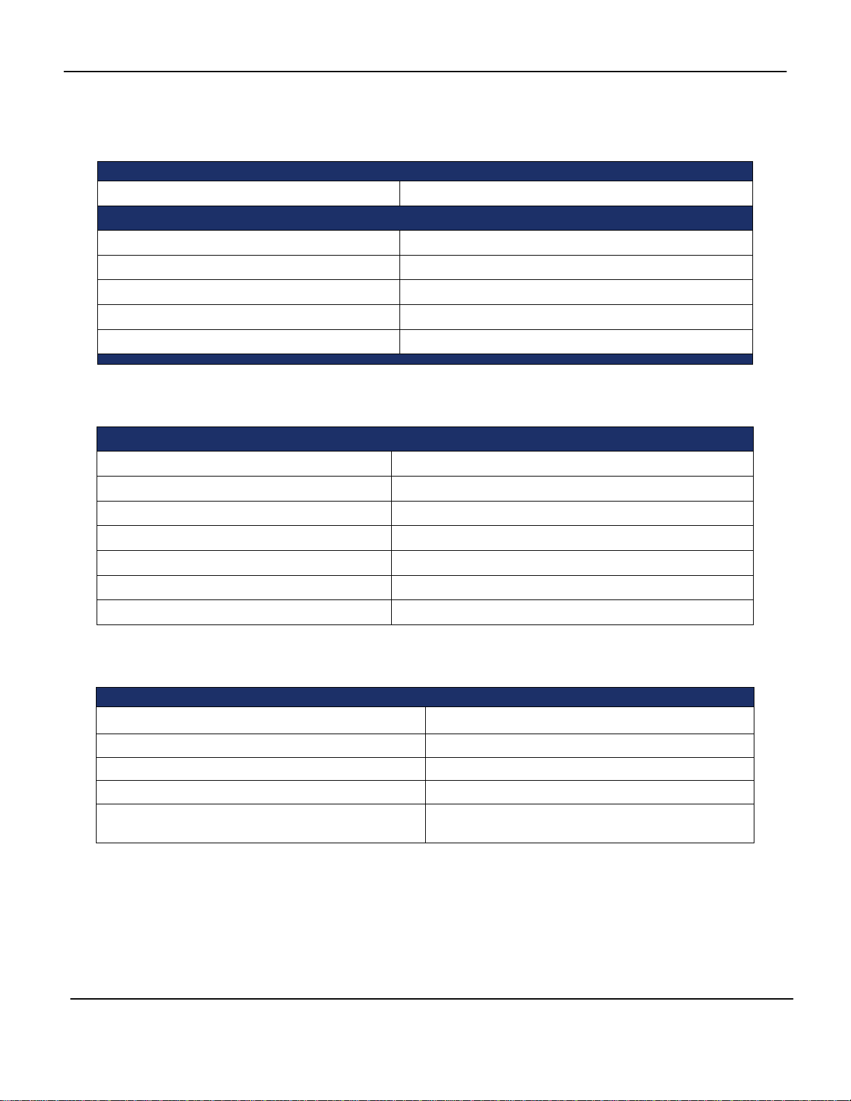
2. Hardware Specifications...........................................................................................................3
2.1. Physical Characteristics.....................................................................................................3
2.2. Electrical Specifications .....................................................................................................3
2.3. Acoustic Specifications......................................................................................................3
3. RAHD and Electronics Assembly Setup...................................................................................4
3.1. RAHD Installation and Mounting........................................................................................4
3.2. System Wiring....................................................................................................................6
3.2.1. Connection #1: Interconnect Cable ..........................................................................7
3.2.2. Connection #2: Power/Data Cable ...........................................................................7
3.3. Wiring Diagram for 110 VAC Installation- With Transformer..............................................8
3.4. Wiring Diagram for 220 VAC Installation- With Transformer..............................................9
3.5. Connection #3 Auxiliary Connections (optional).................................................................9
4. Networking and Device Setup ................................................................................................10
4.1. Initial Setup......................................................................................................................10
5. Controls and Operations.........................................................................................................11
5.1. First Time Setup...............................................................................................................11
5.2. Login Page.......................................................................................................................12
5.3. Simultaneously Controlling Multiple RAHDs ....................................................................13
5.4. Removing a Device..........................................................................................................15
5.5. Volume Panel...................................................................................................................16
5.6. Pre-Recorded Tracks.......................................................................................................16
5.6.1. Uploading Audio Files.............................................................................................17
5.6.2. Stopping a Playing Track........................................................................................17
5.6.3. Editing or Deleting a Track .....................................................................................18
5.7. Live Microphone...............................................................................................................18
5.8. Points of Interest (POI) ....................................................................................................19
5.9. Tours................................................................................................................................21
5.10.Dead Zones....................................................................................................................25
5.11.Pan/Tilt Control...............................................................................................................27
5.12.All/Select Mode...............................................................................................................28
5.13.Account Options and Logout ..........................................................................................29
5.14.Factory Reset.................................................................................................................30
6. Preventative Maintenance and Cleaning................................................................................31
6.1. Ground Operations and Sandy Environments..................................................................32
6.2. Salt Water Environments.................................................................................................32
6.3. To prepare for storage.....................................................................................................32
7. Troubleshooting......................................................................................................................32
7.1. Inspect incoming Power and Data to the HS-14 RAHD...................................................32
7.2. Testing for Network Connectivity .....................................................................................33
7.3. Troubleshooting Software................................................................................................33
8. WARRANTY...........................................................................................................................34
8.1. Failures Not Covered by This Warranty...........................................................................35

HyperSpike® HS-14 RAHD Operation and Maintenance Manual
Copyright © "RSB Group", Moscow, Krzhizhanovskogo str., 14/2
90169A-MAN-HS14RAHD
Rev A
ii
8.2. Limitation of Implied Warranties.......................................................................................35
8.3. Exclusion of Certain Damages.........................................................................................35

HyperSpike® HS-14 RAHD Operation and Maintenance Manual
Copyright © "RSB Group", Moscow, Krzhizhanovskogo str., 14/2
90169A-MAN-HS14RAHD
Rev A
iii
SAFETY PRECAUTIONS
The HyperSpike®HS-14 RAHD uses high operating voltages and sound levels. The primary safety
risks are: 1) electrical shock and 2) hearing damage or loss. Only properly trained personnel should
operate the HS-14 RAHD and abide by the critical safety warnings identified in this manual to
prevent injury or death during operation.
Additional Electrical Safety Measures
Following these basic safety measures will prevent dangerous or potentially deadly situations from
arising :
•Inspect the power cable for damage before each use.
•Keep the power cable away from heated surfaces.
•Never remove the power cable from an outlet by pulling on the cord.
•Never override any of the HS-14 RAHD’s electrical safety features.
Sound Safety Measures
The National Institute for Occupational Safety and Health (NIOSH) recognizes 120 dB as the
threshold of pain for unprotected hearing. Operators should wear hearing protection and ensure
that personnel are not directly in front of the device, at close range, when the power is ON.
WARNING:
LIFE THREATENING ELECTRIC SHOCK OR DEATH BY ELECTROCUTION
100 - 250 VAC IS PRESENT WHEN ENERGIZED
Always plug the unit into properly grounded electrical outlets.
Never allow any part of the system to sit in pooled water, or to be immersed in water.
Do not operate the device if the power cable is pinched, frayed, or cut.
WARNING:
TEMPORARY OR PERMANENT HEARING DAMAGE MAY OCCUR
HIGH LEVEL OF SOUND CAN BE EMITTED
Always wear hearing protection according to OSHA’s hearing conservation program.
Operators must remain behind the HS-14 RAHD during operation.

HyperSpike® HS-14 RAHD Operation and Maintenance Manual
Copyright © "RSB Group", Moscow, Krzhizhanovskogo str., 14/2
90169A-MAN-HS14RAHD
Rev A
1
1. Hardware
1.1.Hardware
The HyperSpike®HS-14 RAHD (Remote Acoustic Hailing Device) is designed for ease of
assembly. It is suitable for both static and mobile applications. The RAHD unit can be
equipped with optional accessories including but not limited to cameras, spotlights, and laser
dazzlers per customer requirements.
Figure 1.1-1 HS-14 RAHD
Note: Full physical, electrical and acoustic specifications are contained in Section 2.

HyperSpike® HS-14 RAHD Operation and Maintenance Manual
Copyright © "RSB Group", Moscow, Krzhizhanovskogo str., 14/2
90169A-MAN-HS14RAHD
Rev A
2
1.2.Included in Box
Included Items are:
1x HS-14 RAHD Assembly, P/N 90169A-801-XX
1x Power/Data Cable, P/N 42222A-801
1x Interconnect Cable, P/N 42206A-801
Figure 1.2-1 HS-14 RAHD – In Packaging
CAUTION:
The HS-14 RAHD ASSEMBLY IS A MINIMUM TWO PERSON LIFT
HEAVY OBJECT - OVER 50 lbs
Straps connected to the mounting bracket and pan/tilt base may be used to assist lifting

HyperSpike® HS-14 RAHD Operation and Maintenance Manual
Copyright © "RSB Group", Moscow, Krzhizhanovskogo str., 14/2
90169A-MAN-HS14RAHD
Rev A
3
2. Hardware Specifications
2.1.Physical Characteristics
2.2.Electrical Specifications
HS-14 RAHD ELECTRICAL SPECIFICATIONS
Power Input
100-130 VAC, 200-250 VAC with Transformer
Frequency
50/60 Hz
Typical Current Draw, Normal Voice 2.4 Amps, 120 V
Typical Current Draw, Maximum Tone
4.0 Amps, 120 V
Auxiliary Power Output
12 VDC, 24VDC
Output Current -12 VDC Aux. Supply Fused at 1 A, shared by connectors A, B, D
Output Current- 24 VDC Aux. Supply
Fused at 7.5 A, shared by connectors A, B, D
2.3.Acoustic Specifications
HS-14 RAHD WEIGHT
Complete System
83.6 lbs (37.9 kg)
HS-14 RAHD DIMENSIONS
System Width
15.4 in (39.1 cm)
System Height 27.1 in (68.8 cm)
System Depth
18.6 in (47.2 cm)
Front Wind Load Area
260 in2 (1677 cm2)
Side Wind Load Area 350 in
2
(2258 cm
2
)
HS-14 RAHD ACOUSTIC PERFORMANCE
Beam Width +/- 12° (24° conical @ 2 kHz /-3 dB)
Communication Range
Up to 1500 m
Frequency Response
300 Hz - 8 kHz
Sound Pressure Level, Peak, A-Weighted
148 dB @ 1 meter
Speech Transmission Index (STI-
Intelligibility)
0.81 out of 1.00

HyperSpike® HS-14 RAHD Operation and Maintenance Manual
Copyright © "RSB Group", Moscow, Krzhizhanovskogo str., 14/2
90169A-MAN-HS14RAHD
Rev A
4
3. RAHD and Electronics Assembly Setup
3.1.RAHD Installation and Mounting
Secure the Sound Emitting Assembly and transformer box (if equipped) to a stable surface.
To maximize water protection, the recommended orientation of the transformer box is with
connectors facing down. Refer to mounting details in Figure 3.1-2 and Figure 3.1-3. Figure
1.1-1
Ensure that mounting locations account for the cable length available. The standard length
of cable between the emitter and transformer box is 5 feet. Optional lengths are available at
customer request.
Figure 3.1-1 Sound Emitting Assembly and Transformer BoxFigure

HyperSpike® HS-14 RAHD Operation and Maintenance Manual
Copyright © "RSB Group", Moscow, Krzhizhanovskogo str., 14/2
90169A-MAN-HS14RAHD
Rev A
5
Figure 3.1-2 HS-14 RAHD Interface Mounting Dimensions
Figure 3.1-3 Transformer Box Interface Mounting Dimensions

HyperSpike® HS-14 RAHD Operation and Maintenance Manual
Copyright © "RSB Group", Moscow, Krzhizhanovskogo str., 14/2
90169A-MAN-HS14RAHD
Rev A
6
3.2.System Wiring
There are six sealed, weather resistant, connectors on the HS-14 RAHD, and one connector
on the transformer enclosure. Three of these connectors are designed to interface with
search lights, cameras, laser dazzlers, and other auxiliary devices. Contact Ultra
Electronics- USSI if you are interested in connecting an auxiliary device other than a
standard accessory to the HS-14 RAHD. We will work with you to ensure a smooth
integration of your accessory devices.
For proper operation, only use the connectors in accordance with the following list of
designated purposes.
Connector A – Camera/Auxiliary
Connector B – Auxiliary
Connector C – Pan/Tilt Out
Connector D – Searchlight/Auxiliary
Connector E – Pan/Tilt In
Connector F – Power/Data
Connector G – Ethernet In
Connector H– Power In
WARNING:
AC INPUT POWER MUST BE DISCONNECTED OR REMOVED FROM THE SYSTEM
PRIOR TO CONNECTING OR DISCONNECTING ANY CABLES
Figure 3.2-1 Connector Diagram

HyperSpike® HS-14 RAHD Operation and Maintenance Manual
Copyright © "RSB Group", Moscow, Krzhizhanovskogo str., 14/2
90169A-MAN-HS14RAHD
Rev A
7
To wire your HS-14 RAHD for operation, refer to the following wiring instructions:
3.2.1.Connection #1: Interconnect Cable
Connect the Interconnect Cable, P/N 42206A-801, from connector C to connector E.
This cable passes data and AC power to the Emitter’s electronics housing. Tighten each
end of the cable firmly to ensure a weather tight seal.
3.2.2.Connection #2: Power/Data Cable
Connect the Power/Data Cable, P/N 42222A-801, to connector F. Tighten the cable
firmly to ensure a weather tight seal.
While the HS-14 RAHD is designed for direct operation on a 20 Amp, 110 VAC circuit, a
step-down transformer is available for locations that have only 220 VAC. An isolation
transformer is also available for locations with non-standard or unreliable AC power.
Follow the wiring diagrams provide below to properly wire your HS-14 RAHD’s
Power/Data Cable.
Figure 3.2-2 Wiring Diagram for 110 VAC- No Transformer
Wiring Color Chart - Power/Data Cable P/N 42222A-801
Brown
110VAC Hot
Orange
110VAC Hot
Gray
110VAC Neutral
Green 110VAC Neutral
Black Ground
Red
Ground
White
Ground
Blue
Ground
Ethernet Cable Network

HyperSpike® HS-14 RAHD Operation and Maintenance Manual
Copyright © "RSB Group", Moscow, Krzhizhanovskogo str., 14/2
90169A-MAN-HS14RAHD
Rev A
8
3.3.Wiring Diagram for 110 VAC Installation- With Transformer

HyperSpike® HS-14 RAHD Operation and Maintenance Manual
Copyright © "RSB Group", Moscow, Krzhizhanovskogo str., 14/2
90169A-MAN-HS14RAHD
Rev A
9
3.4.Wiring Diagram for 220 VAC Installation- With Transformer
3.5.Connection #3 Auxiliary Connections (optional)
Accessories such as search lights, laser dazzlers and cameras can be powered and controlled
via connectors A, B, and D. Some accessories require unique interfaces with the HS-14 RAHD;
therefore, please connect your accessories according to the following recommendations.
Accessory
Assigned Connector
Daytime Camera
A
Searchlight
D
Other Accessories
B
If accessory connectors are to be used in permanent installations, weather sealing caps can be
removed by cutting the chain. This is recommended to avoid snags and impacts that could
damage the housing or nearby connectors.

HyperSpike® HS-14 RAHD Operation and Maintenance Manual
Copyright © "RSB Group", Moscow, Krzhizhanovskogo str., 14/2
90169A-MAN-HS14RAHD
Rev A
10
4. Networking and Device Setup
The HS-14 RAHD is designed to be controlled over a TCP/IP based network equipped with a
DHCP server. When powered on, the HS-14 RAHD should receive an IP address from the
network’s DHCP server. Take note of the IP address assigned to your HS-14 RAHD. You will
need this information to set up the device. If you do not know how to identify the IP address of
your HS-14 RAHD, consult your network manager.
4.1.Initial Setup
The HS-14 RAHD is designed to be operated through the use of its built in web based
Command and Control Interface (CCI).
To access this interface:
•Power on your access device (Desktop or Laptop Computer)
•Open the web browser* on your access device
•Enter the IP address of your HS-14 RAHD into the URL entry field in the same fashion
you would type in the name of any other website.
*While the Command and Control Software is supported on most desktops, laptops, and mobile
devices, it is recommended that your access device have the latest version of the Google
Chrome Browser installed. Other browsers may not be fully compatible with the CCI. To learn
more about Chrome Browser, go to https://www.google.com/chrome/

HyperSpike® HS-14 RAHD Operation and Maintenance Manual
Copyright © "RSB Group", Moscow, Krzhizhanovskogo str., 14/2
90169A-MAN-HS14RAHD
Rev A
11
5. Controls and Operations
The following subsections will guide you through the use of the HS-14 RAHD’s Command
and Control Interface (CCI). While all necessary user functions are readily accessible
through the CCI, if a user desires to write custom control software, a Software Development
Kit (SDK) is also available.
Figure 5-1 Command and Control Home Page
5.1. First Time Setup
When connecting to an HS-14 RAHD for the first time, the “Setup” Popup window will be
presented. To configure the device, enter an identifying name for your HS-14 RAHD in the
“Device Name” field, a username in the “Username” field, and a password in the “password”
field. The Command and Control Interface is configured to operate with only one user account.
If desired, the password can be changed at a later time.
Unique Device Name

HyperSpike® HS-14 RAHD Operation and Maintenance Manual
Copyright © "RSB Group", Moscow, Krzhizhanovskogo str., 14/2
90169A-MAN-HS14RAHD
Rev A
12
Figure 5.1-1 Device Setup
Click on the blue “Setup” button to continue to the login screen. Once one HS-14 RAHD has
been configured, follow the procedure listed in section 5.3 to setup any additional HS-14
RAHDs.
5.2.Login Page
After initial setup, or after connecting to the IP address of the HS-14 RAHD through your web
browser, enter your username and password in the text fields of the popup window.
Remember this USERNAME and PASSWORD as they will be needed the next time that you
need to login again.
Figure 5.2-1 Login Page

HyperSpike® HS-14 RAHD Operation and Maintenance Manual
Copyright © "RSB Group", Moscow, Krzhizhanovskogo str., 14/2
90169A-MAN-HS14RAHD
Rev A
13
If login was completed successfully, the CCI Home Page will be presented.
If the username or password is forgotten, click on “Forgot Password?” to initiate the reset
process. In the text boxes, enter the following information:
Reset Token- The full serial number of the device. Ex. RAHDHS14XXXXXX.
The serial number is listed on the white label placed on the back
of the system.
New Username- If you’d like to reset the master username, enter it here.
New Password- The new password for the device.
Confirm Password- The new password for the device.
Figure 5.2-2 Forgot Password Page
5.3.Simultaneously Controlling Multiple RAHDs
The CCI is designed to allow the user to control multiple acoustic hailing devices
simultaneously. When multiple devices are detected, the user has the ability to send
commands to an entire fleet of RAHDs at the push of a button. To add a second RAHD to
the Home Page, select the “+” button in the top right corner of the page.

HyperSpike® HS-14 RAHD Operation and Maintenance Manual
Copyright © "RSB Group", Moscow, Krzhizhanovskogo str., 14/2
90169A-MAN-HS14RAHD
Rev A
14
Figure 5.3-1 Add Device “+” Button
Enter the IP address of the device you would like to add in the “IP Address/Hostname” field,
and enter an identifying name for the device in the “Name” field. If you don’t know the IP
address of the device, consult your network manager. If the device has not already been
configured, the CCI will automatically copy the master Username and Password to it. After
completing this step for every HS-14 RAHD on your network, all of the devices will share a
common username and password.
Figure 5.3-2 Add Device Popup Window
Once IP Address and Name information is supplied, the new device should appear on the
Home Screen. After appearing on the screen, inspect the color of the “Status” indicator next
to the Device Name.
The three color codes for the status indicator are as follows:
- Green – All systems functional
- Red –Connection not established
- Orange – System fault

HyperSpike® HS-14 RAHD Operation and Maintenance Manual
Copyright © "RSB Group", Moscow, Krzhizhanovskogo str., 14/2
90169A-MAN-HS14RAHD
Rev A
15
Figure 5.3-3 Multiple Connected Devices
After adding a new HS-14 RAHD, inspect the Status Indicator. If it is not green, refresh your
browser page. If the indicator remains red, refer to Section 7- Troubleshooting.
5.4.Removing a Device
To remove a device, click on the device settings “gear” as shown in Figure 5-1. Click on
“Remove Device” on the bottom right of the popup window.
Figure 5.4-1 Edit Device Window
Other manuals for HYPERSPIKE HS-14
1
Table of contents