2.1. 4Ω, 8Ω, and 16Ω System Overview
LineWave Models 90243A-801, 90243-802, and 90243A-803 (16Ω, 8Ω, and 4Ω respectively)
provide a six foot SJOOW-18/2 cable for amplifier interconnection. Refer to the images in
this section for polarity information.
LineWave Model 90243A-804 provides a six foot SJOOW-18/4 cable wired as two 4Ω
channels for amplifier interconnection. If your amplifier is capable of driving a 2Ω load, these
channels may be tied in parallel on a single amplifier channel. Refer to the images in this
section for polarity information.
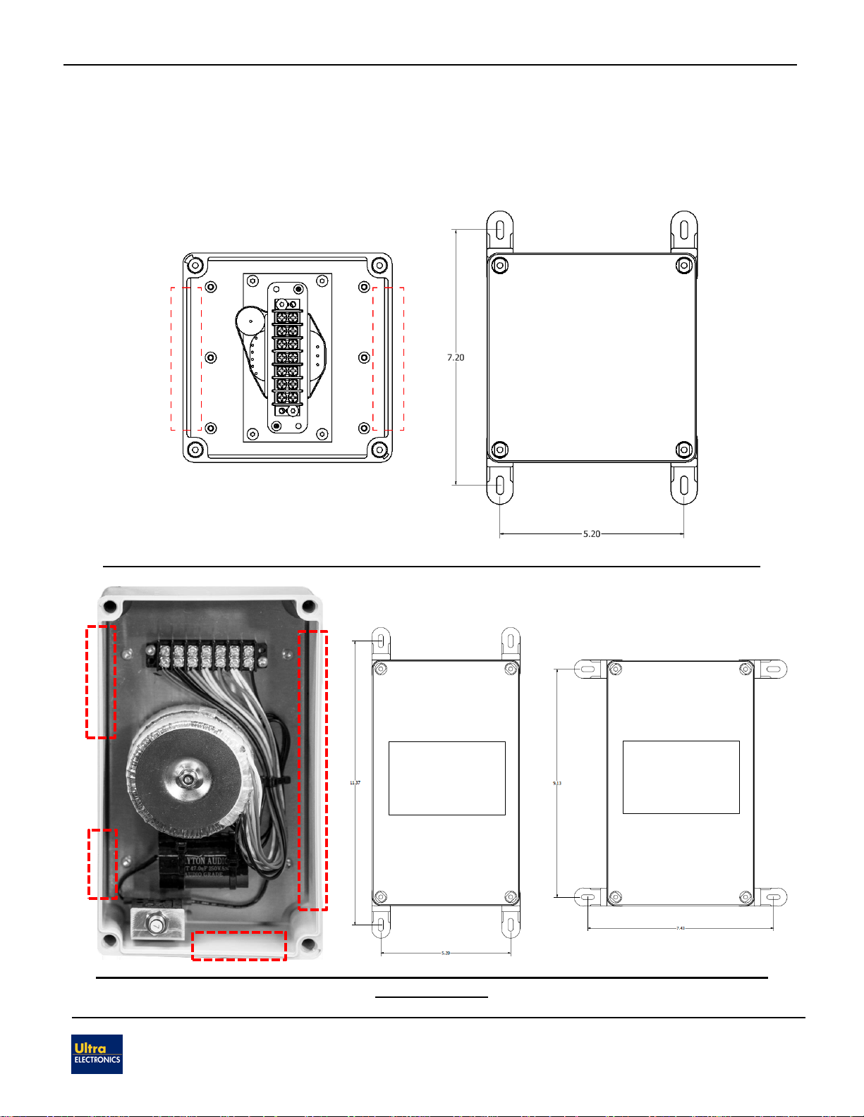
Figure 1. Wiring Diagram - 90243A-801, 90243-802, and 90243A-803
Figure 2. Wiring Diagram - 90243A-804
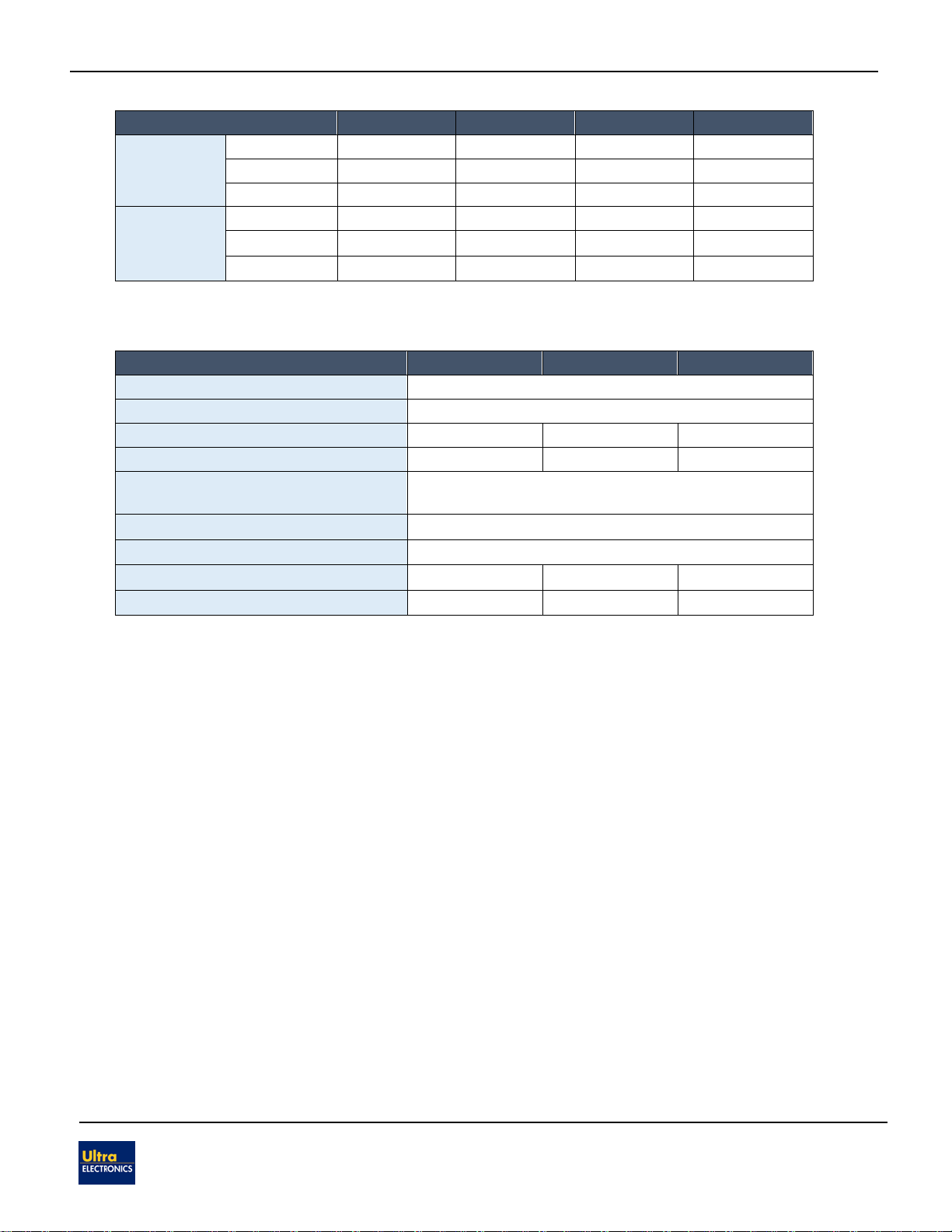
2.2. Distributed Audio System Overview
An optional 25V/70V/100V transformer allows the LineWave to be connected to 25V, 70V,
or 100V distributed audio networks. It has four field-selectable power taps on the provided
terminal block that allow the output SPL to be tuned to specific applications. The
25V/70V/100V transformer assembly also has an integrated DC blocking capacitor that
allows amplifiers to conduct DC circuit supervision. The taps can be selected by wiring
25/70/100V input lines to the appropriate terminal block contacts, as shown in the wiring
diagrams included in this section. Once the system is mounted, reference Section 3 for
tables detailing the power draw and output SPL of LineWave speakers when using the
available transformer tap settings.
Note: Section 1.2 lists the 25V/70V/100V transformers which are available for each model of
LineWave loudspeaker.
Note: Terminal Block is rated for 22-14AWG wire