Copyright © Ultra Electronics USSI Columbia City, IN 46725 USA
AHDi Operation and Maintenance Manual
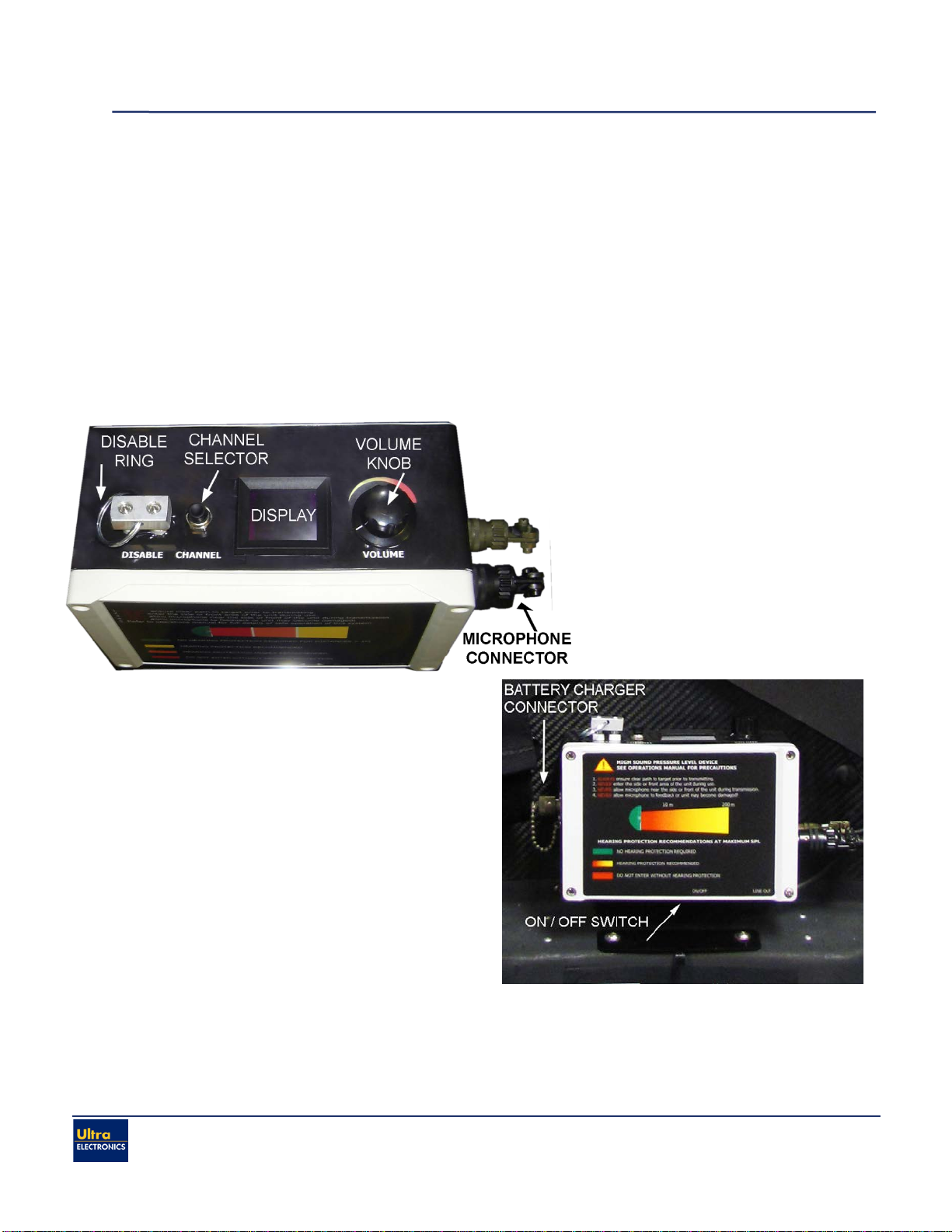
1.4. Selecting the Alert Tone
The AHDi alert tone is used to get attention, provide warnings,
etc. To broadcast the alert tone, press the CHANNEL selector
button on the control module until the display reads 1. Press the
TRIGGER button as shown in Figure 1.4-1. To increase the
volume of the message, turn the VOLUME knob clockwise. The
alert tone will broadcast as long as the TRIGGER button is
depressed.
1.5. Selecting a Pre-Recorded Message
To select a pre-recorded message, press the CHANNEL selector on the control module until the
display reads a number between 2-9. Each press of the CHANNEL button will index the display to the
next message in the rotation of messages.
Once your desired message is selected, hold down the TRIGGER button to broadcast. To increase the
broadcast volume, turn the VOLUME knob clockwise. The message will broadcast as long as the
TRIGGER button is depressed.
1.6. Disable Ring
The AHDi is configured with a DISABLE ring or kill
switch. See Figure 1.6-1. When the DISABLE ring is
pulled out from the control module, the disable switch
is activated to quickly terminate power to the AHDi
speaker thus immediately preventing all audio
messages & alert tones from being broadcast. As a
safety precaution, the DISABLE ring may be tethered
to the operator for use during crowd control scenarios.
When the DISABLE ring is pulled out from the control
module, the numeric display will show rotating bars to indicate the disengagement. To reactivate,
simply reinsert the DISABLE ring into the control module. The power will be restored to the
speakers and the unit will operate as normal.
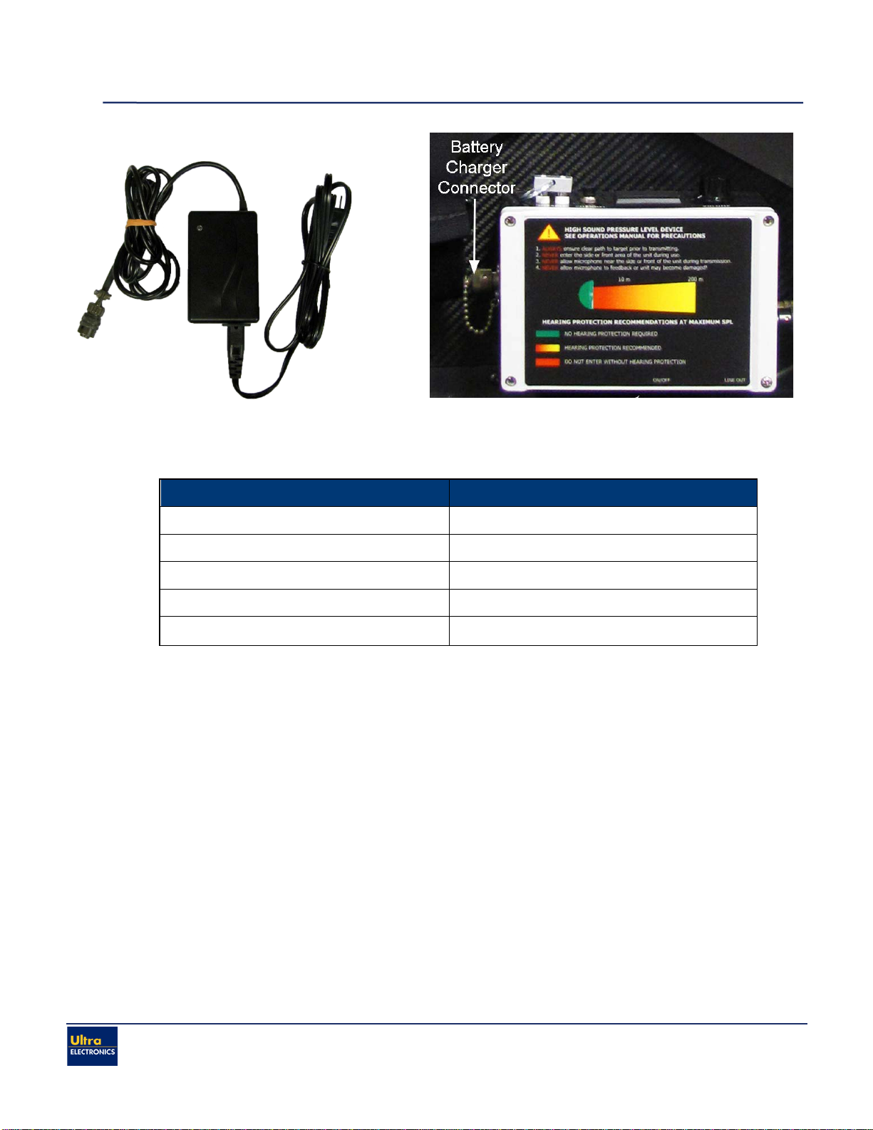
1.7. Charging the Battery
When the display shows a blinking “L”, the AHDi NiMH battery packs needs re-charging. Before
charging the AHDi, ensure that the POWER switch is in the OFF position. Using the battery
charger supplied with the AHDi, connect the Amphenol connector to the control module battery
connector shown in Figure 1.7-1. Connect the two-prong connector to a power outlet with a
voltage between 100 – 240 VAC. The AHDi battery pack will automatically begin charging.
The charger is equipped with an LED charging indicator. Figure 1.7-2 provides guidance on the
charging status of the AHDi battery pack.
Figure 1.6-1: Disable Ring
Figure 1.4-1: AHDi Trigger Button